Note: Descriptions are shown in the official language in which they were submitted.
1
SAMPLING PIPETTE HAVING AN ERGONOMIC CONTROL BUTTON
The present invention relates to the field of sampling pipettes, also referred
to as
laboratory pipettes or liquid transfer pipettes. They are intended for the
sampling and
dispensing of liquid in containers or similar.
The invention relates more specifically to manual, single-channel or multi-
channel
pipettes. In a known manner, manual pipettes are intended to be held in the
hand by an
operator during liquid sampling and dispensing operations, these operations
being carried
out by actuating the movement of a control button obtained by applying an
axial pressure
on said button. The axial pressure applied to the control button is
transmitted to a piston
of the pipette, via a control rod of the pipette. The piston is subject to
axial displacement
and induces a displacement of air resulting in the sampling and dispensing
operations. This
principle relates to so-called air displacement pipettes, wherein a sampling
cone is
intended to be removably mounted on the tip of the pipette. Nevertheless, the
invention
also applies to so-called positive displacement pipettes, intended to engage
with capillary-
piston type consumables, wherein the piston is envisaged to be directly in
contact with the
sample to be taken, before being ejected or reused. Positive displacement
pipettes
therefore have a different design to that of more conventional air
displacement pipettes,
wherein the piston is an integral part of the pipette.
Regardless of the design adopted, there is a constant need to improve the
ergonomics of these pipettes, in particular in order to facilitate the
movements of the
operator's thumb during liquid dispensing or intake operations, as well as
during draining.
Indeed, at the start of the downward travel of the control rod, the operator's
inclined
thumb only has a small contact area with the button, which obliges the
operator to develop
a significant force in order to generate the sought displacement. This may
give rise to
pipetting comfort problems, as well as the appearance of musculoskeletal
disorders (MSD).
In order to address this need (for example), and according to one possible
aspect of
the present invention, an object is to provide an assembly for a sampling
pipette including
a control rod at the end of which is arranged a control button for controlling
the movement
Date recue / Date received 2021 -1 1-29
la
of the control rod along a longitudinal axis thereof, the button having a
pressure surface
for receiving the thumb of an operator,
wherein the pressure surface of the control button is movable such as to be
able,
during operation, to assume multiple angles relative to the longitudinal axis
of the control
rod.
According to another aspect of the present invention, there is also provided a
sampling pipette including an assembly such as the one described and/or
illustrated in the
present patent specification.
Other possible aspect(s), object(s), embodiment(s), variant(s) and/or
advantage(s)
of the present invention, all being preferred and/or optional, are briefly
summarized
hereinbelow.
For example, and as previously discussed, in order to address the
aforementioned
need, the invention relates to an assembly for an ergonomic sampling pipette
including a
control rod at the end of which is arranged a control button for controlling
the movement
of the control rod along a longitudinal axis thereof, the button having a
pressure surface
for receiving the thumb of an operator. According to the
Date recue / Date received 2021 -1 1-29
CA 02962904 2017-03-28
S 57226 AP/P
2
invention, the pressure surface of the control button is movable such as to be
able, during
operation, to assume multiple angles relative to the longitudinal axis of the
control rod.
In other words, an additional degree of freedom is introduced at the control
button,
such that in operation, the angle of the pressure surface thereof adapts to
the changeable
angle of the distal phalanx of the thumb of the operator holding the pipette
in the hand.
By means of this additional degree of freedom, the position of the pressure
surface is thus
capable of changing to follow the natural rotational movement of the distal
phalanx of the
thumb, relative to the proximal phalanx, during the descent and ascent of the
control rod.
This results in superior pipetting comfort, with particularly superior strain
distribution on
the thumb joints, and a force of lower intensity to be developed to induce the
descent of
the control rod via the button. This is conveyed by a reduction in muscle
fatigue, as well as
a limitation of the risks of the onset of musculoskeletal disorders.
The invention has at least one of the following features, taken alone or in
combination.
The control button is pivotally mounted on the control rod, along a pivoting
axis
arranged in a plane orthogonal to the longitudinal axis of the control rod.
Alternatively, the
control button could be made of two parts, including a base mounted on the
control rod,
and a movable end part pivotally mounted on the base, and including said
pressure surface
intended to be contacted by the thumb.
The control button is pivotally mounted between two end positions, switching
from
one to the other of the two end positions being performed by pivoting by a
total range of
rotation between 10 and 450, and more preferentially between 15 and 25 .
The assembly includes means for returning the pressure surface to a rest
position,
which can equally be one or the other of the two end positions cited above.
The pressure surface has a convex shape so as to define a cradle for receiving
the
operator's thumb.
The convexity axis of the pressure surface of the control button is
substantially
orthogonal to a pivoting axis of the control button.
CA 02962904 2017-03-28
S 57226 AP/P
3
The invention also relates to a sampling pipette including such an assembly,
the
pipette being of the air displacement or positive displacement type, and of
the single-
channel or multi-channel type.
Further advantages and features of the invention will emerge in the non-
limiting
detailed description hereinafter.
The description will make reference to the appended drawing wherein;
- figure 1 represents a perspective view of an air displacement sampling
pipette,
according to a preferred embodiment of the present invention;
- figure 2 represents a more detailed side view of the control button of the
pipette
shown in the preceding figure;
- figure 3 represents a rear view of the control button shown in the preceding
figure;
- figure 4 represents a view schematically representing the two end
positions of the
control button;
- figure 5 represents the pipette held by the operator at the time of an
end of liquid
intake travel, the time at which the button adopts one of the two end
positions; and
- figure 6 represents the pipette held by the operator at the time of an end
of liquid
drainage travel, the time at which the button adopts the other of the two end
positions.
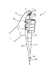
With reference first of all to figure 1, a manually actuated air displacement
sampling
pipette 1 is represented, according to a preferred embodiment of the present
invention.
Hereinafter in the description, the terms "top" and "bottom" are to be
considered with the
pipette held upright, in the pipetting position or close to this position.
In figure 1, the pipette 1 held by the hand 2 of an operator, who, using the
thumb 4,
actuates the pipette to induce the dispensing of a previously aspirated
liquid, is
represented.
More specifically, the pipette 1 includes a handle 6 acting as the upper body
of the
pipette, from which handle a pipetting control rod 10 emerges bearing at the
top end
thereof, in the pipetting position, a control button 12 wherein the top part
is intended to
be subjected to the pressure of the operator's thumb. More specifically, the
button has a
pressure surface 11 intended to receive the operator's thumb, this surface
generally facing
upwards.
CA 02962904 2017-03-28
S 57226 AP/P
4
By way of indication, it is noted that a display screen (not shown) can be
provided
on the handle 6. Similarly, means for setting the volume to be sampled are
also accessible
to the operator on this handle 6.
Below the handle 6, the pipette 1 includes a removable bottom part 14, which
ends
at the bottom with a cone-holder tip 16 receiving a consumable 18, also
referred to as a
sampling cone. In a known manner, after pipetting, the cone can be ejected
mechanically
by an ejector 20 wherein the actuation button 22 is situated for example
projecting on the
top of the handle, in the vicinity of the control button 12.
Figures 2 and 3 show in more detail the control button 12, pivotally mounted
at the
top end of the control rod 10. To carry out such pivoting, a piece 24 passes
through both
the rod 10 and the bottom part of the button 12. The piece 24 is oriented
along a pivoting
axis 26, orthogonal to the longitudinal axis 28 of the control rod, and
arranged in a plane
orthogonal to said axis 28. The latter also corresponds to the longitudinal
axis of the
pipette, as well as to the direction of displacement of the rod 10 during the
pipetting
operations.
It is noted that in a preferred embodiment of the invention, the pair
referenced 10
in figures 2 and 3 does not form the top end of the control rod, but
alternatively forms a
part of the button 12. Indeed, the control button could be made of two parts,
including a
base mounted on the control rod and corresponding to the element referenced 10
in
figures 2 and 3, and a movable end part pivotally mounted on the base, via the
piece 24.
The button 12 therefore has a convex pressure surface 11 so as to define a
cradle
for receiving the operator's thumb. This cradle assumes a cylindrical shape,
having two
raised edges 30 to prevent lateral sliding of the thumb. These two edges 30
are arranged
on either side of a convexity axis 11a of the surface 11, this axis 11a being
orthogonal to
the pivoting axis 26.
The radius of curvature R of the surface 11 is for example of the order of 20
mm.
Moreover, the spacing E between the pivoting axis 26, and the bottom of the
cradle
defined by the surface 11, is of the order of 3 to 5 cm, and preferentially
approximately
4 cm. Furthermore, the distance D1 from a transversal plane P1 of the button
12
incorporating the pivoting axis 26, to a first end 36a of said button 12, is
between 10 and
=
CA 02962904 2017-03-28
,
S 57226 AP/P
14 cm, and preferably of the order of 12 cm. Said first end 36a corresponds to
an end along
the convexity axis 11a, and more specifically to that intended to engage with
the anterior
part of the distal phalanx of the operator's thumb. In addition, the distance
D2 from the
transversal plane P1 to a second end 36b of the button 12 is between 13 and 17
cm, and
5 preferably of the order of 15 cm. Said second end 36b is opposite the
first along the
convexity axis 11a, and therefore corresponds to that intended to engage with
the
posterior part of the distal phalanx of the thumb.
The assembly 3 according to the invention, including the button 12 and the rod
10,
is also equipped with means 40 for returning the button to a rest position,
shown in figures
2 and 3. This consists preferably of a compression spring 40 inserted between
a
protuberance 42 of the button, and the top part of the control rod 10.
In this regard, it is noted that in the embodiment described above, wherein
the
control button is made of two parts with the base thereof corresponding to the
element
referenced 10 in figures 2 and 3, the spring 40 is then bearing on said base.
The base
advantageously offers a larger surface area than that of the rod to receive
the spring 40.
The base assumes for example a tubular shape mounted about the top end of the
control
rod, the piece 24 then passing through the base and the top part of the
button, as shown
in figure 1.
The spring 40 therefore returns the button to a rest position which
corresponds to
a position wherein it has a maximum angle relative to a plane orthogonal to
the longitudinal
axis 28. This consists of one of the two end positions of a pivoting movement
of the
button 12 along the axis 26.
By means of this pivoting movement, the button 12 can thus assume a plurality
of
angles during the pipetting operations, by adapting to the changeable position
of the distal
phalanx of the operator's thumb.
In figure 4, the button 12 has been represented in the two end positions of
the
permitted pivoting movement thereof about the axis 26. The most inclined
position
represented with a dotted line, corresponding to that previously shown in
figure 2, is such
that the angle Al between the horizontal 50 and the convexity axis ha is of
the order of
350. In this regard, it is noted that in figure 4, the line 50 represents both
the horizontal and
CA 02962904 2017-03-28
S 57226 AP/P
6
a plane orthogonal to the axis 28. An angle Al greater than 35 is possible,
but liable to
induce parasitic radial loads on the rod 10. This position is adopted when the
rod is at the
top stop, i.e. at the end of the sampling operation, and before the start of
the dispensing
operation. Indeed, in this design shown in figure 5, the angle between the
distal phalanx 4a
and the proximal phalanx 4b is small. The distal phalanx 4a is therefore found
to be
significantly inclined with respect to the horizontal, but the pivoting
pressure surface 11
makes it possible to adapt perfectly to this particular orientation of the
phalanx 4a, while
being in turn inclined. In this position, the cradle of the button thus
receives the phalanx 4a
wherein the longitudinal axis is advantageously parallel to the convexity axis
11a.
This shape complementarity is retained during all the pipetting operations, by
means of the pivoting nature of the button 12 which can follow the rotary
movement of
the distal phalanx 4a, relative to the proximal phalanx 4b.
In figure 4, the button 12 has also been represented in the other of the two
end
positions of the pivoting movement thereof about the axis 26. This consists of
the least
inclined position, approaching the fixed position encountered in conventional
pipettes. This
second end position is that wherein the angle A2 between the horizontal 50,
and the
convexity axis 11a, is of the order of 15 . A lesser angle is possible, but
less ergonomic due
to the significant angle required between the distal and proximal phalanxes
4a, 4b. This
position is adopted when the rod is at the bottom stop, i.e. at the end of the
dispensing
operation or at the end of the draining operation. Indeed, in this design
shown in figure 6,
the angle between the distal phalanx 4a and the proximal phalanx 4b is
relatively large. The
distal phalanx 4a is thus found to be slightly inclined with respect to the
horizontal, but
always perfectly received in the cradle of the button oriented accordingly.
The total angle of rotation A3 of the button 12 is thus of the order of 20 ,
and more
generally between 15 and 25 . The switch from the first end position to the
second end
position is performed by countering the return force developed by the spring
40, this force
being preferentially very low so as not to affect the ergonomics of the
pipette. Mechanical
stop systems make it possible to limit the pivoting movement of the button 12
between
the two end positions cited above. Moreover, it is noted that according to the
size of the
operator's thumb, the pipetting operations can be carried out without reaching
one and/or
=
CA 02962904 2017-03-28
S 57226 AP/P
7
the other of the two end positions, but always observing an adaptation of the
angle of the
button 12 according to the changeable position of the distal phalanx 4a of the
operator's
thumb.
Obviously, various modifications can be made by those skilled in the art to
the
invention described above, merely by way of non-limiting examples.