Note: Descriptions are shown in the official language in which they were submitted.
=
APPARATUS AND METHOD FOR PATTERN CREATION
BACKGROUND OF THE INVENTION
[0001]
Technical Field
[0002] The present invention generally relates to a flexible system for
creating patterns
of pillow bags. For example, the system relates to an apparatus and method for
creating pillow
bag patterns of various counts, product types, products sizes, product
arrangements, and product
orientations. In some embodiments, the apparatus and method for creating
pillow bag patterns
packs these patterns into various containers, for example, caddies, cases,
trades, sacks, universal
surfaces.
[0003] Additionally, the present invention generally relates to measuring a
thickness of
a moving pillow bag and using the measurement to pick and place the pillow
bag. For example,
the invention relates to an apparatus and method for measuring a thickness of
a moving pillow
bag and using the measurement to pick and place the pillow bag.
[0004] The present invention also generally relates to determining the
position and
orientation of a pillow bag and using the position and orientation of the
pillow bag to pick and
place the pillow bag.
[0005] In some embodiments, the pillow bag is easily damaged or difficult to
accurately and precisely pick and place. In one embodiment a system for moving
the pillow bag
comprises a conveyor belt and a robot that is positioned to pick the bag from
the conveyor belt
and place the pillow bag in an array. For example, in one embodiment the
position, orientation
and measured thickness of the pillow bag is used to position the robot so that
damage to the
pillow bag and other pillow bags is avoided while a robot picks and places the
pillow bag to
form a desired pattern.
CA 2963064 2017-07-05
CA 02963064 2017-03-28
WO 2016/054561 PCT/US2015/053810
[0006] In some embodiments, the invention generally relates to a compound
angled
universal surface for receiving placed pillow bags and maintaining the pillow
bags in a desired
position and orientation while a pattern is formed, while the pillow bags are
transported, while
the pillow bags are transferred to an ultimate package or some combination
thereof. For
example, in one embodiment the surface is universal in the sense that the
walls of the universal
surface do not need to be adjusted to support pillow bags in a desired
position and orientation
(e.g. an upright position). For example, a top surface of the universal
surface, upon which a
pattern is placed, is at a compound angle so that one corner is lower than all
the other corners.
One result of the compound angle is that gravity tends to pull bags towards
the lowest corner.
Accordingly, in some embodiments the walls of the universal surface do not
need to be adjusted
to support pillow bags in upright position. Although some embodiments of the
universal surface
comprise a compound angle and a lowest corner, in other embodiments, the
universal surface
comprises a single angle and a lowest edge. For example, in embodiments with a
lowest edge
gravity tends to pull bags toward the lowest edge. Accordingly, the pillow
bags tend to be held
in place by gravity without, for example, needing to be constrained on all
sides by walls.
[0007] The present invention also generally relates to a method and apparatus
for a
universal surface that is decoupled from a conveyor for the universal surface.
For example, in
some embodiments this decoupling allows the universal surface to travel along
various paths to
the pattern creation cells where the universal surface is filled with pillow
bags by a robot or
travel various paths to pattern transfer stations where completed patterns can
be transferred to
packaging.
[0008] The present invention also generally relates to an apparatus and method
for
transferring products from a universal surface to an ultimate package (e.g.,
box, case, sack, tray,
carton, etc.). In one embodiment, a robot with an end effector transfers
product from the
universal surface to the ultimate package and the end effector comprises a
vacuum nozzle and a
finger wall which, for example, along with other crowder walls, can act like a
shoehorn. In some
embodiments, the universal surface comprises a mating or matching finger wall.
In some
embodiments, the end effector finger wall passes through the corresponding
finger wall of the
universal surface when the end effector picks product for placement in an
ultimate package (e.g.,
cardboard box). In some embodiments, product is transferred to the universal
surface from an
alternate package by tipping the universal surface upside down.
[0009] The present invention also generally relates to an apparatus or method
for a
quality control system for conveying pillow bags, picking pillow bags, placing
pillow bags,
transferring pillow bags, or some combination thereof. In one embodiment, a
pillow bag is
rejected if it fails to meet at least one condition. In one embodiment, an
input device can be
-2-
CA 02963064 2017-03-28
WO 2016/054561 PCT/US2015/053810
stopped if any robot has been unable to complete its task of picking and
placing the pillow bag
before the pillow bag or a universal surface is conveyed outside the robot's
area of influence.
Background
[0010] In many manufacturing, handling and transportation processes, pillow
bags (e.g.
bags of potato chips or cookies) need to be placed in specific patterns for
placement in a sack,
tray, box, wrap or other packaging. In many cases, the pillow bags have
variable positions,
orientations, or dimensions, such as thickness. For example, the position of a
pillow bag on a
conveyor belt constantly changes as the conveyor belt moves. In addition, the
position of the
pillow with respect to the conveyor belt can change. For example, the pillow
bag may be closer
to one edge of a conveyor belt than another. Another potential variable is the
orientation of the
pillow bag on the conveyor belt. The pillow bag can be tilted in one direction
or another, be
facing up, be facing down, or be rotated. Furthermore, the pillow bag can have
variable bag
dimensions in at least four situations. First, given a batch of bags from a
single product
manufacturing run, there are often variations in the size of the product.
Second, bags in batches
of a product run on different days can vary in size. Third, bag dimensions can
vary for bags of
different kinds of product or bags of product intentionally made in different
sizes. Fourth, it
might be desirable for bags with intentionally different sizes to be packaged
together.
[0011] If pillow bags are placed as close to each other as possible to
conserve space
and reduce costs for packaging or storage, the placement of one pillow bag
often depends on the
placement of previous pillow bags. For example, after a first pillow bag is
placed face-down in a
package next to a wall, the second pillow bag can only be accurately placed
next to the first
pillow bag if the position of the first pillow bag is known. If the width
and/or length of the first
pillow bag are known, it can be used to place the second pillow bag as close
as possible to a wall
of the package while still leaving room for the first pillow bag. Such an
arrangement can be
desirable to save space.
[0012] In other applications, it can be desirable to form a particular pattern
with pillow
bags with varying positions, orientations, and dimensions. For example, these
patterns can form
an attractive or useful arrangement for displaying the pillow bags to
consumers. However, the
process of determining the position, orientation, and dimensions of pillow
bags and then
accurately and precisely placing them in a high quality pattern can be
challenging. For example,
the pillow bags are often filled with air and can change shape or incur damage
upon contact with
a measuring device or a pick and place robot. Furthermore, the pillow bags are
often moving on
a conveyor belt and this can further complicate the task of measuring, picking
and placing the
bags. Nonetheless, being able to determine the position, orientation, and
dimensions of a
moving, non-rigid pillow bag can be critical for some applications.
-3-
CA 02963064 2017-03-28
WO 2016/054561 PCT/US2015/053810
[0013] To understand why determining the position, orientation, and thickness
of a
pillow bag is important, it is useful to review a traditional process for
putting pillow bags in a
box as described with reference to Figure 2A. In a first step 200, a batch of
bags is produced
with an assumed thickness. Second, in a picking step 202, a robot picks a bag
using the assumed
thickness from step 200. Third, in a placing step 204, after the robot picks
the bag, it places the
bag flat in a box. In placing the bag, the robot again uses the assumed
thickness. For example,
the assumed thickness is used to estimate how far the robot needs to stay from
the box while
placing the bag. If the robot gets too close to the box, the bag can be popped
between the robot
and the box. Fourth, in a repeating step 206, the steps of picking 202 and
placing 204 are
repeated until the box is full of bags.
[0014] As shown in Figure 2A, traditional manufacturing, handling, and
transportation
processes have used assumptions regarding a pillow bag's thickness to pick and
place the bag in
a box. Thus, while the thickness of potato chip bags can vary due to the
amount of air in the
bags, in a traditional manufacturing and handling process, all the bags are
assumed to have the
same thickness for the purposes of placing the bags in a pattern. Accordingly,
a pick and place
robot is positioned based on the assumption that each bag has a given
thickness. If the thickness
of a particular bag varies significantly from the assumed thickness, it can
result in damaged
product or poor pattern creation. For example, if a bag is thicker than
expected, the robot can get
too close and pop the bag. Alternatively, if a bag is thinner than expected,
the robot can remain
too far away and miss the bag altogether. In some cases, when a bag has
dimensions that vary
from assumed dimensions, a robot can pick the bag insecurely. Then, as the
robot moves with
the bag, forces acting on the bag cause the robot to lose its hold or suction
on the bag and hence
drop the bag.
[0015] Ultimately, imprecision and inaccuracy related to pillow bag position,
orientation, or thickness can result in misplaced and damaged bags, and
introduce inefficiencies
into the bag manufacturing, handling and transportation process. For example,
because
assumptions are used and actual product thicknesses can vary, tolerance must
be built into a
manufacturing, handling, and transportation system. This tolerance can take
the form of leaving
extra space on a conveyor belt or between bags in a package. However, this
extra space can be
wasted on the majority of bags which do not actually require extra space.
Likewise, packages
and equipment must be larger, resulting, for example, in greater expense,
greater use of energy,
and greater use of natural resources.
[0016] Down time to address dropped, damaged, or misplaced pillow bags is
another
inefficiency that can occur in a product manufacturing, handling and
transportation process as a
result of assumptions or inaccurate information regarding the dimensions of a
product.
-4-
CA 02963064 2017-03-28
WO 2016/054561 PCT/US2015/053810
[0017] Another problem with existing pattern creation systems is their
inability to
efficiently and effectively form patterns, especially more complicated
patterns.
[0018] What is needed is a new and innovative system capable of forming more
complicated patterns in an effective and efficient way while limiting the
amount of bags lost due
to damage as a result of incorrect assumptions regarding bag dimensions.
[0019] Additionally, there has been no reliable method of determining the
position,
orientation, and dimensions of a moving pillow bag and using that information
to pick and place
the pillow bag to form a high quality pattern, while simultaneously avoiding
damage to the
pillow bag. Some traditional methods for picking and placing a pillow bag make
assumptions as
to the pillow bag's dimensions, but result in damage to the product or poor
pattern creation or
have a negative impact on production rate if the actual dimensions vary
significantly from
assumptions. Accordingly, a system capable of measuring the dimensions of a
moving, non-
rigid pillow bag is desirable for the additional accuracy, precision,
reliability, efficiency and
cost-effectiveness it can provide. Such a system is also desirable because it
could increase
quality by reducing waste. For example, the system could avoid loss or damage
to bags that can
occur when a robot picks from an inaccurate height.
[0020] What is needed is a new and innovative system capable of determining
the
position, orientation, and dimensions of a moving pillow bag and using that
information to pick
and place the pillow bag to form a high quality pattern, while simultaneously
avoiding damage to
the pillow bag. For example, a need exists for a system that measures the
thickness of a pillow
bag on a running conveyor and feeds this thickness measurement to a pick and
place system.
Additionally a need exists for the pick and place system to make a dynamic
pick and dynamic
place using the measurement to adjust both the pick and place locations for
the pillow bag.
Accordingly, poor quality patterns, inefficiency, damaged product, dropped
product, and wasted
product can be avoided while the accuracy, precision, reliability, efficiency,
and cost-
effectiveness of the pick and place system is simultaneously increased. In
some embodiments,
resources can be conserved and the environmental friendliness of the process
can be increased.
[0021] Another problem that exists with conventional processes for picking and
placing
pillow bags is that if, for example, pillow bags were placed in a pattern on a
tray, they would
tend to move around. It would be advantageous to have an apparatus and method
for
maintaining the position and orientation of pillow bags once they have been
placed in a pattern.
It would also be advantageous if the apparatus (e.g., a tray) and method did
not require
adjustment for different shapes or sizes of pillow bag patterns. For example,
it would be
beneficial if the walls of the apparatus did not need to be positioned next to
the pillow bags to
maintain the pillow bags in a particular position or in an up-right
orientation. It would also be
-5-
CA 02963064 2017-03-28
WO 2016/054561 PCT/US2015/053810
advantageous if the apparatus and method could prevent the pillow bags from
sliding or falling
over. It would be further advantageous if the apparatus and method provided
for uncoupling the
apparatus (e.g. tray) from a conveyor so that the apparatus had freedom to
travel along various
paths, rather than a single path determined by a single conveyor.
[0022] Problems would also exist with respect to conventional methods for
transferring
objects if they were applied to pillow bags, for example, to transfer a pillow
bag from a tray to
final package. In some cases, transferring patterns would be slow or
inefficient, for example, if
the patterns were transferred manually or because a robot performing the
motions required for a
transfer can only move so quickly. In other cases, transferring patterns could
result in disruption
to the pattern or damage to pillow bags. It would be beneficial to have an
apparatus and method
for more efficiently and effectively transferring a pillow bag pattern from
one surface to another
surface, for example, from a tray to a package. It would also be desirable if
the method and
apparatus used components that reduced the amount of motion required to
perform a pattern
transfer and thereby increased the speed and efficiency of the transfer. For
example, it would be
advantageous, if the method and apparatus used components that were slotted so
that the
components could pass through each other when a pattern was transferred
instead of having to
move around each other. It would also be advantageous if the method and
apparatus were
compatible with transferring a pillow bag pattern from a surface with a
compound angle. For
example, for a process in which a pattern of pillow bags are pushed from a
first surface to a
second surface, if the first surface is slanted, but the second surface is
flat, transferring pillow
bags from the first surface to the second surface can be complicated and
result in unacceptable
disruptions to the pattern as it is transferred. It would also be advantageous
if the method and
apparatus were compatible with transferring a pillow bag pattern from a
surface with a high
coefficient of friction, which, for example, can help to keep the pillow bags
from sliding. It
would also be advantageous if such a method and apparatus could transfer the
pattern using
suction to lift the pillow bags off the high-friction surface rather than
trying to push or slide the
pillow bags off the surface. It would also be advantageous to be able to
transfer pillow bags
from the surface by flipping the surface over and using gravity, centripetal
force, supports, or
some combination thereof to prevent a pillow bag pattern from being disturbed
to an
unacceptable degree.
[0023] Another problem that exists for picking and placing pillow bags is that
pillow
bags that don't meet desired quality criteria can be included in a pattern or
a pattern itself may
not meet certain quality criteria. For example, a bag may have a smudged or
off-center label, or
a pattern may be incomplete because the tray bearing the pattern moved past a
robot before the
robot had time to place its pillow bag on the tray. As another example, some
quality control
-6-
CA 02963064 2017-03-28
WO 2016/054561 PCT/US2015/053810
systems that use weight to verify whether a specified quantity of pillow bags
is present in a
pattern do not work well when the pattern can comprise various types of
products with various
weights. Accordingly, it would be advantageous to have an apparatus and method
for verifying
the quality of pillow bags and patterns, including, for example, patterns that
comprise products
of variable number and type. It would also be desirable if such a method and
apparatus could
reject pillow bags if they fail to meet quality control criteria. It would
also be advantageous if
such a method and apparatus could provide for stopping a conveyor if a robot
has not been able
to pick and place or transfer a pillow bag.
[0024] It would also be beneficial if a system capable of determining the
position,
orientation and dimensions of a moving pillow bag could transmit information
about the
position, orientation and dimensions of the pillow bag to other systems. For
example, it would
be useful if one pattern creation cell with information about the position and
dimensions of
pillow bags could transmit this information to other pattern creation cells.
As a result, a pattern
created by one pattern creation cell could be added to or modified by another
pattern creation
cell. For example, one pattern creation cell could place bags in a first row
on a tray, while a
second pattern creation cell could place bags in a second row that is adjacent
to the first row.
Pattern creation cells could also be used together to create more complicated
patterns. This
would provide flexibility with respect to designing patterns and the
efficiency and cost-savings
with respect to reducing or eliminating misplaced and damaged product.
It would also be beneficial if a method and apparatus for picking and placing
pillow bags were
able to send information to a downstream device, for example a pattern
transfer device. It would
also be advantageous if the pattern transfer device could be used to transfer
a pattern of pillow
bags from one surface to another, and the pattern could comprise at least one
column of bags. In
transferring such a pattern, it would also be desirable if information on the
length of the at least
one column of bags could be used to improve pattern transfer performance.
-7-
CA 02963064 2017-03-28
WO 2016/054561 PCT/US2015/053810
SUMMARY OF THE INVENTION
[0025] The present invention generally provides for an apparatus and method
for
measuring a thickness of a moving pillow bag and using the measurement to pick
and place the
pillow bag. The pillow bag can be a non-rigid product, for example, a bag of
chips, and the
pillow bag can comprise variable dimensions and exhibit various conditions and
orientations.
For example, the amount of air in the bag can vary, and this in turn, can
change the thickness of
the bag.
[0026] A robot can be used to pick and place the pillow bag, and the robot can
be
positioned using the measured thickness. In some embodiments, the robot is
capable of picking
and placing pillow bags with the use of an end effector. In some embodiments,
the robot is a
delta robot. In some embodiments, the robot forms a component of a pattern
creation cell. For
example, the pattern creation cell can be used to measure the thickness,
position, and orientation
of a moving pillow bag and pick and place the bag in an array according to a
desired pattern.
[0027] In one embodiment, the pattern creation cell can also transmit
information
regarding the thickness, position, and orientation of pillow bags in an array
of pillow bags. For
example, this information can be transmitted from one pattern creation cell to
another or to a
programmable automation controller ("PAC"), programmable logic controller,
("PLC") or
computer (e.g., personal computer ("PC")), which can then transmit the
information to other
pattern creation cells. The pattern creation cells can also be used together
or in combination to
form patterns that are more complex or complicated than the patterns created
by individual
pattern creation cells.
[0028] In a first aspect, the invention provides an apparatus for use in
picking and
placing a non-rigid object, said apparatus comprising a first input device and
a feed forward unit,
wherein the first input device conveys a non-rigid object into contact with
the feed forward unit,
which contact causes a displacement of the feed forward unit, wherein the
displacement is used
to measure directly or indirectly a measured dimension of the non-rigid
object, and wherein the
measured dimension is transmitted via a line of communication and used to pick
and place the
non-rigid object. For example, in one embodiment the invention comprises an
apparatus that can
measure a thickness of a moving pillow bag and use it to pick and place the
pillow bag.
[0029] In a second aspect, the invention provides a method for measuring a
dimension
of a non-rigid object and using the dimension in picking and placing the
object, said method
comprising the steps: measuring a dimension of a moving non-rigid object to
provide a measured
dimension; using the measured dimension to pick the non-rigid object; and
using the measured
dimension to place the non-rigid object. In one embodiment, the measuring step
comprises:
using a first input device to convey the non-rigid object into contact with a
feed forward unit,
-8-
CA 02963064 2017-03-28
WO 2016/054561 PCT/US2015/053810
wherein the contact causes a change in position of the feed forward unit to
accommodate the
measured dimension of the non-rigid object; and using a distance sensor to
detect directly or
indirectly the change in position or displacement of the feed forward unit. In
another
embodiment, the invention provides a method for measuring a thickness of a
moving pillow bag,
using the measurement of the thickness to pick the pillow bag, and using the
measurement of the
thickness to place the pillow bag in an array of pillow bags according to a
desired pattern.
[0030] In a third aspect, the invention provides an apparatus for use in
picking and
placing a non-rigid object, said apparatus comprising a first input device and
a feed forward unit,
wherein the first input device conveys a non-rigid object into contact with
the feed forward unit,
which contact conditions the object to form a conditioned object. A distance
sensor is positioned
over a gap in the feed forward unit to measure a distance to a surface of the
conditioned object
and the distance to the surface of the object measures a measured dimension of
the conditioned
object. The measured dimension is transmitted via at least one line of
communication and used
to pick and place the non-rigid object. For example, in one embodiment the
invention comprises
an apparatus that can measure a thickness of a moving pillow bag and use it to
pick and place the
pillow bag.
[0031] In a fourth aspect, the invention provides a method for measuring a
dimension
of a non-rigid object and using the dimension in picking and placing the
object, said method
comprising the steps: measuring a dimension of a moving non-rigid object to
provide a measured
dimension; using the measured dimension to pick the object; and using the
measured dimension
to place the object in an array of objects. In one embodiment, the measuring
step comprises:
using a first input device to convey the object into contact with a feed
forward unit, wherein the
contact conditions the object to form a conditioned object; and using a
distance sensor to detect
directly or indirectly a distance across two opposite surface of the
conditioned object. In another
embodiment, the invention provides a method for measuring a thickness of a
moving pillow bag,
using the measurement of the thickness to pick the pillow bag, and using the
measurement of the
thickness to place the pillow bag in an array of pillow bags according to a
desired pattern.
[0032] In a fifth aspect, the invention provides an apparatus for transferring
a pattern
from a universal surface to an ultimate package, said apparatus comprising: an
end effector for a
pattern transfer robot; wherein the universal surface comprises a finger wall,
said finger wall
comprising a series of finger wall slats spaced apart a distance to form
openings between the
finger wall slats, wherein the end effector comprises a crowder plate, said
crowder plate
comprising a series of crowder plate slats spaced apart a distance to form
openings between the
crowder plate slats, and wherein a portion of the crowder plate slats are
sized to pass between a
portion of mating finger wall slats.
-9-
CA 02963064 2017-03-28
WO 2016/054561 PCT/US2015/053810
[0033] In a sixth aspect, the invention provides a method for transferring a
pattern of
non-rigid objects from a universal surface to an ultimate package, said method
comprising the
steps of: providing a pattern on a universal surface; conveying the pattern to
a transfer station;
picking the pattern with an end effector at the transfer station; and placing
the pattern into an
ultimate package, said ultimate package comprising at least one layer of non-
rigid objects to
form at least one universal element.
[0034] In a seventh aspect, the invention provides an apparatus for
maintaining a
pattern of non-rigid objects in a desired position and orientation, said
apparatus comprising: a
first surface; a second surface; a third surface; a lowest corner; and a
bottom, wherein the first
surface, second surface, and third surface are mutually orthogonal and meet at
a point to form the
lowest corner, wherein the second and third surfaces are supported by,
attached to and extend at
least somewhat vertically from the apparatus, wherein the first surface is
oriented at a compound
angle to a plane running through the bottom and thereby provides the lowest
corner.
[0035] In an eighth aspect, the invention provides a method for loading non-
rigid
objects on a compound-angled universal surface to form a pattern, said method
comprising the
steps of: picking non-rigid objects; and placing the objects in a first
pattern on a compound-
angled universal surface so that the objects are supported by three mutually
orthogonal surfaces
of the universal surface.
[0036] In a ninth aspect, the invention provides a method for loading a
pattern of non-
rigid objects on a universal surface that is decoupled from a universal
surface conveyor, said
method comprising the steps: supplying the universal surface to a pattern
creation line on a first
universal surface conveyor, wherein the universal surface is decoupled from
the first universal
surface conveyor; conveying the universal surface to a first decision point
where the universal
surface can be directed to at least a second universal surface conveyor;
conveying the universal
surface to at least one pattern creation cell to form a finished pattern; and
conveying the
universal surface with the finished pattern to at least one pattern transfer
station for transferring
the finished pattern to an ultimate package; wherein the pattern creation line
comprises the first
decision point, the at least one pattern creation cell, the at least one
pattern transfer station, the
first universal surface conveyor, and the at least a second universal surface
conveyor.
[0037] In a tenth aspect, the invention provides a method for using multiple
lanes to
load a pattern of non-rigid objects on a universal surface that is decoupled
from a universal
surface conveyor, said method comprising the steps: loading a pattern of
objects onto the
universal surface; conveying a universal surface on a work in-progress lane
comprising a first
universal surface conveyor, wherein the universal surface is decoupled from
the first universal
surface conveyor; conveying the universal surface to an express lane
comprising a second
-10-
CA 02963064 2017-03-28
WO 2016/054561 PCT/US2015/053810
universal surface conveyor after the universal surface has been loaded with a
finished pattern,
wherein the universal surface is decoupled from the second universal surface
conveyor, and
wherein, as compared to the work-in-progress lane, the express lane provides a
more direct route
to a destination of the universal surface.
[0038] In an eleventh aspect, the invention provides an apparatus for
maintaining a
pattern of non-rigid objects in a desired position and orientation, said
apparatus comprising: a
first surface; a second surface; a third surface; a lowest edge; and a bottom,
wherein the first
surface, second surface, and third surface are mutually orthogonal and meet at
a point to form a
corner, wherein the first surface and second surface meet to form a lowest
edge, wherein the
second and third surfaces are supported by, attached to and extend at least
somewhat vertically
from the apparatus, wherein the first surface is oriented at an angle to a
plane running through
the bottom and thereby provides the lowest edge.
[0039] In a twelfth aspect, the invention provides a method for loading non-
rigid
objects on a universal surface to form a pattern, said method comprising the
steps: picking non-
rigid objects; and placing the objects in a first pattern on an angled
universal surface so that the
objects are supported by at least two of three mutually orthogonal surfaces of
the universal
surface.
[0040] The inventors have developed a new and innovative system capable of
forming
complicated patterns of non-rigid objects in an effective and efficient way
while limiting the
amount of bags lost due to damage as a result of incorrect assumptions
regarding bag
dimensions.
[0041] The inventors have also developed a new and innovative system capable
of
determining the position, orientation, and dimensions of a moving pillow bag
and using that
information to pick and place the pillow bag to form a high quality pattern,
while simultaneously
avoiding damage to the pillow bag and negative impacts on production rate. For
example, in one
embodiment, the invention is an apparatus that determines the position,
orientation, and
thickness of a non-rigid product (for example, bags) on a running conveyor and
can feed this
thickness measurement to a pick and place system. In an additional embodiment,
the pick and
place system makes a dynamic pick and dynamic place using the position,
orientation, and
thickness of a pillow bag to adjust both the pick and place locations for the
pillow bag.
Accordingly, in one embodiment the system avoids loss or damage to bags that
can occur when a
robot picks from an inaccurate height. In another embodiment, poor quality
patterns,
inefficiency, damaged product, wasted product, and negative impacts on
production rate can be
avoided while the accuracy, precision, reliability and efficiency of the pick
and place system is
simultaneously increased.
-11-
CA 02963064 2017-03-28
WO 2016/054561 PCT/US2015/053810
[0042] The system is also desirable because it increases quality by reducing
waste in
the form of lost or damaged bags that could have occurred as a result of
robots picking from an
inaccurate position (e.g. height) or orientation. Resources, for example,
natural resources or
energy, are conserved and the environmental friendliness of the process is
increased. The system
creates tighter patterns of pillow bags than a traditional manufacturing,
handling, or
transportation system. Further, the downtime of the system is reduced relative
to a traditional
system.
[0043] In one embodiment, the invention is an apparatus and method for
maintaining
the position and orientation of pillow bags once they have been placed in a
pattern. In one
embodiment, the apparatus and method do not require adjustment for different
shapes or sizes of
pillow bag patterns because, for example the apparatus comprises a compound
angled universal
surface. In one such apparatus and method, the walls of the apparatus do not
need to be
positioned next to the pillow bags to maintain the pillow bags in a particular
position or in an up-
right orientation. Another advantage of one such apparatus and method is that
it prevents the
pillow bags from sliding or falling over. In addition, one such apparatus and
method provides for
uncoupling the apparatus (e.g. a tray) from a conveyor so that the apparatus
had freedom to
travel along various paths, rather than a single path determined by a single
conveyor.
[0044] In one embodiment, the invention mitigates problems that exist with
respect to
conventional methods for transferring pillow bags, for example, from a tray to
final package. In
one embodiment, such an apparatus and method more efficiently and effectively
transfers a
pillow bag pattern from one surface to another surface, for example, from a
tray to a package.
Additionally, one such apparatus and method use components that reduce the
amount of motion
required to perform a pattern transfer and thereby increase the speed and
efficiency of the
transfer. For example, the method and apparatus use components that are
slotted so that the
components can pass through each other when a pattern is transferred instead
of having to move
around each other. Another such method and apparatus is compatible with
transferring a pillow
bag pattern from a surface with a compound angle and can also be used to
transfer a pillow bag
pattern from a surface with a high coefficient of friction, because, for
example, the apparatus and
method uses suction to lift the pillow bags off the high-friction, compound
angled surface rather
than trying to push or slide the pillow bags off the surface. Another such
apparatus and method
transfer's pillow bags from a surface by flipping the surface over and using
gravity, centripetal
force, supports, or some combination thereof to prevent a pillow bag pattern
from being
disturbed to an unacceptable degree.
[0045] In another embodiment, the invention is an apparatus and method for
verifying
the quality of pillow bags and patterns, including, for example, patterns that
comprise products
-12-
CA 02963064 2017-03-28
WO 2016/054561 PCT/US2015/053810
of variable number and type. One such a method and apparatus rejects pillow
bags if they fail to
meet quality control criteria. One such a method and apparatus also provides
for stopping a
conveyor if a robot has not been able to pick and place or transfer a pillow
bag.
[0046] In another embodiment, the invention is a system that determines the
position,
orientation, and dimensions of a moving pillow bag and transmits information
about the position,
orientation, and dimensions of the pillow bag to other systems. For example,
in one
embodiment, a pattern creation cell with information about the position and
dimensions of pillow
bags transmits this information to other pattern creation cells. In one
embodiment, a pattern
created by one pattern creation cell can be added to or modified by another
pattern creation cell.
For example, in one embodiment, a first pattern creation cell places at least
one pillow bag in a
first row on a tray, while a second pattern creation cell places at least one
pillow bag in a second
row that is adjacent to the first row. In one embodiment, pattern creation
cells are used in
combination to create more complicated patterns. This is desirable for the
flexibility it provides
with respect to designing patterns and the efficiency and cost-savings it
provides with respect to
reducing or eliminating misplaced and damaged product.
[0047] In another embodiment, the invention is a method and apparatus for
picking and
placing a pillow bag that sends information regarding the pillow bag to a
downstream device, for
example a pattern transfer device. In one embodiment, the pattern transfer
device transfers a
pattern of pillow bags from one surface to another. In one embodiment, the
invention is an
apparatus and method for transferring a pattern that comprises at least one
column of bags and
the embodiment uses information on the length of the at least one column to
transfer the pattern.
One such embodiment transfers patterns more effectively, efficiently, and
accurately than the
patterns would be transferred if the information on column lengths were not
used.
[0048] Although the invention is described in terms of measuring a thickness
of a
pillow bag, in some embodiments, the invention is used to measure at least one
measured
dimension of the pillow bag, said dimension being a height, thickness, width,
length, radius,
diameter, a distance across two opposite surfaces of the pillow bag, or some
combination thereof.
Likewise, although the invention is described in terms of a pillow bag, in
some embodiments the
object measured comprises, for example, an object, a non-rigid object, an
irregularly shaped
object, an object that deforms when pressure is applied and returns
approximately to its original
shape when the pressure is removed, a bag, a fluid-filled bag, an air-filled
bag, a package, a
package produced by a form-fill-and-seal machine, flexible packaging, or a
parcel.
-13-
CA 02963064 2017-03-28
BRIEF DESCRIPTION OF THE DRAWINGS
[0049] The novel features believed characteristic of the invention are set
forth in the
appended claims. The invention itself, however, as well as a preferred mode of
use, further objectives and advantages thereof, will be best understood by
reference to the following detailed description of illustrative embodiments
when
read in conjunction with the accompanying drawings, wherein:
100501 Figure 1 is a schematic depicting an apparatus that is one embodiment
of thc
present invention.
[0051] Figure IA is a schematic of one embodiment of the present invention
depicting a side view of a robot end effector picking a pillow bag.
[0052] Figure 1B is a schematic of one embodiment of the present invention
depicting atop plan view of some of the elements shown in Figure IA.
[0053] Figure 1C is a schematic of one embodiment of the present invention
depicting a side view of an end effector placing the pillow bag it picked in
Figure
1A.
[0054] Figure 11) is a schematic of one embodiment of the present invention
depicting a side view of a pillow bag being picked by an end effector.
[0055] Figure 2A is a flow chart representation of a prior art process for
picking
and placing a pillow bag using an assumed thickness.
[0056] Figure 2B is a flow chart representation of an overall process of one
embodiment of the invention.
[0057] Figure 3 is a flow chart representation depicting the overall process
of onc
embodiment of the invention.
[0058] Figure 3A is a flow chart representation depicting part of an overall
process
for another embodiment of the invention.
[0059] Figure 313 is a flow chart representation depicting part of an overall
process
for the embodiment of Figure 3A.
[0060] Figure 3C is a flow chart representation depicting part of the overall
process
for the embodiment of Figure 3A.
[0061] Figure 31) is a flow chart representation depicting part of the overall
process
for the embodiment of Figure 3A.
[0062] Figure 4 is a schematic depicting an apparatus that is one embodiment
of the
invention.
[0063] Figure 4A is a schematic depicting an apparatus that is one embodiment
of
the invention.
-14-
CA 02963064 2017-03-28
WO 2016/054561 PCT/US2015/053810
[0064] Figure 4B is a schematic depicting an apparatus that is one embodiment
of the
invention.
[0065] Figure 5A shows an embodiment of the invention depicting a robot end
effector
positioned to pick pillow bags from a second input device and place the bags
on a universal
surface.
[0066] Figure 5B shows an embodiment of the invention depicting a robot end
effector
picking a pillow bag.
[0067] Figure 5C shows an embodiment of the invention depicting a robot end
effector
placing a pillow bag in a second column of an array of pillow bags.
[0068] Figure 5D shows an embodiment of the invention depicting two columns in
an
array of pillow bags that have been placed by a robot end effector and
depicting an end effector
which has returned to a position above a second input device after placing a
pillow bag in a
second column.
[0069] Figure 5E shows an embodiment of the invention depicting four columns
of
pillow bags in an array of pillow bags on a universal surface that has been
coated to increase
friction between the pillow bags and the surface.
[0070] Figure 6A is a schematic view depicting an array of pillow bags
arranged in a
pattern in a single plane and depicting two pillow bags arranged at an angle
to a wall of a
universal surface.
[0071] Figure 6B is a schematic view depicting an array of pillow bags
arranged in a
pattern in a single plane and four different types of pillow bags arranged by
five robots to form
an array of pillow bags with six rows and three columns.
[0072] Figure 6C is a schematic view depicting an array of pillow bags
arranged in a
single plane at an angle to a wall and depicting three different types of
pillow bags arranged by
six robots to form an array of pillow bags with six rows and three columns.
[0073] Figure 6D is a schematic view depicting an array of pillow bags
arranged in a
single plane at an angle to a wall and depicting five different types of
pillow bags arranged by
six robots to form an array of pillow bags with five rows and five columns.
[0074] Figure 7A is a schematic view depicting the compound angle of a
universal
surface.
[0075] Figure 7B is a schematic view depicting the compound angle of a
universal
surface in which the positions of a finger wall and solid wall have been
swapped relative to
Figure 7A.
[0076] Figure 8A shows a schematic view of an embodiment of the invention
depicting an end effector for a pattern transfer robot.
-15-
CA 02963064 2017-03-28
WO 2016/054561 PCT/US2015/053810
[0077] Figure 8B shows another view of the embodiment of Figure 8A.
[0078] Figure 8C shows a schematic plan view of holes in the bottom surface of
a
plenum for the end effector.
[0079] Figure 9 shows a schematic view of an embodiment of the invention
depicting
mating or matching finger walls for a universal surface and robot end
effector.
[0080] Figure 10 shows a schematic view of an embodiment of the invention
depicting
a pattern creation line using multiple input modules to form a finished
pattern.
[0081] Figure 11 shows a schematic view of an embodiment of the invention
depicting
a pattern creation line with input modules that comprise only a single input
device.
[0082] Figure 12 shows a schematic view of an embodiment of the invention
depicting
a universal surface that is decoupled from a universal surface conveyor.
[0083] Figure 13 shows a schematic view of an embodiment of the invention
depicting
a universal surface that is decoupled from a universal surface conveyor in the
context of a pattern
creation line that comprises twelve pattern creation cells which each comprise
a single pattern
creation robot.
-16-
CA 02963064 2017-03-28
WO 2016/054561 PCT/US2015/053810
DETAILED DESCRIPTION OF THE INVENTION
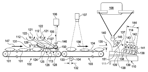
[0084] One embodiment of a system according to the invention will now be
described
with reference to Figure 1. First, a pillow bag 101 is positioned under a feed
forward unit 105 by
first input device 102. The pillow bag is non-rigid and has a thickness that
can vary from one
bag to another. The first input device is a device that moves, conveys or
propels the pillow bag.
For example, in some embodiments, the first input device comprises a conveyor
belt, rollers, or
chains. In Figure 1, the first input device 102 conveys the pillow bag 101 in
a first conveyance
direction 147.
[0085] Second, after the pillow bag 101 contacts the feed forward unit 105,
the feed
forward unit assists in moving the pillow bag, for example using a secondary
input device 124,
(e.g., a secondary conveyor belt, secondary rollers, or a driven overhead
conveyor belt) on the
bag-contacting surface of the feed forward unit 125. As the pillow bag is
propelled under the
feed forward unit, the position of the feed forward unit adjusts to
accommodate the thickness and
condition of pillow bag. For example, in Figure 1 the feed forward unit
comprises legs 121
which rotate in direction 112 around two axes of rotation 122. This rotating
motion adjusts the
position of the feed forward unit to accommodate the pillow bag, for example
by adjusting the
distance 126 between the bag-contacting surface 127 of first input device 102
and the bag-
contacting surface 125 of the feed forward unit 105. As viewed in Figure 1,
the two axes of
rotation are oriented perpendicular to the plane of Figure 1 (in other words,
the two axes of
rotation appear to be coming out of the page). In some embodiments, the
secondary input device
124 uses mechanical means to counter weight (e.g., springs, air cylinders,
etc.) and dampen (e.g.,
shocks, dash pot, air cylinder, etc.) the movement of the secondary input
device.
[0086] In one embodiment, the first input device 102 is a conveyor that
propels a non-
rigid pillow bag 101 into contact with a feed forward unit 105 so that the
pillow bag 101 pushes
up the feed forward unit 105. In one embodiment, the feed forward unit is
lightweight. In one
embodiment, the feed forward unit assists the conveyor to propel the pillow
bag. In one
embodiment, the feed forward unit uses a secondary input device 124 to propel
the pillow bag
101 at a speed that is nearly identical to the speed at which the first input
device 102 propels the
pillow bag.
[0087] In one embodiment, the feed forward unit 105 is attached to fixed
points which
provide axes of rotation 122 and the feed forward unit is free to rotate about
these fixed points.
This allows, for example, the feed forward unit to be pushed by the pillow bag
101 vertically
away from the first input device 102 and parallel to the direction 147 that
the first input device
conveys the pillow bag 101.
-17-
CA 02963064 2017-03-28
WO 2016/054561 PCT/US2015/053810
[0088] In one embodiment, the feed forward unit 105 comprises a vertical stop
that
maintains a gap between the feed forward unit and the first input device 102,
allowing the pillow
bag 101 to easily feed between the feed forward unit and first input device.
[0089] Third, as the feed forward unit 105 moves to accommodate the thickness
and
condition of the pillow bag 101 a distance sensor 106 measures the change in
vertical
displacement of the feed forward unit. In conjunction with a known initial
vertical position of
the feed forward unit, the change in vertical displacement of the feed forward
unit can be used to
determine the distance 126 between the bag-contacting surface 127 of first
input device and the
bag-contacting surface of the feed forward unit 125. This distance 126, in
turn, corresponds to
the thickness 128 of the pillow bag 101. The measurement of thickness 128 of
the pillow bag
101 or the measurement of at least one dimension sufficient to determine the
thickness 128 of the
pillow bag 101 is captured as recorded information. For example, the recorded
information can
be stored on a computer, USB flash drive, hard drive, CD, DVD, or any other
suitable computer-
readable information storage medium. In one embodiment, the recorded
information is stored in
a robot controller. In one embodiment, the recorded information is passed to
the robot controller
from the distance sensor while the presence sensor detects the presence of a
pillow bag.
[0090] In one embodiment, a flat surface 146 is mounted on the feed forward
unit 105
for measurement of the vertical position of the feed forward unit using a
laser distance sensor
106. In one embodiment, the distance sensor 106 is mounted to a fixed location
not on the unit.
In one embodiment, the distance sensor comprises a non-contact distance
sensor, a camera, laser,
light sensing device, or ultrasonic device.
[0091] In the embodiment shown in Figure 1, the thickness 128 of the pillow
bag 101 is
measured using a presence sensor 113, for example a bag presence sensor. In
one embodiment,
the presence sensor is a photo eye, for example, through-beam photo eye or a
capacitive or
photoelectric sensor. In one embodiment, the presence sensor can be used to
detect the position
of the pillow bag relative to the bag-contacting surface 127 of the first
input device 102. For
example, the presence sensor can detect when the leading (e.g. front) and
trailing (e.g. back)
edge of the pillow bag passes the presence sensor as it moves in the first
conveyance direction
147. In one embodiment, data from the presence sensor is sent to a robot
controller which uses
the information to determine the position of the leading and trailing edges of
the bag.
[0092] As the presence sensor senses the presence of the pillow bag 101 under
the feed
forward unit 105, for example, when the pillow bag blocks the field of vision
of the presence
sensor, the height of the feed forward unit is monitored and captured. In one
embodiment, this
height is sent to a robot controller. As the pillow bag passes under the feed
forward unit 105, the
height of the feed forward unit will adjust to accommodate the thickness and
condition of the
-18-
CA 02963064 2017-03-28
WO 2016/054561 PCT/US2015/053810
pillow bag. For example, the feed forward unit in Figure 1 has a tapered end
129 with a
secondary input device 124 to enable the passage under the feed forward unit
of any pillow bag
with a leading-edge height less than the maximum height of the tapered end
131. Additionally,
the feed forward unit 105 comprises a surface 150 substantially parallel to
the bag-contacting
surface 127 of the first input device 102. In the embodiment of Figure 1, the
surface 150 is also
substantially horizontal.
[0093] In some embodiments, the presence sensor 113 triggers a pick and place
robot
108 controller to log thickness measurements from the distance sensor 106.
Accordingly, in
some embodiments, the presence sensor 113 is located near the middle of the
surface 150 of the
secondary input device 124 when the feed forward unit 105 is resting on its
vertical stops. This
helps to ensure, for example, that thickness measurements for the pillow bag
101 are obtained
when a substantial amount (e.g. the majority) of the pillow bag 101 is being
conditioned
underneath the feed forward unit 105. This conditioning can be useful to
emulate the condition
of a bag when the end effector of the pick and place robot 108 picks the bag.
[0094] As first input device 102 propels the pillow bag 101 into contact with
the
secondary input device 124 on the bottom side of the tapered end 129 of the
feed forward unit
105, the pillow bag 101 will push up the feed forward unit 105 causing
vertical displacement of
the feed forward unit 105. Meanwhile, the presence sensor 113 will sense the
presence of the
pillow bag 101 under the feed forward unit 105. After the presence sensor 113
senses that the
pillow bag 101 has passed, the maximum value of vertical displacement of the
feed forward unit
105 caused by the pillow bag 101 is captured and used to determine a thickness
of the pillow bag
101. The thickness 128 of the pillow bag 101 is then captured, for example, by
storing the
information in a robot controller. In one embodiment, a photo-eye sensor 113
is used at the gap
between the feed forward unit 105 and the first input device 102 to detect the
presence of the
pillow bag 101 in order to capture the pillow bag's thickness 128.
[0095] Fourth, the pillow bag 101 is transported onto a second input device
103. The
second input device 103 conveys the pillow bag 101 in a second conveyance
direction 136.
Although the first conveyance direction 147 and the second conveyance
direction 136 can be the
same, they can also be different. In the embodiment shown in Figure 1, the
second input device
is directly coupled (1:1 mechanically, electrically or programmatically) to
the first input device
102. A first encoder 104 tracks the positional information of the second input
device 103. For
example, in Figure 1, the first encoder 104 is a wheel with a known radius 132
that turns around
a wheel axis of rotation 133 located at the center of the wheel. The wheel
contacts the bag-
contacting surface 134 of the second input device 103. In Figure 1, the bag-
contacting surface
134 of the second input device 103 is a conveyor belt. The surface of the
wheel exhibits a
-19-
CA 02963064 2017-03-28
WO 2016/054561 PCT/ES2015/053810
translational velocity that is equal to the translational velocity of the bag-
contacting surface 134.
Accordingly, the encoder can measure the translational change in position of
the bag-contacting
surface 134 at any particular time by measuring the translational change in
position of the
surface of the wheel at the same time. For example, if the wheel has turned N
times, then the
translational change in position of the surface of the wheel is equal to the
product of N times 2
times it times the known radius 132 of the wheel of the first encoder 104.
Although, in other
embodiments, the first encoder 104 tracks the position of the second input
device using other
appropriate approaches. In addition to an encoder, other devices can also be
used to track the
position of the second input device, for example, resolvers or other
rotational feedback devices
that provide position and/or velocity information over time.
[0096] The first encoder 104 is used to track the position information of the
second
input device 103 under a vision system 107. The vision system 107 senses, for
example, the
orientation of the bag and the two-dimensional position of the bag along the
plane of the bag-
contacting surface 134 of the second input device 103. In one embodiment the
vision system 107
comprises a grey scale camera that can identify key features of a bag to
determine its position
and orientation. In one embodiment, the vision system 107 is located in a
vision tunnel to block
out ambient light. In one embodiment, information regarding the pillow bag
101, for example,
the bag's orientation, position, and thickness, is determined and tracked by
the vision system
107, the first encoder 104, the presence sensor 113, and the distance sensor
106. In one
embodiment the information is then stored by a robot controller along with
times when the
information was collected. The robot controller can use the stored information
to position and
orient an end effector 145 on a robot 108 in order to pick the pillow bag 101
at a specific
location and time. The information can also be used by the robot controller to
reorient and
reposition the end effector 145 so that the pillow bag 101 conforms to a
desired pattern when it is
placed.
[0097] In Figure 1, the measurement of the thickness 128 of the pillow bag 101
is used
to position the end effector 145 a second height 135 above the surface of the
pillow bag 101 to
be picked, for example, 10 mm. Although, in other embodiments the second
height 135 can
vary. The second height 135 is selected to enable the robot 108 to effectively
and efficiently
pick the pillow bag 101. For example, if the robot uses a vacuum to pick the
product, the second
height 135 is small enough so that a robot 108 can grab the pillow bag using
suction created by
the vacuum. However, the second height 135 is large enough that the robot 108
is sufficiently
distant from the pillow bag 101 to avoid contacting the pillow bag 101 before
suction is
established by the vacuum. This can help prevent the pillow bag from being
damaged by the
robot 108. For example, the robot 108 could break the bag if the second height
135 is too small.
-20-
CA 02963064 2017-03-28
WO 2016/054561 PCT/US2015/053810
As another example, even if the second height 135 is greater than zero, if the
robot is not
positioned precisely and accurately at the second height 135, the robot 135
can damage the
pillow bag 101. Accordingly, it can be desirable to incorporate a tolerance in
the second height
135 to accommodate any inaccuracy or imprecision in the placement of the robot
108. In some
embodiments, the second height 135, including a tolerance, is 10 mm.
[0098] Although the robot 108 has been described as using a vacuum to pick the
pillow
bag 101, the robot 108 can also use pinchers, claws, magnetism, electrostatic
adhesion or other
suitable approaches to pick the pillow bag 101. If a vacuum is used to pick
the pillow bag, after
the pillow bag 101 is picked, the vacuum between the pillow bag 101 and the
robot 108 can be
checked to ensure that the robot 108 is securely holding the pillow bag 101.
For example, in one
embodiment, if a pressure sensor does not detect a sufficient vacuum in a
suction cup on the
robot 108, then the pillow bag 101 is not securely held by the robot 108. In
one embodiment, if
the pillow bag is not securely held, the robot will take corrective action,
for example, attempting
to create a better hold, not picking the pillow bag, not placing the pillow
bag in an array, or
rejecting the pillow bag. In some embodiments, the pillow bag is rejected by
using a robot to
place the bag down a chute within reach of the robot. It can be advantageous
for the chute to be
close to the robot so it takes less time and energy for a robot to move into
position to reject a
pillow bag and then return to a position for picking and placing pillow bags
in a pattern.
[0099] In some embodiments, the vision system 107 or a quality control system
can be
used to monitor the quality of pillow bags, which can be, for example, bags of
product on the
second input device 103. In one embodiment, if the bags do not satisfy quality
standards, they
are rejected, for example, by being allowed to travel off the end of the
second input device 103
or by being removed by a robot 108.
[00100] In one embodiment of the invention, at least one queue of information
regarding
the pillow bags 101 is generated. In one embodiment, a queue comprises
thickness information
for each pillow bag 101 whose thickness 128 has been measured. In one
embodiment, a queue
comprises information related to the position of each pillow bag that has been
detected by a
presence sensor 113. In one embodiment, a queue comprises information about
the thickness
128 of each pillow bag, and the position of each pillow bag 101 as measured
along a vector
parallel to second conveyance direction 136. For example, the position of each
pillow bag 101
in the second conveyance direction 136 can be determined using the position of
the bag-
contacting surface 127 for the first input device 102 when the pillow bag 101
is first detected by
presence sensor 113, last detected by presence sensor 113, or some combination
thereof The
position of the bag-contacting surface 127 for the first input device 102 can
be determined, for
example, from the position of the bag-contacting surface 134 for the second
input device 103 and
-21-
CA 02963064 2017-03-28
WO 2016/054561 PCT/US2015/053810
information regarding a relationship between the positions of the two bag-
contacting surfaces
127, 134. In one embodiment, the two bag-contacting surfaces are directly
coupled (e.g. 1:1
mechanically, electrically or programmatically). Additionally, information
regarding the
position of the bag-contacting surface 134 for the second input device 103 can
be determined
using the position of the first encoder 104 and information regarding the
relationship between the
position of the first encoder 104 and the position of the bag-contacting
surface 134 for the
second input device 103. For example, one such relationship can be the
circumference of the
wheel on the first encoder 104 and the length, perimeter or circumference of a
conveyor belt that
makes up the bag-contacting surface 134 for the second input device 103. Other
approaches for
determining the position of a pillow bag can also be used. For example, the
position can be
determined using an encoder for a motor used to drive a belt that transports
the bags.
[00101] In one embodiment, as a pillow bag 101 passes the presence sensor 113,
information regarding the approximate position of the pillow bag 101 as
measured along a vector
parallel to the second conveyance direction 136 is stored in a queue. Then as
the pillow bag 101
is detected by a vision system 107, the precise position of the pillow bag
determined as measured
along vectors parallel to and perpendicular to the conveyance direction 136.
In some
embodiments a more precise position of the pillow bag is measured along a
number of vectors,
for example, up to three vectors can correspond to the three-dimensional
position of a pillow bag
101 and one vector can correspond to time. In one embodiment, the time vector
corresponds to a
time when a particular position of the pillow bag 101 was detected.
[00102] In one embodiment, a first queue comprises information regarding the
thickness
128 of a pillow bag 101 and the approximate position of the pillow bag 101 as
measured along a
vector parallel to the second conveyance direction 136. For example, the first
queue can be
generated using information from the distance sensor 106 and the presence
sensor 113. A
second queue comprises information regarding the precise position of the
pillow bag 101 as
measured along vectors both parallel to and perpendicular to the conveyance
direction 136. For
example, the second queue can be generated using information from the vision
system 107.
Accordingly, the first and second queues both comprise coordinates for pillow
bags 101
corresponding to the position of the pillow bags 101 as measured along a
vector parallel to the
second conveyance direction 136. If a pillow bag in the first queue and a
pillow bag in the
second queue both have coordinates that are within a specified tolerance (e.g.
10 cm), then the
pillow bag in the first queue and the second queue are determined to be the
same pillow bag 101.
In this case, the position of the pillow bag 101 from the second queue is
merged with the
thickness 128 of the pillow bag 101 from the first queue to create a merged
queue coupling
thickness information with the most accurate and precise position information.
-22-
CA 02963064 2017-03-28
WO 2016/054561 PCT/US2015/053810
[00103] Although, this example has described positional information in two
queues
being merged when coordinates in the direction of conveyance match to a
specified degree, other
approaches could also be used. For example, the positional information from
two queues could
be merged based on any other measured coordinates that indicate that an
approximate position
and thickness of a bag in the first queue corresponds to a more precise
position of the bag in the
second queue.
[00104] In one embodiment, the robot 108 only picks a pillow bag 101 if the
information associated with that pillow bag satisfies certain criteria. For
example, in one
embodiment the robot 108 ignores a pillow bag 101 if information from a first
queue and
information from a second queue regarding the coordinates of the pillow bag
101 do not match
within a specified tolerance (e.g. 10 cm). As another example, the robot 108
ignores a pillow
bag if it is too close to another pillow bag or misshapen. For example, two
pillow bags can be
stuck together or too close to each other for the distance sensor 106 to
accurately measure the
thickness 128 associated with each pillow bag.
[00105] In one embodiment, information regarding a pillow bag 101, for example
the
thickness 128 and position of the pillow bag 101, is used to assign three-
dimensional coordinates
where the robot 108 picks the pillow bag 101. In one embodiment, a two-
dimensional position
of the bag along the plane of the bag-contacting surface 134 of the second
input device 103 is
provided by the vision system 107 and the thickness 128 of the pillow bag is
provided by the
distance sensor 106. Because the pillow bag 101 can be moving, for example
along the second
input device 103, the three-dimensional coordinates for picking the pillow bag
101 are selected
in part based upon where the pillow bag will be at the time the robot 108
reaches the three-
dimensional coordinates. For example, in one embodiment, information regarding
the thickness
of the pillow bag is acquired by a distance sensor 106 and transmitted to a
robot controller where
it is stored. Furthermore, information regarding the position of the pillow
bag is acquired from a
presence sensor 113 and transmitted to the robot controller where it is
stored.
[00106] As the robot controller receives information, it can save the
information along
with the time it was received. For example, in one embodiment, the robot
controller can create a
first queue with information regarding a pillow bag including the position of
the bag, the
thickness of the bag, and the time that the measurements were acquired. In one
embodiment, the
robot controller receives information regarding a more accurate position and
an orientation of the
pillow bag from a vision system and creates a second queue of information with
the more
accurate position of the pillow bag and the time it was obtained. In one
embodiment, the robot
controller receives information from an encoder 104 regarding the position of
the encoder, which
in conjunction with the time, can be used to determine the position of the
second input device
-23-
CA 02963064 2017-03-28
WO 2016/054561 PCT/US2015/053810
103 and the position of the pillow bag 101 on the second input device 103 at a
particular point in
time. In one embodiment, the robot controller creates a more accurate queue of
information for
the pillow bag 101 comprising the thickness 128 of the bag from the first
queue, the more
accurate position and an orientation of the bag from the second queue, and a
time associated with
the position of the bag. In one embodiment, the robot controller positions and
orients the end
effector 145 on a robot 108 to pick the pillow bag 101 at a particular time
and position based on
the information in the more accurate queue.
[00107] Fifth, after the robot 108 picks the pillow bag 101, the measurement
of the
thickness 128 of the pillow bag 101, can be used to accurately and precisely
place the pillow bag
101 on a universal surface 109 moving along a universal surface conveyor 110.
For example, in
Figure 1, the universal surface 109 is a tray and the universal surface
conveyor 110 is a tray
conveyor belt. The measurement of the thickness 128 of the pillow bag 101 can
be used to
position the robot 108 so that it accurately and precisely places the pillow
bag 101 in its place in
an array of pillow bags 137 to create a high quality pattern. In one
embodiment, a plurality of
robots can work together to form the array of pillow bags 137. For example,
this enables two
robots working at a given speed to form an array of pillow bags 137 as fast as
a faster robot
working at twice the given speed. In one embodiment, this enables energy
savings and cost
savings due to using less power consumption (or fuel) and lubrication and due
to less error in
picking and placing pillow bags.
[00108] In another embodiment, the resulting forces on the bags will be
reduced when
using multiple robots. For example, if a plurality of robots is used in place
of a single robot to
place product at a combined total rate, then the individual robots in the
multiple-robot-system
can accelerate at slower rates and still achieve the same combined total rate
of placement as the
single-robot system. If the rate the robots accelerate the bags is decreased,
then the force on the
bags will also be decreased because (in the absence of other forces) the force
on a bag is equal to
the mass of the bag times its acceleration. Additionally, using multiple
robots can decrease the
rate of angular acceleration on bags and therefore decrease torque on the
bags. In another
embodiment, two robots working together at a given speed can form an array of
pillow bags
twice as fast as a single robot working at the given speed. For example, in
some embodiments,
the conveyor belt or other input device can move pillow bags more quickly than
a single robot
can pick and place the pillow bags into an array of pillow bags. In some
embodiments a plurality
of robots work together to pick and place the pillow bags at speeds faster
than the speed of a
single robot. In some embodiment, a single robot can pick and place pillow
bags into an array of
pillow bags at a rate of at least about 60 pillow bags per minute, at least
about 80 pillow bags per
minute, or at least about 100 pillow bags per minute. In some embodiments, a
plurality of robots
-24-
CA 02963064 2017-03-28
WO 2016/054561 PCT/US2015/053810
can pick and place pillow bags at multiple times the rate of a single robot,
for example, 1.5
times, 2 times, 2.5 times, 3 times, 6 times, or 12 times the rate of a single
robot.
[00109] Generally speaking, the use of a plurality of robots in place of a
single robot is
potentially advantageous for several reasons. It can increase production
rates, lower the forces
required to control the bags, or both increase production rates and lower the
forces on the bags.
Accordingly, in some embodiments, the use of a greater number of robots in
place of a smaller
number of robots can be advantageous.
[00110] In one embodiment, a pattern creation cell can accommodate pillow bags
of
variable thicknesses. For example, in one embodiment, the pattern creation
cell comprises a
robot 108 that can accommodate pillow bags 101 of variable thickness 128
without the need for
operator intervention or adjustments to the pattern creation cell. In one
embodiment, the feed
forward unit 105 comprises a vertical stop that maintains a gap with a minimum
distance
between the feed forward unit and a first input device 102. If the minimum gap
distance and the
maximum height 131 of the tapered end 129 of the feed forward unit 105 are
properly sized for
the range of thicknesses that pillow bags 101 can exhibit, then the feed
forward unit 105 can
accommodate any pillow bags 101 or some subset of pillow bags 101 that contact
the feed
forward unit 105. For example, in one embodiment, the vertical stop is set so
that the minimum
gap distance is smaller than the thickness of all pillow bags or some subset
of pillow bags.
Accordingly, all pillow bags 101 will create a measurable change in the
elevation of the feed
forward unit 105 when the pillow bags contact the feed forward unit. In one
embodiment, the
vertical stop is set so that the minimum gap distance is sufficiently large to
accommodate all
pillow bags or a subset of all pillow bags. For example, in one embodiment, as
the minimum
gap distance is changed, the maximum height 131 of the tapered end 129 of the
feed forward unit
105 changes by an equal amount. Thus, in one embodiment, the maximum height
131 of the
tapered end 129 of the feed forward unit 105 can be set by setting the
vertical stop.
[00111] The array of pillow bags 137 comprises pillow bags of various
thicknesses that
are stacked so that the pillow bags are right-side up. In Figure 1, the
orientation of the pillow
bags in the array of pillow bags 137 is shown by bottom-to-top vectors 138
pointing from the
bottom to the top of each pillow bag. The bottom-to-top vectors 138 are
oriented perpendicular
to and away from the plane represented by the surface of the universal surface
109. The
thickness of each pillow bag is oriented parallel to the universal surface 109
and a first
placement vector 114.
[00112] The position of a pillow bag's 101 placement along the first placement
vector
114 depends on the thickness 128 of the pillow bag 101 and the thickness of
any other pillow
bags that have already been placed in an array of pillow bags 137 on the
universal surface 109.
-25-
CA 02963064 2017-03-28
WO 2016/054561 PCT/US2015/053810
For example, in Figure 1 the position of the pillow bag 101 along the first
placement vector 114
is determined using the measurement of the thickness 128 of the pillow bag 101
and captured or
saved information regarding the position of previously placed pillow bags in
the array of pillow
bags 137.
[00113] In one embodiment, the array of pillow bags is arranged according to a
pattern.
For example, the pattern can comprise pillow bags an-anged in a single plane
or a plurality of
planes. As another example, the pattern can comprise a plurality of pillow
bags, for example, 6,
18, 25, 36, or 50 pillow bags. In one embodiment, information regarding the
spacing, position, a
thickness, or some combination thereof is transmitted between robots and a PAC
or directly
between robots. In one embodiment, a robot picks and places pillow bags to
build an array of
pillow bags and passes information about the array of pillow bags to another
robot. Then,
another robot uses the information to pick and place pillow bags to contribute
to or modify the
array. In one embodiment, for example, a first pattern creation cell
comprising a first robot
builds a first 6x1 array of pillow bags and passes information about the first
array to a second
pattern creation cell comprising a second robot. Then, the second pattern
creation cell adds onto
the first 6x1 array of pillow bags by building a second 6x1 array of pillow
bags ncxt to the first
array. This process can continue until a grid, for example, a 2x3, 2x4, 3x5,
4x6, 5x10, 6x6 or
12x12 grid is constructed. Although, arrays and grids of various sizes can be
constructed using
various numbers of robots. In one embodiment, an array comprises only one row
or column. In
another embodiment, an array is an arrangement, for example, an ordered
arrangement.
[00114] In one embodiment, information is transmitted along a line of
communication,
for example, a line of electronic communication. In one embodiment the line of
communication
comprises, a wired connection, Ethernet connection, fiber optic connection,
wireless connection,
Bluetooth connection, radio connection, WiFi connection, a connection using
wireless telephone
standards, 1G, 2G, 3G, LTE, 4G, 5G, a connection using other technology, or
some combination
thereof. Although, in one embodiment a line of electronic communication can be
a power line.
In some embodiments, a line of communication directly transmits information
from one device
to another device. In some embodiments, a line of communication indirectly
transmits
information from one device to another device, for example, by transmitting
information from
one device to an intermediate device or devices and then to another device.
[00115] The universal surface conveyor 110 conveys the universal surface 109
in a
direction that is horizontal. As seen from any side, for example, as shown in
Figure 1, the
universal surface 109 is approximately in the shape of a wedge with a bottom
surface 139 that is
oriented horizontal and a top surface 140 that is oriented at a compound angle
from horizontal.
-26-
CA 02963064 2017-03-28
WO 2016/054561 PCT/US2015/053810
[00116] As shown in Figure 7A, which shows a universal surface 109 with the
positions
of supports 141 and 151 swapped relative to Figure 1, the top surface 140 is
parallel to a first
placement vector 114 which is at a first angle 167 away from horizontal and
points away from a
lowest corner 165 of the universal surface 109. The top surface 140 is also
substantially parallel
to a second placement vector 164, which is at a second angle 168 away from
horizontal. The
second placement vector 164 also points away from the lowest corner 165 of the
universal
surface 109. Together, the first and second angles 167, 168 of the first and
second placement
vectors 114, 164 provide the compound angle for the top surface 140 of the
universal surface
109.
[00117] Returning to Figure 1, a first support 141 extends perpendicularly
from the top
surface 140 of the universal surface 109. The first placement vector 114
points away from the
first support 141. A second support 151 also extends perpendicularly from the
top surface 140.
The second placement vector 164 (not shown in Figure 1, but depicted in Figure
7A) points away
from the second support 151. The lowest pillow bag 142 on the incline leans
against the first
support 141 and the second support 151 under the force of gravity. If the
bottom of the lowest
pillow bag 142 on the incline is placed too close to the first support 141,
the lowest pillow bag
142 can tilt and fall away from the incline under the force of gravity. If the
bottom of the lowest
pillow bag 142 is placed too far from the first support 141, the bottom of the
lowest pillow bag
can slip up the incline of the top surface 140, and the top of the lowest
pillow bag can slip down
the first support 141 under the force of gravity. Accordingly, the lowest
pillow bag 142 will tilt
and fall towards the first support 141. Thus, the lowest pillow bag 142 must
be accurately and
precisely placed and oriented with respect to the first placement vector 114
and the first support
141 to prevent the lowest pillow bag 142 from falling over. Furthermore, even
if the lowest
pillow bag 142 does not fall over, if it is not accurately and precisely
placed and oriented with
respect to the first placement vector 114, a poor quality pattern can result,
or other pillow bags,
which directly or indirectly lean against the lowest pillow bag 142 can fall.
For example,
because the second lowest pillow bag 143 leans against the lowest pillow bag
142, the second
lowest pillow bag 143 must be accurately and precisely placed and oriented
with respect to the
first placement vector 114 and the lowest pillow bag 142. As each additional
pillow bag is
placed in the array of pillow bags 137, it must also be accurately and
precisely placed and
oriented with respect to the first placement vector 114 and the previously
placed pillow bags. If
any pillow bag is inaccurately or imprecisely placed, it can create a poor
quality pattern. For
example, the pillow bags in the array of pillow bags 137 can fall over, the
pillow bags can fail to
be oriented right-side-up, the pillow bags can be damaged by the robot 108, or
the pillow bags
can otherwise fail to conform to the desired pattern or arrangement of the
pillow bags.
-27-
CA 02963064 2017-03-28
WO 2016/054561 PCT/US2015/053810
Analogous considerations are relevant with respect to the lowest pillow bag's
142 placement in
relation to the second support.
[00118] After the robot 108 has completed its portion of the pattern for thc
array of
pillow bags 137, a column height 144 for the universal surface 109 is given by
a distance along
the first placement vector 114 equal to the sum of the thickness of each
pillow bag and the gap
between each pillow bag in the array 137. In some embodiments, the robot 108
captures the
column height, for example, by measuring the column height 144 directly or
indirectly. The
column height 144 of the universal surface 109, and other captured information
regarding the
condition, dimensions, position, and orientation of the pillow bags in the
array of pillow bags
137 are stored (e.g., locally or remotely) by the robot controller and passed
to a programmable
automation controller (PAC) or programmable logic controller (PLC). The
information can be
used to position a robot 108 to place another pillow bag in the array of
pillow bags 137. For
example, at least one current column height can be transmitted from the PAC to
a control system
or a robot controller. Additionally, the PAC can share the information with
other pattern
creation cells. For example, after one pattern creation cell has completed a
pattern, the PAC can
transmit at least one current column height to a subsequent pattern creation
cell. In one
embodiment, the at least one current column height is used to calculate the
position where a
pillow bag should be placed to form a pattern. In one embodiment, after a
pillow bag is placed,
for example, in a column, the at least one column height associated with the
column is updated
by the robot controller. In one embodiment, after a pattern is completed for a
tray, all current
column heights are transmitted to the PAC. For example, the information
captured by the robot
controller regarding the array of pillow bags 137 can be transmitted to the
PAC.
[00119] In some embodiments a pattern creation line is formed from a plurality
of
pattern creation cells. For example, in some embodiments, each pattern
creation cell in a pattern
creation line creates a portion of a pattern on a universal surface.
Accordingly, in some
embodiments, each pattern creation cell places pillow bags to form part of a
pattern on the
universal surface and in so doing adds to the pattern created by previous
pattern creation cells
until the pattern is complete. Furthermore, in some embodiments a pattern
creation line
comprises a line PAC.
[00120] One embodiment of a pattern creation cell will now be described with
reference
to Figure 1. The pattern creation cell comprises equipment for picking and
placing pillow bags
in an array of pillow bags 137 according to a desired pattern. For example,
the pattern creation
cell shown in Figure 1 comprises a first input device 102, a feed forward unit
105, a presence
sensor 113, a distance sensor 106, a second input device 103, a first encoder
104, a vision system
-28-
CA 02963064 2017-03-28
WO 2016/054561 PCT/US2015/053810
107, a robot 108, a universal surface 109, a universal surface conveyor 110,
and a second
encoder 111.
[00121] The first input device 102 comprises a bag-contacting surface 127
which is used
to transport the pillow bag 101.
[00122] The feed forward unit 105 comprises legs 121 that rotate in direction
112
around two axes of rotation 122 and a bag-contacting surface 125 with a
secondary input device
124. The bag-contacting surface 125 comprises a tapered end 129 with a maximum
height 131.
[00123] The presence sensor 113 senses whether the pillow bag 101 is under the
feed
forward unit 105.
[00124] The distance sensor 106 directly or indirectly measures the thickness
128 of the
pillow bag 101. In some embodiments, the distance sensor directly or
indirectly measures a
measured distance between the feed forward unit and an input device, which
measured distance,
can be used, for example, to determine the thickness of a pillow bag.
[00125] The second input device 103 comprises a bag-contacting surface 134
that
transports pillow bags in the second conveyance direction 136.
[00126] The first encoder 104 comprises a known radius 132 and rotates around
a wheel
axis of rotation 133. The first encoder 104 tracks positional information
related to the second
input device 103 and can be used to track position information for the pillow
bags being
transported by the second input device 103. If the relative positions of the
second input device
103 and the first input device 102 are known, then the first encoder 104 can
also be used to track
positional information related to the first input device 103.
[00127] The vision system 107 comprises a 2D greyscale camera capable of
detecting
location and orientation of the pillow bags.
[00128] The robot 108 is capable of changing the orientation the pillow bags
that are
picked up. The robot 108 comprises an end effector 145. In some embodiment,
the end effector
108 changes the orientation of the plane of the bag, for example, from
horizontal to vertical. In
other embodiments, the end effector rotates the bag about an axis so that when
the bag is placed
it sits on a different surface than when it was picked.
[00129] The universal surface 109 comprises a bottom surface 139 that is
oriented
horizontal, and a top surface 140 that is oriented at a compound angle from
horizontal. The
universal surface 109 also comprises a first support 141 that is approximately
perpendicular to,
affixed to, and extends away from a first lower end of the top surface 140. In
some
embodiments, as shown in Figure 7A, the compound angle comprises a first angle
167 and a
second angle 168 such that one corner 165 of the universal surface 109 is
lower than all the other
corners. As shown in the embodiment of Figure 1, the lowest corner 165 is the
back right corner
-29-
CA 02963064 2017-03-28
WO 2016/054561 PCT/US2015/053810
(not visible) of the universal surface 109. In other words, as shown in Figure
1 the universal
surface 109 slants down, not only from left to right, but also from the front
to the back of the
page. In one embodiment, the universal surface 109 comprises a top surface 140
oriented at a
compound 20 degree incline from horizontal. In some embodiments, the compound
angle
comprises two angles and each of the two angles is greater than 0 , greater
than about 5 , greater
than about 15 , greater than about 200, greater than about 300, less than
about 900, less than
about 45 , less than about 300, or an angle selected from the range of about
00 to about 45 ,
about 100 to about 30 , about 15 to about 25 , or an angle selected from any
range whose end
points are selected from the endpoints of, or any point within, any of the
provided ranges. In
some embodiments, both angles are the same angle. In other embodiments, the
angles can be
different, even when both angles fall within the provided ranges.
[00130] In some embodiments, the compound angle of the universal surface 109
results
in a gravitational force on the bags that encourage them to justify against or
align along two
walls 141, 151. As shown in Figure 1, one of the two walls is the first
support 141. The other
wall is the second support 151 that is behind the array of pillow bags 137.
Like the first support
141, in some embodiments, the second support is approximately perpendicular
to, affixed to, and
extends away from a second lower end (not shown) of the top surface 140.
Although not every
bag touches the two walls, if a bag is not directly supported by the two
walls, it can lean against
another bag that is directly or indirectly supported by the walls. Further,
although one
embodiment of the invention has been described with reference to two fixed
walls, in some
embodiments the number of walls may be greater. For example, other
arrangements of walls
also have a lowest corner and can be used analogously. Other arrangements have
a lowest side
or edge and can also be used similarly, although they may not have a single
lowest corner. In
comparison to using a lowest corner, using a lowest edge does not typically
provide as much
support for maintaining the pillow bags in a desired position and orientation.
[00131] In the embodiment shown in Figure 1, the universal surface conveyor
110
comprises a rotary servomotor with a gearbox attached to a roller with a set
of sprockets. Each
sprocket drives a loop of chain. The universal surfaces 109 are affixed
between these loops of
chain. Although, the universal surface conveyor 110 can also take other forms,
for example, a
conveyor belt with a flat belt upon which a universal surface 109 can sit. In
other embodiments,
the universal surface conveyor 110 employs rollers, upon which the universal
surface 109 is
supported.
[00132] With reference again to Figure 1, the second encoder 111 tracks
position
information related to the universal surface conveyor 110 and can be used to
track position
information for the universal surface 109 and the array of pillow bags 137
being transported by
-30-
CA 02963064 2017-03-28
WO 2016/054561 PCT/US2015/053810
the universal surface conveyor 110. In one embodiment, the encoder 111 is
attached to a
servomotor (not shown) with a gear box (not shown) that drives a cylinder with
two sprockets
(not shown) that drive a pair of chains (not shown). Universal surface 109
attaches to the chains
so that as the chains move so does the universal surface 109. For example,
with reference to
Figure 1, universal surface 109 is traveling out of the page.
[00133] Figures IA-1C show an apparatus and method for picking a first pillow
bag
101a from a horizontal input device 102 and placing the first pillow bag 101a
in a desired
orientation in alignment with a compound angled universal surface 109. As
shown in a side
view in Figure IA, a vision system 107 measures the angle of a second pillow
bag 1011). As the
second pillow bag 10113 travels in a conveyance direction 136, it will reach
the position of the
first pillow bag 101a, where an end effector 145 picks the first pillow bag
101a. As the first
pillow bag 101a was conveyed to a pick location, the vision system 107 tracked
the first pillow
bag 101a.
[00134] When the first pillow bag 101a reaches the pick location, as shown in
Figure
1B, the vision system 107 commands the end effector 145 to be oriented at a
picking angle 160
relative to a supported side 169 of the first pillow bag 101a. Accordingly,
the end effector 145
picks the first pillow bag 101a at a picking angle 160 so that a rotation
about an axis 161
achieves a desired alignment of the supported side 169 of the first pillow bag
101a relative to a
supporting surface (e.g. sidewall 151) of the universal surface 109.
[00135] As can be seen in Figure 1C, when the first pillow bag 101a is placed
in the
universal surface 109, the supported side 169 of the first pillow bag 101a is
aligned with the
supporting surface (e.g. sidewall 151) of the universal surface 109.
[00136] As shown in Figures 1B and 1C, the picking angle 160 is substantially
equal to
an angle 168 of the universal surface 109 relative to horizontal and
substantially equal to an
angle 168 of the support 151 to vertical. Picking the first pillow bag 101a at
a picking angle 160
equal to the angle 168 of the support 151 relative to vertical is useful, for
example, when it is
desirable to have a lower side 169 of the first pillow bag 101a aligned (e.g.,
flush) with the
supporting surface 151 of the compound angled tray 109. Although aligning the
first pillow bag
101a with the supporting surface 151 is not always necessary, it can be useful
to provide
additional support for the first pillow bag 101a, for example, when creating
standup patterns in
which the first pillow bag 101a stands on a relatively thin edge 162. When it
is desirable to
place the first pillow bag 101a at an angle to the universal surface 109, the
picking angle 160 can
be adjusted accordingly.
[00137] Figure 1D shows an end effector 145 picking a pillow bag 101b from an
input
device 102. The target position for the pillow bag is a position adjacent to a
previously placed
-31-
CA 02963064 2017-03-28
WO 2016/054561 PCT/US2015/053810
pillow bag 101a in a compound angled universal surface 109. The target
alignment for the
pillow bag 101b is a standup alignment similar to the previously placed pillow
bag 101a.
[00138] To pick the pillow bag 101b, the end effector 145 is commanded to a
predefined
height 128 above the input device 102, which height corresponds to the
thickness (e.g., caused
by air fill) of the pillow bag 101b. The end effector 145 picks the pillow bag
(e.g. using suction
created by a vacuum nozzle 188 with bellows). If the thickness of the bag 101b
does not satisfy
a specification condition (e.g., being at least as large as a specified value)
then the bag 101b will
be rejected. For example, the end effector 145 can bring the bag 101b to a
rejection space 163
between an end of the input device 102 and the edge of the compound angled
universal surface
109 and release the bag. Alternatively, if the end effector 145 simply does
not pick the bag
101b, the bag will run off the input device 102 to the rejection space 163.
The bag 101b then
slides along ramp 179 to a location 177 in a reject bin 178.
[00139] Similarly, a vacuum sensor 187 measures the vacuum level achieved when
the
end effector 145 is in contact with the bag 101b. If the vacuum level is
insufficient to properly
control the bag for an accurate placement, then the end effector 145 releases
the bag into the
rejection space 163.
[00140] One embodiment of a method according to the invention will now be
described
with respect to Figure 2B. In a first step 210, each stock keeping unit
("SKIT) of bags is
provided with a specified thickness to determine air fill amount within a
certain tolerance.
Therefore, each SKU typically has an assumed thickness within this tolerance.
This enables the
operator to develop one assumed thickness for every bag in the batch. Second,
in an adjusting
step 212 the operator adjusts the pattern creation cell to accommodate bags of
the assumed
thickness. Third, in a conveying step 214, a bag from a batch with a given SKU
is conveyed on
a conveyor belt. Fourth, in a picking step 216, as each bag approaches a
robot, the robot picks
the bag using the assumed thickness from the specification step 210. Fifth, in
a placing step 218,
after the robot picks the bag, it places the bag in a first array, for
example, a line of bags. In
placing the bag, the robot again uses the assumed thickness. For example, the
assumed thickness
is used to estimate the position of previously placed bags and determine where
the bag should be
placed in relation to the other bags. Sixth, in a first repeating step 220,
the steps of conveying
214, picking 216, and placing 218 are repeated until the first array is
complete. Seventh, in an
optional expanding step 222, the first array is optionally expanded by using
another pattern
creation cell to add a second array to the first array to create an expanded
array or a grid. For
example, the first array can comprise one column of bags, while the expanded
array comprises
two columns of bags. Eighth, in a second repeating step 224, the step of
optionally expanding
-32-
CA 02963064 2017-03-28
WO 2016/054561 PCT/US2015/053810
the array is repeated until the expanded array matches a desired pattern. For
example, the
desired pattern can be in the form of a 3x3 grid of bags.
[00141] One embodiment of a method according to the invention will now be
described
with reference to the flowchart in Figure 3. First, in a measuring step 302, a
pattern creation cell
measures the thickness 128 of a pillow bag 101 that is moving on a conveyor
belt 102 to obtain a
measured thickness. In one embodiment, the measured thickness 128 is measured
directly or
indirectly using a distance sensor 106.
[00142] Second, in a transmitting step 304 the measured thickness 128 is
transmitted
directly or indirectly from the distance sensor 106 to a robot 108. In some
embodiments, the
measured thickness is transmitted from the distance sensor to a PAC and then
to the robot. In
other embodiments, the measured thickness is transmitted from the distance
sensor to a first
PAC, from the first PAC to a control system, from the control system to a
second PAC, and from
the second PAC to a robot. Other transmission paths are also possible.
[00143] Third, in a picking step 306, as each pillow bag 101 approaches a
robot 108, the
robot picks the bag using the measured thickness 128. In one embodiment the
pillow bag is
picked using an end effector 145 on the robot 108. In one embodiment, the end
effector 145
comprises a vacuum nozzle which creates suction between the robot 108 and the
pillow bag 101.
In one embodiment, the vacuum nozzle comprises flexible suction cups, and
bellows connect the
flexible suction cups to the end effector 145.
[00144] Fourth, in a placing step 308, after the robot 108 picks the bag 101,
it places the
bag according to a pattern to form a first array 137. In one embodiment, the
pattern is a line or
column of bags. In one embodiment, the measured thickness 128 is used to place
the bags and
maintain a desired pattern quality for the first array. In one embodiment, the
measured thickness
is used to conserve space in a package. For example, in one embodiment, the
measured
thickness is used to place the bag as close to previous bags as possible
without damaging bags or
negatively affecting the desired pattern quality.
[00145] Fifth, in a first repeating step 310, the steps of measuring 302,
transmitting 304,
picking 306, and placing 308 are repeated until the first array 137 is
complete.
[00146] Sixth, in an optional capturing step 312, the pattern creation cell
captures
information about the first array 137. For example, the pattern creation cell
can determine
information about the array, calculate information about the array, acquire
information about the
array, or perform some combination of these steps. In one embodiment, the
pattern creation cell
can capture information about an array by recording the location of the robot
108 as it places
pillow bags 101 in the array 137. In one embodiment, the pattern creation cell
captures at least
one column height 144 that is the sum of the thicknesses 128 of all the pillow
bags 101 in a
-33-
CA 02963064 2017-03-28
WO 2016/054561 PCT/US2015/053810
column in an array 137. In one embodiment, the pattern creation cell captures
information
related to the position, orientation, thickness, or some combination thereof
for at least one pillow
bag in an array. In one embodiment, the pattern creation cell captures
information related to the
position, orientation, thickness, or some combination thereof for each pillow
bag in an array.
[00147] Seventh, in an optional transmitting step 314, information about the
array 137 is
transmitted, for example, within a pattern creation cell, from one pattern
creation cell to another,
or using some combination thereof. In one embodiment, the information is
transmitted from one
device or system to another in a pattern creation cell, for example, from a
second encoder 111, a
distance sensor 106, or a robot 108 to a control system. It can be useful to
transmit information
about the array within a pattern creation cell to verify that the array
satisfies a desired pattern
quality. It can also be useful to transmit information within a cell to take
an appropriate action to
accept or reject an array depending upon whether it satisfies a desired
pattern quality. In another
embodiment, information about the array is transmitted from one pattern
creation cell to another
pattern creation cell. In yet another embodiment, information about the cell
is transmitted in
some combination of inter-cell and intra-cell transmission.
[00148] Eighth, in an optional expanding step 316, the first array 137 is
optionally
expanded by using another creation cell to add a second array to the first
array to create an
expanded array or a grid. For example, the first array can comprise one column
of bags 101,
while the expanded array comprises two columns of bags.
[00149] Ninth, in a second repeating step 318, the step of optionally
expanding the array
137 is repeated until the expanded array matches a desired pattern. For
example, the desired
pattern can be a grid of bags with multiple rows and columns.
[00150] Although the steps for the embodiment shown in Figure 3 have been
provided
in a particular order, the steps can be appropriately reordered in other
embodiments. For
example, in one embodiment, performing the optional transmitting step 314
occurs at multiple
points in a pattern creation process. Additionally, in some embodiments, not
all of the steps
shown in Figure 3 need to be present to perform a method according to the
invention. Likewise
although the steps for some embodiments (e.g. the embodiment shown in Figures
3A-3C) have
been provided in a particular order, the steps can be reordered in other
embodiments as
appropriate.
[00151] One embodiment of an apparatus and method according to the invention
will
now be described with reference to Figures 3A-3D. As shown in Figure 3A in a
first universal
surface conveying step 322, a universal surface conveyor conveys a universal
surface to a pattern
creation cell (e.g., pick and place cell). For example, Figures 1, 10, 11, 12,
13, and the
accompanying description describe examples of a universal surface conveyor.
-34-
CA 02963064 2017-03-28
WO 2016/054561 PCT/US2015/053810
[00152] Second, in a universal surface presence sensing step 324, the
universal surface
triggers a presence sensor for the universal surface. An example of a presence
sensor (e.g. for a
pillow bag, which could also sense other objects such as a universal surface)
is described in
Figures 1, 4, and 4A and the accompanying description.
[00153] Third, in a universal surface information acquisition step 326, a
pattern creation
cell controller for the pattern creation cell acquires information regarding
the universal surface,
for example, the position of the universal surface and at least one column
height for the universal
surface. For example, information regarding an object (e.g., a pillow bag or a
universal surface)
can be acquired as described in Figures 1, 1A-1D, 4, 4A, 4B, and the
accompanying description.
[00154] Fourth, in a second universal surface conveying step 328, the
universal surface
conveyor conveys the universal surface into an area of influence (A0I) for a
robot (e.g. pick and
place robot). For example, Figures 1, 10, 11, 12, 13, and the accompanying
text describe how an
object (e.g. a pillow bag or a universal surface) can be conveyed into the AOI
of a robot.
[00155] In some embodiments the universal surface comprises a compound angled
tray.
In some embodiments, the presence sensor for the universal surface comprises a
photo eye. In
some embodiments, during the universal surface information acquisition step
326, when the
universal surface triggers the presence sensor for the universal surface, a
pick and place robot
controller starts to continuously acquire information regarding the position
of the universal
surface from an encoder. For example, in some embodiments the pick and place
robot controller
acquires information regarding the universal surface (e.g., position) from the
pattern creation cell
controller. Furthermore, in some embodiments, during the universal surface
information
acquisition step 326, a pattern creation line PAC sends, via a communications
fieldbus, data
concerning the universal surface (e.g., current column height values) to the
pick and place robot
controller. For example, if the pattern creation cell is the first cell in a
pattern creation line, the
PAC sends zeros for all the column height values of the universal surface.
[00156] As shown in Figure 3B, in a first pillow bag conveying step 342, a
first input
device conveys a pillow bag to a feed forward unit of a pattern creation cell.
For example,
Figures 1, 10, 11, 12, 13, and the accompanying description describe examples
of input devices
(e.g. for pillow bags or universal surfaces).
[00157] Second, in a first pillow bag sensing step 344, the pillow bag
triggers a presence
sensor for the feed forward unit. An example of a presence sensor is described
in Figures 1, 4,
and 4A and the accompanying description.
[00158] Third, in a first pillow bag information acquisition step 346, a pick
and place
robot controller (e.g. a controller for a pick and place robot in the pattern
creation cell) acquires
information regarding the pillow bag from a distance sensor. For example,
information
-35-
CA 02963064 2017-03-28
WO 2016/054561 PCT/US2015/053810
regarding an object can be acquired as described in Figures 1, 1A-1D, 4, 4A,
4B, and the
accompanying description. In some embodiments the pick and place robot
controller directly or
indirectly acquires the thickness of the pillow bag from a distance sensor and
the position of the
pillow bag from an encoder. In some embodiments a pick and place robot
controller is the same
as a pattern creation robot controller and a pick and place robot is the same
as a pattern creation
robot. Accordingly, in some embodiments the terms can be used interchangeably.
[00159] Fourth, in a conditional verification step 348, the pick and place
robot controller
uses information regarding the pillow bag to determine whether the pillow bag
satisfies at least
one condition. Fifth, in a gatekeeping step 350, the pillow bag is rejected if
it does not satisfy
the at least one condition. For example, Figure 1D and the accompanying
description describe
an example of gate keeping or quality verification.
[00160] Sixth, in a second pillow bag conveying step 352, the pillow bag is
conveyed by
a second input device to a vision tunnel. Seventh, in a second pillow bag
sensing step 354, a
vision sensor senses information (e.g., position and orientation) regarding
the pillow bag.
Eighth, in a second pillow bag information acquisition step 356, a pick and
place robot vision
controller acquires information regarding the pillow bag from the vision
sensor. For example, a
vision system is described in Figures 1, 1A, 11 and the accompanying
description. Ninth, in a
pillow bag information transmission step 358, the pick and place robot vision
controller
transmits information regarding the pillow bag to the pick and place robot
controller.
[00161] Tenth, in an information comparison step 360, the pick and place robot
controller compares information from the pick and place robot vision
controller, on the one hand,
and the distance sensor and the encoder, on the other hand, to determine
whether the pillow bag
recognized by the pick and place robot vision controller can be associated
with a thickness of the
pillow bag. For example, in one embodiment if the position of the pillow bag
as determined by
the encoder and the vision sensor match within a specified tolerance, then the
two position
readings are deemed to correspond to the same pillow bag. Since a thickness
measurement from
the distance sensor is already associated with the position of the pillow bag
as determined by the
encoder, the thickness measurement is now also associated with the more
accurate position
determined by the vision sensor. Seventh, in a third pillow bag conveying step
362, the pillow
bag is conveyed into the pick and place robot's area of influence (A0I). For
example, Figures 1,
10, 11, 12, 13, and the accompanying text describe how an object can be
conveyed into the AOI
of a robot.
[00162] In some embodiments, the steps in Figures 3A and 3B occur
simultaneously.
For example, a universal surface can be conveyed to a pattern creation cell on
the universal
surface conveyor the same time that pillow bags are conveyed to the feed
forward unit and a
-36-
CA 02963064 2017-03-28
WO 2016/054561 PCT/US2015/053810
vision tunnel. In some embodiments it is efficient for the universal surface
to enter a pick and
place robot's area of influence (AM) before the pillow bags enter the robot's
AOT because the
pillow bags arc typically placed on the universal surface. Nonetheless, in
some embodiments the
invention can also accommodate scenarios where pillow bags enter the robot's
AOI before the
universal surface. For example, the input device for the pillow bags can pause
so that pillow
bags do not leave the robot's AOI before the universal surface enters the
robot's AOI and the
robot places the pillow bags on the universal surface. In some embodiments,
the invention can
accommodate scenarios where pillow bags enter the robot's AOT after the
universal surface. For
example, the input device for the universal surface can pause so that the
universal surface does
not leave the robot's AOI before the pillow bags enter the robot's AOI and the
robot places the
pillow bags on the universal surface.
[00163] In some embodiments, the presence sensor for the feed forward unit is
a photo
eye that is triggered when a pillow bag blocks the photo eye. For example, if
the photo eye is
located under the feed forward unit, and if the photo eye is blocked by a
pillow bag, then the
pillow bag is also under the feed forward unit.
[00164] In some embodiments, the first pillow bag information acquisition step
346
begins for a pillow bag when the pillow bag triggers a presence sensor and
ends when the
presence sensor can no longer detect the pillow bag. In some embodiments,
during the
conditional verification step 348, the pick and place robot controller uses
information from the
information acquisition step 346 to determine the thickness of a pillow bag,
the length of the
pillow bag, or both.
[00165] In some embodiments, during the conditional verification step 348, a
pillow bag
is rejected if it is too long, too short, too thick, or too thin.
[00166] In some embodiments, during the second pillow bag sensing step 354,
the vision
sensor is a 2-D camera. For example, in some embodiments as the pillow bags
are conveyed
through a vision tunnel they pass underneath the 2-D camera which acquires
information
regarding the pillow bag.
[00167] In some embodiments, during the second pillow bag information
acquisition
step 356, the robot vision controller acquires information from the 2-D
camera. In some
embodiments, the pick and place robot vision controller uses information
acquired by the 2-D
camera determine the 2-D position of a pillow bag and the orientation of the
bag.
[00168] In some embodiments, in a pillow bag information transmission step
358, the
pick and place robot vision controller passes the 2-D position of the pillow
bag and the
orientation of the pillow bag to the pick and place robot controller.
-37-
CA 02963064 2017-03-28
WO 2016/054561 PCT/US2015/053810
[00169] In some embodiments, during the information comparison step 360, the
pick
and place robot controller compares information received from the pick and
place robot vision
controller with information from the encoder of the feed forward unit to
associate each bag
recognized by the pick and place robot vision controller with height data from
the feed forward
unit. For example, in some embodiments pillow bag positional information from
an encoder is
associated with a thickness of the pillow bag at the feed forward unit. Then,
positional
information from the encoder is compared to 2-D position information from the
robot vision
controller. If the two positions match to a specified degree, the two
positions are deemed to
correspond to the same pillow bag and the thickness of the pillow bag as
measured by the feed
forward unit is combined with the more accurate position of the pillow bag
from the vision
controller.
[00170] Turning now to Figure 3C, in a picking step 382, the pick and place
robot
controller positions and orients the robot to pick the pillow bag using the
information regarding
the pillow bag from the pick and place robot vision controller (e.g., the
pillow bag's position and
orientation) and the feed forward unit (e.g., the pillow bag's thickness).
Second, in a placing
step 384, the pick and place robot controller positions and orients the robot
to place the pillow
bag on the universal surface in a desired position and orientation using the
thickness of the
pillow bag and the position and the at least one column height of the
universal surface. For
example, Figures 1A, 1B, 1C, 5A, 5B, 5C, 5D, and the accompanying text
describe how a robot
can pick and place an object (e.g. a pillow bag, plurality of pillow bags, or
layer of pillow bags).
[00171] Third, in a column height updating step 386, the pick and place robot
controller
obtains an updated column height for the column where the pillow bag was
placed. For
example, in one embodiment the column height is updated by adding the
thickness of the placed
bag to the column height of the column where the pillow bag was placed to
obtain an updated
column height.
[00172] Fourth, in a first repeating step 388, the pillow bag picking step
382, the pillow
bag placing step 384, and the universal surface column height updating step
386 are repeated
until the pattern creation cell has fulfilled its bag placement requirements
for a desired pattern.
[00173] Fifth, in a universal surface information transmission step 390, upon
completion
of placing the pattern creation cell's last bag for a desired pattern, the
pick and place robot
controller transmits information concerning the universal surface (e.g., at
least one column
height of the universal surface).
[00174] In some embodiments during the picking step 382, information regarding
the
pillow bag from the vision controller, for example, the 2-D position of the
pillow bag, the pillow
bag's orientation, or both, are used by the pick and place robot controller to
position and orient a
-38-
CA 02963064 2017-03-28
WO 2016/054561 PCT/US2015/053810
robot to pick the pillow bag. In some embodiments, the pillow bag is picked
(e.g., via vacuum) at
the con-ect elevation from a surface (e.g. conveyor belt) by using the
thickness of the pillow bag
from the feed forward unit.
[00175] In some embodiments during the placing step 384, the pick and place
robot
controller places the pillow bag at the correct position, depth, orientation,
or some combination
thereof on a universal surface using the thickness of the pillow bag, column
height values for the
universal surface, positional information for the universal surface, or some
combination thereof
For example, in some embodiments the pick and place robot controller places
the pillow bag
using column height values from the pattern creation line PAC for the
universal surface,
positional information from an encoder tracking the universal surface
conveyor, or both. In
some embodiments, the pick and place robot controller commands the pick and
place robot to
place the pillow bag on its bottom and so that it stands nearly perpendicular
to the top surface of
the universal surface. For example, if the pillow bag is picked using an end
effector in a first
orientation and a first orientation of the pillow bag is known, the end
effector on the robot can be
reoriented into a second orientation so that the pillow bag is also placed in
a second orientation.
Furthermore, in some embodiments the robot controller uses information
regarding the thickness
of the pillow bag and column heights of a universal surface (e.g. after any
previous pattern
creation cells have placed bags on the universal surface) to command the pick
and place robot to
place the pillow bag on the universal surface so that it stands nearly
perpendicular to the top
surface of the universal surface. For comparison, if a subsequently placed
pillow bag is placed
too far from or too close to a previously placed pillow bag, the pillow bag
can lean into or away
from that pillow bag, resulting in a non-perpendicular angle between the top
surface of the
universal surface and the pillow bag. Alternatively, if a non-perpendicular
angle between the
pillow bags and the universal surface is desired, if a subsequently placed
pillow bag is placed too
far from or too near to a previously placed pillow bag, the desired angle will
not be obtained and,
for example, the pillow bag could fall over or slip out of position.
[00176] In some embodiments, during the universal surface column height
updating step
386, only a single column height is updated, while in other embodiments a
plurality of column
heights are updated.
[00177] In some embodiments, during the first repeating step 388, a single
robot picks
and places the pillow bags on a universal surface while in other embodiments a
plurality of
robots pick and place bags on the universal surface. Furthermore, in some
embodiments during
the first repeating step 388, a single controller updates at least one
universal surface column
height after the placement of at least one pillow bag on the universal
surface. In other
embodiments during the first repeating step 388, a plurality of controllers
update at least one
-39-
CA 02963064 2017-03-28
WO 2016/054561 PCT/US2015/053810
universal surface column height after the placement of at least one pillow bag
on the universal
surface. In some embodiments, the first repeating step 388 is performed by a
single pattern
creation cell (e.g., a single pick and place cell).
[00178] In some embodiments, during the universal surface information
transmission
step 390, information regarding a pattern on a universal surface (e.g.,
compound angled tray) is
sent, via a communications fieldbus, from the pick and place robot controller
to the pattern
creation line PAC. In some embodiments the information regarding the universal
surface is used
by subsequent pattern creation cells to modify or add to the pattern on the
universal surface.
[00179] Turning now to Figure 3D, an apparatus and method for transferring a
pattern
from a universal surface to an ultimate package is described. First, in a
conveying step 391, the
pattern (e.g., a layer of pillow bags) on a universal surface is conveyed to a
pattern transfer
station. For example, Figures 11, 12, and 13 and the accompanying description
describe how a
universal surface can be conveyed to a pattern transfer station. Second, in a
picking step 392, the
pattern is picked by an end effector using vacuum. Third, in a placing step
393, the end effector
places the pattern in an ultimate package. For example, Figures 8A, 8B, 9, 11,
and 13 and the
accompanying description show an end effector and how it can be used to pick a
pattern from a
universal surface and place the pattern in an ultimate package.
[00180] Fourth, in an optional repeating step 394, the conveying step 391,
picking step
392, placing step 393, or some combination thereof are repeated until the
ultimate package is
filled with a desired pattern or plurality of patterns. For example, the end
effector can pick an
additional pattern from the universal surface or a subsequent universal
surface, and place the
additional pattern in an ultimate package. In some embodiments, the end
effector picks a first
layer of pillow bags and places the layer on a universal surface to form a
universal element.
Then, the end effector picks a subsequent layer of pillow bags and places the
subsequent layer on
a universal surface to form another universal element. Additionally, a first
pattern or layer of
pillow bags (e.g., a first universal element) can be placed in a first
ultimate package and a
subsequent pattern or layer of pillow bags (e.g., a second universal element)
can be placed in a
subsequent ultimate package. Although, in some embodiments, universal elements
can be
stacked on top of each other.
[00181] Fifth, in an optional transmitting step 395, information regarding the
ultimate
package, the plurality of ultimate packages, any pattern or layer associated
with an ultimate
package, or some combination thereof is transmitted. For example, the
information may be
transmitted to a pattern creation line PAC for use in transporting an ultimate
package to a
customer.
-40-
CA 02963064 2017-03-28
WO 2016/054561 PCT/US2015/053810
[00182] Although one embodiment of the invention has been described with at
least one
column height, in some embodiments, the universal surface is associated with
only a single
column height or a plurality of column heights. Although one embodiment of the
invention has
been described using a single universal surface conveyor, in some embodiments
a plurality of
universal surface conveyors are used instead of a single universal surface
conveyor. In some
embodiments, the universal surface is a tray or a compound angled tray.
[00183] Although one embodiment of the invention has been described using a
pattern
creation cell (e.g., pick and place cell) using a single robot to pick and
place pillow bags, other
embodiments use a plurality of robots to pick the pillow bags from a surface
and place the pillow
bags on a single universal surface. Although one embodiment of the invention
has been
described as using a vision sensor to sense information, for example, position
and orientation,
regarding the pillow bag, in other embodiments other sensors can be used. For
example, in some
embodiments, analogs to vision sensor can also be used so that the vision
sensor can be replaced
by any position and orientation sensor (e.g. acoustic, radar, etc.). Although
one embodiment of
the invention has been described as using an encoder, in some embodiments any
position sensor
can be used in place of an encoder.
[00184] Although one embodiment of the invention has been described as
comprising a
pick and place robot controller and a pattern creation cell controller, in
some embodiments, the
same controller can be used for both the pick an place cell and the pick and
place robot in the
pattern creation cell. Although one embodiment of the invention has been
described using a
controller of a certain type to accomplish a task, in other embodiments,
another controller, or a
plurality of controllers perform the same task. Although one embodiment of the
invention has
been described using a plurality of controllers to perform a plurality of
tasks, in some
embodiments, a single controller performs the plurality of tasks. For example,
a robot controller
can control a single robot or a plurality of robots. As another example, at
least one pattern
creation line PAC can be used to perform the role of at least one pattern
creation cell controller,
or vice versa. As another example, a pattern creation cell controller can be
used to perform the
tasks of a robot controller, or vice versa.
[00185] Although one embodiment of the invention has been described using a
specific
type of controller (e.g., pick and place robot controller, vision system
controller, a pattern
creation cell controller, pattern creation line controller) in other
embodiments a single controller
can perform the roles of a plurality of controllers or a plurality of
controllers can perform the role
of a single controller. Furthermore, in some embodiments a controller performs
additional roles,
a controller is present but performs no role, a controller is present but its
role is performed by
another controller, or a controller is not present. Also, although in some
embodiments
-41-
CA 02963064 2017-03-28
WO 2016/054561 PCT/US2015/053810
information is transmitted to a robot, in other embodiments the information is
transmitted to a
robot controller, and vice versa.
[00186] Although one embodiment of the invention uscs a plurality of input
devices, in
some embodiments a single input device is used.
[00187] One embodiment of an apparatus according to the invention will now be
described with reference to Figure 4. Generally speaking, the embodiment of
Figure 4 comprises
parts that were described with reference to Figure 1. However, the embodiment
of Figure 4
focuses on a portion of a pattern creation cell comprising a feed forward unit
105, a bag-
contacting surface 127 of a first input device 102, a presence sensor 113, and
a distance sensor
106. For example, the feed forward unit 105 of Figure 4 comprises a frame 149
which is
attached to rollers 148. A bag-contacting surface 125 (e.g. a conveyor belt)
rolls around the
rollers 148 and slides along the bottom of the frame 149. The frame 149 and
the rollers 148
guide the bag-contacting surface in a desired path. Although Figure 4 only
shows two rollers
148, more rollers can be used, for example, to guide the bag-contacting
surface or to reduce
friction. Additionally, the frame 148 can be formed in various shapes. For
example, the frame
148 can be any shape that comprises an end 129 suitable to receive pillow bags
101 and a surface
150 that is substantially parallel to a bag-contacting surface 127 of an input
device 102. The end
129 is suitable to receive pillow bags 101 and guide them between the bag-
contacting surface
127 of the input device 102 and the substantially parallel surface 150 of the
feed forward unit
105. A presence sensor 113 detects when a pillow bag 101 is between the bag-
contacting surface
127 and the substantially parallel surface 150. When a bag is between the two
surfaces 127, 150,
the thickness 128 of the pillow bag 101 is measured by detecting the distance
from a distance
sensor 106 to a flat surface 146 mounted on the feed forward unit 105. In the
embodiment
shown in Figure 4, the pillow bags 101 are conveyed in a first conveyance
direction 147.
[00188] One embodiment of an apparatus according to the invention will now be
described with reference to Figure 4A. Generally speaking, the embodiment of
Figure 4A
comprises parts that were described with reference to Figure 1. However, the
embodiment of
Figure 4A shows a feed forward unit 105 that differs from the feed forward
unit 105 shown in
Figure 1. For example, the feed forward unit 105 of Figure 4A comprises a
secondary input
device 124 that comprises secondary rollers.
[00189] Another embodiment of an apparatus according to the invention will now
be
described with reference to Figure 4B. Generally speaking, the embodiment of
Figure 4B
comprises parts that were described with reference to Figure 1. However, some
components
have been omitted to focus on changed components. For example, the embodiment
of Figure 4B
shows a feed forward unit 105 that differs from the feed forward unit 105
shown in Figure 1.
-42-
CA 02963064 2017-03-28
WO 2016/054561 PCT/US2015/053810
The feed forward unit 105 of Figure 4B comprises a first secondary input
device 124a and a
second secondary input device 124b. As a pillow bag 101 passes under the feed
forward unit
105, a distance sensor 106 (e.g., a transducer) is used to measure, directly
or indirectly, the
distance to the pillow bag. In some embodiments, the distance sensor is used
to measure,
directly, the distance to a bulge in the pillow bag 101 that develops at the
outer surface 402
between the first and second secondary input devices. The distance from the
sensor to the bulge
can be used to directly or indirectly measure the thickness of the pillow bag
101. For example, if
a bulge develops on the outer surface 402 where the thickness measurement is
taken, the
measured thickness can be further converted into a more accurate actual
thickness by
calculations, estimations, or reasonable assumptions.
[00190] In one embodiment, in order to properly condition the pillow bag 101
for
measuring thickness using a distance sensor 106, the feed forward unit 105
comprises a first
secondary input device 124a and a second secondary input device 124b that are
fixed in relation
to each other so that they are positioned the same distance from the first
input device 102. For
example, the first and second secondary input devices 124a, 124b can be fixed
in relation to each
other by being physically linked. In some embodiments, a pillow bag 101
passing under the feed
forward unit 105 contacts components of the feed forward unit 105 in the
following order: a
tapered end 129a of the first secondary input device 124a, a horizontal
surface 150a of the first
secondary input device 124a, a horizontal surface 150b of the second secondary
input device
124b, and a tapered end 129b of the second secondary input device 124b.
Accordingly, when
the thickness of a pillow bag 101 is being measured at a point of measurement
403 on the outer
surface 402 of the pillow bag 101, a portion of the outer surface 402a is in
contact with the
horizontal surfaces 150a, 150b of the feed forward unit 105 and an opposite
portion 402b of the
outer surface is in contact with first input device 102. In Figure 4B, the
contact between the
pillow bag 101 and the horizontal surfaces 150a, 150b occurs on opposing sides
of the point of
measurement 403. This serves to condition (e.g. flatten) the pillow bag 101 so
that a desired
thickness of the pillow bag 101 can be measured more accurately. For example,
the desired
thickness of the pillow bag 101 can correspond to the condition that the
pillow bag 101 will
experience when placed in a pattern by a pick and place robot.
[00191] In some embodiments, the distance sensor 106 directly or indirectly
measures a
distance across two opposite surfaces 402a, 402b of the pillow bag 101 to
provide a measured
dimension of the pillow bag 101. In some embodiment, the distance sensor 106,
measures the
distance to a surface 402 of the pillow bag 101 through a gap between two
portions (e.g., the first
and second secondary input devices 124a, 124b) of the feed forward unit 105.
-43-
CA 02963064 2017-03-28
WO 2016/054561 PCT/US2015/053810
[00192] Although the bags 101 have been described as passing under the
secondary
input device, in some embodiments this is not necessary. For example, in
addition to or in place
of using gravity to provide a force to position the feed forward unit 105 in
contact with the bags
101, a force can be provided, for example, by a spring, magnetism, or vacuum.
Likewise, other
forces or configurations can be used to maintain the bags 101 in contact with
the input device
102.
[00193] One embodiment of the invention will now be described with respect to
Figures
5A-5E, which provide an example of how pillow bags 101 can be picked from a
second input
device 103 and placed on a universal surface 109 to form an array of pillow
bags 137. First, in
Figure 5A an end effector 145 is positioned over a second input device 103 and
an array of
pillow bags 137 is arranged on a top surface 140 of a universal surface 109.
The array of pillow
bags 137 comprises a single column of pillow bags. The universal surface 109
is positioned on a
universal surface conveyor 110. Universal surface 109 comprises a bottom
surface 139, a top
surface 140, a first wall 141, and a second wall 151. The first wall 141 is a
finger wall. The
second wall 151 is a leading sidewall. The leading sidewall 151, the finger
wall 141, and the top
surface 140 come together to form a bottom corner (not shown) of the universal
surface 109. A
bag at the bottom corner leans against the first wall 141 and the second wall
151.
[00194] As can be seen in Figure 5A, in some embodiments the top surface 140
of
universal surface 109 is at a compound angle. In some embodiments, a support
post 166 is
attached to the top surface 140 and the bottom surface 139 to elevate one
corner of the top
surface 140 and provide the compound angle. As shown in Figure 5A, support
post 166 may be
fixed to a top corner of the top surface 140 and a portion of the bottom
surface 139. In some
embodiments, the bottom surface 139 is a frame with an empty interior, for
example, rather than
being in the form of a solid plane.
[00195] In Figure 5B, the second input device 103 has conveyed a pillow bag
101 into
the picking range of an end effector 145, and the end effector 145 has been
lowered into contact
with the pillow bag 101.
[00196] In Figure 5C, an end effector 145 has been positioned to place the
picked pillow
bag 101 in a second column of pillow bags next to a first column of pillow
bags, which have
already been placed. Together, the two columns of pillow bags form an array of
pillow bags
137. The array of pillow bags 137 rests on the universal surface 109
comprising a top surface
140, a sidewall 151, and a finger wall 141. The first column of pillow bags is
placed adjacent to
the sidewall. The end effector 145 is starting a second column that is
adjacent to the first column
by placing a pillow bag 101 against the finger wall 141 and next to the first
pillow bag 142 in the
first column. In some embodiments, a pillow bag can be placed in any
orientation with respect to
-44-
CA 02963064 2017-03-28
WO 2016/054561 PCT/US2015/053810
the universal surface so long as the bag is supported in the orientation (e.g.
as a result of gravity,
friction, the universal surface, other bags, etc.). As an example of a
possible orientation, a pillow
bag can be placed facing away from a universal surface wall (e.g., sidewall
151, finger wall 141),
facing toward a wall, and any angle in between while the bag stands on the
bag's end seal. As
another example, bags can be placed flat against the top surface 140 of the
universal surface
facing either toward or away from the universal surface.
[00197] Figure 5D shows the first pillow bag in the second column placed
adjacent to
the first column. The end effector 145 is once again positioned over the
second input device
103.
[00198] Figure 5E shows an array of pillow bags 137 arranged in a pattern on
the
universal surface 109. The array of pillow bags 137 are supported by a top
surface 140 and
directly or indirectly lean against a first wall 141 and a second wall 151.
The top surface 140 of
the universal surface 109 comprises a frictional coating 152. The frictional
coating increases the
friction between the top surface 140 and the pillow bags and helps prevent the
pillow bags from
slipping. In some embodiments, the frictional coating is a rubber mat, or a
textured surface (e.g.
surface with ribs, gnarling, aggregate coating, etc.).
[00199] Figures 6A - 6D show examples of patterns that can be formed with
pillow bags
in accordance with the present invention. The pillow bags 101 are placed on a
universal surface
109 starting with the lowest pillow bag 142, which is placed adjacent to the
lowest corner 165 of
the universal surface 109.
[00200] Turning to Figure 6B, an array of pillow bags is situated on a
universal surface
109 oriented with respect to a lowest corner 165 and two placement vectors
114, 164 extending
away from the lowest corner 165. The first placement vector 114 is parallel to
a top surface 140
and a sidewall 151 of the universal surface 109. The second placement vector
164 is parallel to
the top surface 140 and a finger wall 141 of the universal surface 109.
Although the two
placement vectors 164 and 114 are shown as perpendicular, they can also be at
some other angle.
[00201] The array of pillow bags on the universal surface 109 is arranged in a
pattern
having three columns 170, 171, 172 and six rows 180, 181, 182, 183, 184, 185.
Each column
170, 171, 172 is parallel to the first placement vector 114. Each row 180,
181, 182, 183, 184,
185 is parallel to the second placement vector 164.
[00202] The first column 170 is adjacent to and leans against the sidewall 151
of the
universal surface 109. Each subsequent column leans against and is adjacent to
the previous
column. For example, a second column 171 of pillow bags is adjacent to and
leans against the
first column 170. A third column 172 of pillow bags is adjacent to and leans
against the second
column 171.
-45-
CA 02963064 2017-03-28
WO 2016/054561 PCT/US2015/053810
[00203] A first row 180 of the array of pillow bags is adjacent to the finger
wall 141 of
the universal surface 109. Each subsequent row leans against and is adjacent
to a previous row.
For example, a second row 181 is adjacent to and leans against the first row
180. A third row
182 is adjacent to and leans against the second row 181. This pattern
continues for a total of six
rows.
[00204] Accordingly, the second lowest pillow bag 143 in the first column 170
and
along the first placement vector 114 leans against the lowest pillow bag 142
in the first column
170 and thus leans indirectly against the finger wall 141. Additionally, the
second lowest pillow
bag 143 in the first column 170 leans directly against the sidewall 151. Thus,
the second lowest
pillow bag 143 in the first column 170 is also the lowest pillow bag in the
second row 181.
[00205] Similarly, the second lowest pillow bag 143 in the first row 180 and
along the
second placement vector 164 leans against the lowest pillow bag 142 in the
first row 180 and
thus leans indirectly against the sidewall 141. Additionally, the second
lowest pillow bag 143 in
the first row 180 leans directly against the finger wall 141. Thus, the second
lowest pillow bag
143 in the first row 180 is also the lowest pillow bag in the second column
171.
[00206] As shown in Figure 6B, a pattern can comprise various kinds of bags
and can be
placed by a plurality of robots. For example, a first set 190 of bags is
placed by a first robot. In
Figure 6B, the first set 190 consists of the first row of pillow bags 180. A
second set 191 of bags
is placed by a second robot. In Figure 6B, the second set 191 consists of the
second row of
pillow bags 181. A third set 192 of bags is placed by a third robot. In Figure
6B, the third set
192 consists of the first column 170 of pillow bags, excluding the first two
rows. A fourth set
193 of bags is placed by a fourth robot. In Figure 6B, the fourth set 193
consists of the second
column 171 of pillow bags, excluding the first two rows. A fifth set 194 of
bags is placed by a
fifth robot. In Figure 6B, the fifth set 194 consists of the third column 172
of pillow bags,
excluding the first two rows.
[00207] In addition to showing a pattern placed by a plurality of robots,
Figure 6B also
shows a pattern that comprises a plurality of pillow bag types. For example,
the pattern in Figure
6B comprises four different types 600, 601, 602, 603 of pillow bags. The first
type 600 of pillow
bags is outlined with the letter "X". The second type 601 of pillow bags is
outlined with circles.
The third type 602 of pillow bags is outlined with dashes. The fourth type 603
of pillow bags is
outlined with squares.
[00208] Although Figure 6B shows one particular pattern of pillow bags, other
patterns
are also possible. In addition to patterns with three columns and six rows of
pillow bags,
patterns with more or less rows, more or less columns, or both are also
possible. For example, a
pattern can comprise a single row or a plurality of rows. A pattern can also
comprise a single
-46-
CA 02963064 2017-03-28
WO 2016/054561 PCT/US2015/053810
column or a plurality of columns. Likewise, patterns can comprise a single bag
type or a
plurality of bag types and patterns can comprises bags that are placed by a
single robot or a
plurality of robots.
[00209] Figures 6A and 6C-6D show elements that are analogous to the elements
shown
in Figure 6B, so every element will not be described. However, some of the
major differences
between Figure 6B and Figures 6A and 6C-6D will now be described.
[00210] Figure 6A shows a pattern of pillow bags that comprises two columns
170, 171,
four rows 180, 181, 182, 183, a single type 600 of pillow bags, and a
plurality of sets 190, 191,
192 of pillow bags that have each been placed by a different robot. Figure 6A
also depicts a
pattern that comprises a second column 171 of pillow bags in which each bag is
oriented at an
angle 611 to the first support 141 along a dimension 610 (e.g., length, width,
or height) of the
pillow bag. Meanwhile, the pattern also comprises a first column 170 of pillow
bags in which
each bag is oriented parallel the first support 141 along a dimension 610
(e.g., length, width, or
height) of the pillow bag. As can be seen in Figure 6A, in some embodiments a
row or pattern
according to the invention can comprise both bags that are at an angle to a
support along a
dimension and bags that arc parallel to the support along the dimension. An
array of pillow bags
can also be arranged in a pattern that comprises rows, columns, or both with
the same number of
pillow bags. Alternatively, a pattern can comprise rows, columns, or both with
varying numbers
of pillow bags.
[00211] Figure 6C shows a pattern of pillow bags that comprises six columns
170, 171,
172, 173, 174, 175 six rows 180, 181, 182, 183, 184, 185, three types 600,
601, 602 of pillow
bags, and six sets 190, 191, 192, 193, 194, 195 of pillow bags, each set
having been placed by a
different robot. For every row and every column in the pattern, each pillow
bag is oriented at an
angle 611 to a support (e.g., first support 141, second support 151, or both)
along a dimension
610 (e.g., length, width, or height) of the pillow bag.
[00212] Figure 6D shows a pattern of pillow bags that comprises five columns
170, 171,
172, 173, 174 five rows 180, 181, 182, 183, 184, five types 600, 601, 602,
603, 604 of pillow
bags, and six sets 190, 191, 192, 193, 194, 195 of pillow bags with each set
having been placed
by a different robot. As can be seen, the columns 170, 171, 172, 173, 174,
excluding the last row
(e.g. row five 184), were each placed by a different robot. In other words,
each column,
excluding the last row, consists of a set 190, 191, 192, 193, 194 of pillow
bags. The last row
(e.g. row five 184), consists of another set 195 of pillow bags. Each pillow
bag in the pattern is
oriented at an angle 611 to a support (e.g., first support 141, second support
151, or both) along a
dimension 610 (e.g., length, width, or height) of the pillow bag.
-47-
CA 02963064 2017-03-28
WO 2016/054561 PCT/US2015/053810
[00213] As can be seen with reference to Figure 6D, it can be advantageous for
a set
190, 191, 192, 193, 194, 195 of bags to comprise adjacent bags because, in
some cases, bags that
are placed close together can be more quickly placed by a single robot than
bags that are placed
further apart. Although Figure 6D shows each set 190, 191, 192, 193, 194, 195
as a full or
partial row or column, a set can also comprise bags arranged in other
configurations, for
example, in a plurality of rows and a plurality of columns. Although bags in a
set can be placed
adjacent to each other, a single robot can also place a set comprising bags
that are not all
adjacent. For example, in one embodiment, lower positions in a row and a
column are filled
before higher positions, but a plurality of robots fill the rows so that a
first robot can place a first
bag in a column or row, a second robot can place a second bag in the column or
row, and the first
robot can place a third bag in the column or row. Accordingly, the set of bags
placed by the first
robot can comprise bags that are not adjacent. Furthermore, using a plurality
of robots, bags in a
set placed by each robot can all be adjacent, can all be non-adjacent, or can
be both adjacent and
non-adjacent.
[00214] Although Figure 6A-6D showed columns that were perpendicular to the
first
support 141 and rows that were perpendicular to second support 151, the
columns and rows can
also be at an angle to a support, for example, to provide columns that are
diagonal or curved.
[00215] One embodiment of a universal surface 109 according to the present
invention
will now be described with reference to Figure 7A. The universal surface 109
comprises a first
support 141, a second support 151, a top surface 140, a lowest corner 165, and
a bottom 139.
[00216] The first support 141, the second support 151, and the top surface
140, come
together at a point to form the lowest comer 165. A first placement vector 114
and a second
placement vector 164 extend from the lowest corner 165 and along a second edge
and first edge,
respectively, of the top surface 140. The first edge is a line formed by the
intersection of the first
support 141 with the top surface 140. Likewise, the second edge is a line
formed by the
intersection of the second support 151 with the top surface 140.
[00217] In some embodiments, the first support 141 comprises a finger wall.
For
example, the finger wall can comprise a series of slats spaced apart a
distance to form openings
between the slats. In some embodiments, the second support 151 comprises a
solid sidewall.
[00218] As shown in Figure 7A, the top surface 140 of the universal surface
109 can be
at a compound angle. In some embodiments, the universal surface also comprises
a post 166 to
maintain the top surface 140 at the compound angle. The compound angle can
comprise a first
angle 167 and a second angle 168, which are angles between the first placement
vector 114 and
the second placement vector 164, respectively, and the bottom 139 of the
universal surface 109.
As shown in Figure 7A, the bottom 139 of the universal surface 109 is
horizontal, so the first
-48-
CA 02963064 2017-03-28
WO 2016/054561 PCT/US2015/053810
angle 167 and the second angle 168 are at an angle away from horizontal.
Additionally, the
placement vectors 114, 164 are perpendicular to each other, although in other
embodiments, the
vectors are at another angle to each other. As shown in Figure 7A, both the
top surface 140 and
the bottom 139 of the universal surface 109 are flat. In some embodiments, the
bottom 139 of
the universal surface 109 is solid. However, in other embodiments the bottom
139 of the
universal surface 109 is not solid. For example, the bottom can be a frame. In
some
embodiments, the bottom 139 of the universal surface 109, alone or in
conjunction with other
components, orients the top surface 140 at a compound angle. For example, the
bottom 139 and
post 166 can be used to maintain the top surface 140 of the universal surface
109 at a compound
angle. Although a post is used to provide a compound angle, in other
embodiments, the
compound angle can be provided in other ways, for example, by molding a
universal surface to
comprise a first surface at a compound angle to the bottom of the universal
surface. As another
example, the compound angle of the universal surface can be provided by
attaching (e.g. with
screws) the first surface to the bottom of the universal surface at an angle.
[00219] Figure 7B shows a schematic view of one embodiment of a universal
surface
that is a compound angled tray 109. In Figure 7B, the position of a finger
wall 141 and a solid
second support 151 have been swapped relative to Figure 7A. The universal
surface 109
comprises a first surface (e.g., top surface 140), a second surface (e.g.,
support 141) that is at a
90 degree angle to the first surface 140, and a third surface (e.g. second
support 151) that is
orthogonal to both the first surface 140 and the second surface 141. Although,
in this
embodiment the surfaces 140, 141, 151 are mutually orthogonal, in some
embodiments the
surfaces are not orthogonal to each other. The third surface 151 is slotted to
facilitate pattern
transfer, although in some embodiments the third surface is solid.
[00220] The three surfaces 140, 141, 151 are maintained in an attitude
relative to
horizontal. As shown in Figure 7B, horizontal corresponds with the bottom 139
of the universal
surface 109. The attitude of the tray 109 results in two angles 167, 168
relative to horizontal. As
shown in Figure 7B, the intersection of the first surface 140 with the third
surface 151 forms a
first vector 114 that points away from the bottom corner 165. The intersection
of the first
surface 140 and the second surface 141 forms a second a vector 164, which
points away from a
bottom corner 165 of the universal surface 109. The first vector 114 is at a
first angle 167 above
horizontal. The second vector 164 is at a second angle 168 above horizontal.
In some
embodiments, the vectors 114, 164 are mutually orthogonal. The two angles 167,
168 provide a
compound angle for the universal surface 109 and in addition to resulting in a
bottom or lower
corner 165, the compound angle also results in an upper or higher corner 165a.
-49-
CA 02963064 2017-03-28
WO 2016/054561 PCT/US2015/053810
[00221] Given the attitude of the universal surface 109 as a result of the
compound
angle, a pillow bag can be placed on the first surface 140 near the lower
corner 165 supported by
the second and third surfaces 141, 151 to provide, e.g., a bag in a standup
orientation.
Subsequent bags can be placed on the first surface 140, and can be supported
by a previously
placed bag or can be supported by one of the first or second surfaces 141,
151. The universal
surface 109 can be transported, for example, in a universal surface conveyance
direction 136a
positioning the universal surface 109 in range of multiple pattern creation
cells. Other directions
of travel of the universal surface 109 are possible, for example, as described
in Figures 12 and
13.
[00222] In one embodiment, as shown in Figure 7B, a universal surface is a
compound
angle tray. A high coefficient of friction surface 152 can be added to the
first surface 140 to
increase pillow bag stability during pattern creation and transportation. In
one embodiment, the
coefficient of friction is a static coefficient of friction that is high
enough to keep the object from
sliding when the first surface is at a compound angle of at least about 15 ,
at least about 20 , at
least about 30 , or at least about 45 from horizontal.
[00223] Figure 8A shows one embodiment of an end effector 800 for a pattern
transfer
robot, which in some embodiments comprises an articulated arm that is
connected to an adapter
plate 814. An adapter plate can be used to adapt robot tooling depending on
the pillow bags and
patterns that are being placed. For example, an adapter plate allows one robot
to adapt to form a
pattern because multiple end effectors fit the same adapter plate. By using an
adapter plate and
simply changing the end effector attached to the adapter plate, a robot can
pick and place bags in
a variety of patterns and in a variety of secondary packaging (e.g. ultimate
packages). A vacuum
input tube 813 provides vacuum to a plenum 818. As shown in the exploded view
in figure 8A,
the bottom of the plenum has holes 819. Although the holes 819 may be present
in a removable
panel, which forms the bottom of the plenum 818, the holes can also be on a
panel that is integral
with the rest of the plenum 818. Holes 819 (also shown in a plan view of the
bottom surface of
the plenum 818 in Figure 8C) allow the vacuum to gain control of one pillow
bag or a plurality
of pillow bags as the pattern transfer robot positions the end effector 800 in
close proximity to
pillow bags. Crowder plates 811, 812, and 817 constrain the at least one
pillow bag laterally to
facilitate entry of the at least one pillow bag into an ultimate package (e.g.
a cardboard box, a
sack, etc.). For ease of viewing, in Figure 8A a fourth crowder plate (e.g.
crowder plate 823 in
Figure 8B) has been removed from the side of the end effector 800 that is
facing the viewer. The
crowder plates 811, 812, 817, 823 articulate away from the at least one pillow
bag during the
picking step and then back into the at least one pillow bags for the transfer
or placing step. For
example, during articulation, crowder plate 817 is forced to rotate around
hinge 816 by actuator
-50-
CA 02963064 2017-03-28
WO 2016/054561 PCT/US2015/053810
815. When a pattern of pillow bags is transferred from a universal surface to
an ultimate
package, the pattern transfer robot picks the at least one pillow bag from the
universal surface
during a picking stcp. After the picking step, the crowder plates of the
pattern transfer robot
articulate toward the at least one pillow bag. Then, the pattern transfer
robot transfers the at least
one pillow bag to the ultimate package. As the at least one pillow bag is
placed in the ultimate
package during a transfer or placing step, the crowder plates act like a shoe
horn to help keep the
at least one pillow bag from splaying out. In some embodiments, without the
crowder plates, it
is more difficult to effectively, accurately, and consistently place pillow
bags in an ultimate
package. For example, the crowder plates prevent the at least one pillow bag
from hitting the
mouth of the ultimate package and being deflected outside the ultimate package
rather than being
placed inside the ultimate package.
[00224] Figure 8B shows the pattern transfer end effector with the crowder
plate 823
that was removed for clarity in Figure 8A. The end effector 800 is in a
picking position with
crower plate 823 shown in an open position. As shown in Figure 8B, a crowder
plate can be a
surface similar to the first surface 141 or second surface 151 of the
universal surface. For
example, a crowder plate can be a finger wall. As shown in Figure 8B, fingers
820 in crowder
plate 811 interface with fingers 821 of a universal surface 109 (e.g. compound
angled tray). This
finger interface between the end effector 800 and universal surface 109 allows
the path of the
end effector 800 as it departs from the pick position and travels to the place
position to be more
direct. This results, for example, in increased cycle times for picking and
placing using the
pattern transfer robot. The fingers in the end effector 800 also reduce the
frictional load between
the at least one pillow bag and the universal surface 109 (e.g. the force
between the at least one
pillow bag and the second surface 141 of the universal surface 109) thereby
reducing the force
required to be delivered by the vacuum plenum when picking the at least one
bag. Additionally,
the fingers in the end effector 800, because they can pass through the fingers
of the universal
surface, can simplify the process of transferring pillow bags from the
universal surface to an
ultimate package. For example, rather than needing to slide all the crowder
walls of the end
effector precisely between the walls of the universal surface and pillow bags,
crowder walls with
fingers can just pass through a corresponding finger wall of the universal
surface to help corral
the pillow bags for picking and/or transferring the pillow bags.
[00225] Figure 9 shows a side view of the universal surface 109 looking
parallel to the
second surface 151 with lower corner 165 shown on the right.
[00226] The fingers 821 of the universal surface are shown at a mating
orientation (e.g.
pitch) to the end effector 800 that is connected and controlled by a pattern
transfer robot.
-51-
CA 02963064 2017-03-28
WO 2016/054561 PCT/US2015/053810
[00227] At least one pillow bag will be resting on the first surface 140 and
supported by
the second and third surfaces 141, 151 as the end effector moves in direction
901. This motion
continues until the lower surface 902 of the cnd effector (e.g., lower surfacc
of plenum 818)
contacts the top of the at least one pillow bag and secures the at least one
pillow bag via the
vacuum 903 generated in a vacuum chamber (e.g. plenum 818).
[00228] As shown in Figure 9, the mating slotted fingers of the universal
surface 821
and end effector 820 allow, for example, the path of the end effector 800 to
go into the page
instead of having to lift up and over the second surface 141 of the universal
surface 109. The
resulting motion improves pillow bag control and improves transfer rates. If
the end effector or
universal surface had solid walls and the end effector took a path into the
page after being
lowered, the walls of the end effector and universal surface would collide
rather than slip past
each other.
[00229] Figure 10 shows a first input module 1001a feeding a first pillow bag
101c and
a second pillow bag 101d to a first pattern creation cell 1004a. The first
input module 1001a
comprises a first input device 102a and a second input device 102b, although
in some
embodiments the first input module 1001a comprises a single input device or a
plurality of input
devices. In some embodiments, the first pillow bag 101c and the second pillow
bag 101d are
different in type, in size, with regard to some other characteristic, or in
some combination
thereof. The first pattern creation cell 1004a receives the pillow bags 101c,
101d from the input
module and places them on universal surface 109 in desired patterns 137.
[00230] Subsequent input modules 1001b, 1001c and subsequent pattern creation
cells
1004b, 1004c work together to add pillow bags to a universal surface 109 until
the final input
module 100k feeds pillow bags 101e and 101f to the final pattern creation cell
1004c creating a
finished pattern 137b.
[00231] A universal surface conveyor 110 transports the universal surfaces 109
with the
completed patterns 137b to a pattern transfer station 1011 where the completed
patterns 137b are
removed from the universal surfaces 109 and placed into ultimate packages
1012.
[00232] An input module 1001a, 1001b, 1001c can feed a single pillow bag 101c,
101d,
101e, 101f to a pattern creation cell or feed a plurality of pillow bags.
Figure 10 shows an
embodiment where two types of pillow bags 101c, 101d are fed from a single
input module
1001a. More than two types of pillow bags can be fed from a single input
module if desired.
[00233] Figure 11 shows an embodiment of the invention for making multipacks
of
snack food bags that are placed in a pattern in an ultimate package that is a
caddie or case.
[00234] A first set of pillow bags 101a are transported by a first input
device 102a under
a first vision system 107a. The orientation and position of the first set of
bags 101a are
-52-
CA 02963064 2017-03-28
WO 2016/054561 PCT/US2015/053810
determined and tracked by the first vision system 107a such that a first delta
robot 108a can pick
the bags from the first input device 102a and place the bags on a universal
surface 109.
Subsequent sets of pillow bags 101b, 101c, 101d, 101e, 101f are handled by
subsequent input
devices 102b, 102c, 102d, 102e, 102f, vision systems 107b, 107c, 107d, 107e,
107f, and delta
robots 108b, 108c, 108d, 108e, 108f. The embodiment shown in Figure 11 uses
delta robots
108a, 108b, 108c, 108d, 108e, 108f that are Adept Quattro 650H robots.
Additionally, the
embodiment shown in Figure 11 comprises input modules which each comprise a
single input
device 102b, 102c, 102d, 102e, 102f.
[00235] The bags 101a, 100, 101c, 101d, 101e, 101f on the input devices 102a,
102b,
102c, 102d, 102e, 102f are flat but at random angular orientations. A first
delta robot 108 picks
a bag 101a in a flat condition, orients the angle of the bag, flips the bag
into a stand-up position
and then places the bag on a universal surface 109 to form a pattern. The
universal surface 109
travels in direction 136a and maintains the position and orientation of the
bag as subsequent
delta robots 108b, 108c, 108d, 108e, 108f add subsequent bags 101b, 10k, 101d,
101e, 101f, to
a pattern of bags until the pattern is completed after the final delta robot
108f places the final bag
or bags 101f.
[00236] In some embodiments, a robot 108a, 108b, 108c, 108d, 108e, 108f places
a
plurality of bags on a universal surface 109. Although, in other embodiments,
a robot places a
single bag on the universal surface 109.
[00237] The universal surface 109 transports the completed patterns to a
pattern transfer
station 1011. A pattern transfer robot 1122 removes the completed patterns
from the universal
surface 109. The embodiment shown in Figure 11 uses a pattern transfer robot
1122 that is a
Kawasaki RS3ON, 6-axis articulated arm robot. The pattern transfer robot 1122
places the
patterns into an ultimate package 1012, for example, a multipack case or
caddie supplied by a
first ultimate package conveyor 1121. Some of the ultimate packages 1012 are
used to package
multiple layers of bags. When an ultimate package 1012 is used to package
multiple layers of
bags, the ultimate package 1012 remains stationary as a pattern transfer robot
1122 loads the
required number of layers into the ultimate package 1012. In some embodiments,
an ultimate
package 1012 comprises a plurality of universal elements. A universal element
is a pattern in the
form of a layer. The universal element can be fed to the in-feed of a
packaging device (e.g., a
sacking, carting, or boxing machine) or can be loaded directly into an
ultimate package 1012. In
some embodiments, a second universal element is supported by a first universal
element that has
already been placed inside the ultimate package 1012. For example, each
universal element can
form a layer in a multi-layer pattern inside an ultimate package 1012. Once a
completed pattern
-53-
CA 02963064 2017-03-28
WO 2016/054561 PCT/US2015/053810
is loaded into the ultimate package 1012, the ultimate package is transported
away by a second
ultimate package conveyor 1123.
[00238] In some embodiments, the pattcrn transfer robot 1122 can remove
patterns from
the universal surface 109 and place them into an input device for a sack
machine. The sack
machine then completes the transfer of the pattern into a sack.
[00239] Although some embodiments have been described as using a single
conveyor,
various numbers of conveyors can be used. For example, in some embodiments,
ultimate
packages are conveyed by a single ultimate package conveyor. In other
embodiments, ultimate
packages are conveyed by a plurality of ultimate package conveyors.
[00240] Figure 12 shows an embodiment of a universal surface 109 where the
universal
surface 109 is a compound angled tray that is de-coupled from the universal
surface conveyor.
Universal surfaces 109 travel on reuse path 1286 and are inducted into a
universal surface filling
system (e.g., pattern creation line) at a reuse turn 1292. Universal surfaces
travel from a first
turn 1291 to a first decision point 1290. At the first decision point 1290 a
label reader 1295
identifies the universal surface. Although, a label reader (e.g., bar code
scanner) is used, other
approaches to identifying the universal surface can also be used. After the
universal surface has
been identified, it can be directed in various directions at a decision point,
depending on which,
if any, pillow bags still need to be added to a pattern on the universal
surface. At the first
decision point 1290, a turn can be rotated so that the universal surfaces can
be sent in a first
direction 1293a on a first pattern creation cell lane 1260 toward a first
pattern creation robot
108a or allowed to continue in a second direction 1293b that bypasses the
first robot 108a. In
some embodiments, the turn can comprise rollers, although other approaches can
also be used to
change the direction of a universal surface at a turn. For example, a conveyor
belt or a magnet
way with a linear motor (e.g., a linear induction motor) can also be used to
convey or change the
direction of a universal surface. As another example, the universal surface
can comprise a
magnet, (e.g., permanent magnet, or electromagnet such as an induction coil),
or a metal that
experiences a force in the presence of a magnetic field. If a universal
surface 109 is sent in the
first direction 1293a, the universal surface will continue to first pattern
creation cell 1287a where
the first pattern creation robot 108a will pick a desired number of bags from
each of the available
types of bags 101a, 101b, and 101c from a first input module 1001a and place
the picked bags
into the universal surface 109. The universal surface 109 will then continue
to second decision
point 1288. If more pillow bags are required to complete a pattern on the
universal surface 109,
then the universal surface is sent in a first direction 1293c to a Work-In-
Progress (WIP) lane
1285. From the WIP lane 1285, the universal surface 109 can be sent to a
subsequent pattern
creation cell lane 1261 toward a subsequent pattern creation robot 108b at a
subsequent pattern
-54-
CA 02963064 2017-03-28
WO 2016/054561 PCT/US2015/053810
creation cell 1287b. If the pattern is complete at the second decision point
1288 then the
universal surface 109 can be sent in a second direction 1293d to an express
lane 1294 for
transportation to a pattern transfer location. In some embodiments, once the
universal surface
109 reaches the express lane 1294, another turn 1289 can be used, for example,
to position the
universal surface 109 on a reuse path 1286. In one embodiment, only completely
empty
universal surfaces or universal surfaces with completed patterns are sent to
the express lane 1294
and any universal surface that is on the WIP lane 1285 or on a pattern
creation cell lane 1260,
1261, remains on a WIP lane or a pattern creation cell lane until a pattern on
the universal
surface is complete or the universal surface is emptied, for example, by a
pattern transfer robot at
a pattern transfer location. In some embodiments, the express lane provides a
more direct path
from one location to another as compared to the WIP lane. For example, the WIP
lane can
include more turns and decision points than the express lane. The WIP can also
experience
traffic jams, for example, where a universal surface returning from a pattern
creation cell and a
universal surface that by-passed the pattern creation cell can approach a
given location on the
WIP lane at the same time. Under these circumstances, the universal surfaces
can collide if one
conveyor is not paused. However, pausing a conveyor slows down the average
time at which the
WIP lane can convey products. Thus, even if the WIP lane and the express lane
convey products
at the same speed, the express lane can be used to convey a universal surface
with a finished
pattern to another location (e.g. pattern transfer station) more quickly.
Additionally, in some
embodiments, the express lane conveys products at a faster speed than the WIP
lane.
[00241] In some embodiments, a universal surface pattern does not include any
of the
types of pillow bags 101a, 101b, 101c at a first pattern creation cell 1287a
but does include at
least one or even all of the types of pillow bags 101d, 101e, 101f available
at a subsequent
pattern creation cell 1287b. If the final design for a pattern on a universal
surface includes
pillow bags from the subsequent pattern creation cell 1287b, the universal
surface will be sent to
the pattern creation cell 1287b.
[00242] Figure 13 shows an example of a decoupled universal surface 109 that
is
decoupled from a universal surface conveyor in conjunction with twelve pattern
creation robots
108a, 108b, 108c, 108d, 108e, 108f, 108g, 108h, 108i, 108j, 108k, 108m, with
each robot being
fed by an input module 1001a, 100lb, 1001c, 1001d, 1001e, 1001f, 1001g, 1001h,
1001i, 1001j,
1001k, 1001m using a triple in-feed system. In other words, each pattern input
module
comprises three input devices. Some of the equipment associated with the
twelve pattern
creation robots, input modules, first pattern creation lane 1260, subsequent
pattern creation lanes
1261, 1261c, 1261d, 1261e, 1261f, 1261g, 1261h, 1261i, 1261j, 1261k, 1261m,
%VIP lane 1285,
express lane 1294, reuse path 1286 and associated equipment was generally
described in Figure
-55-
CA 02963064 2017-03-28
WO 2016/054561 PCT/US2015/053810
12. Figure 13 shows, for example, how a decoupled universal surface can be
used with a
plurality of pattern creation cells.
[00243] As shown in Figure 13, a universal surface 109 is sent from a first
decision
point 1290 to appropriate pattern creation cells to receive a required
quantity of 36 available
types of pillow bags. Once a pattern on a universal surface is completed, the
universal surface
exits the WIP lane 1285 and enters the express lane 1294. The universal
surface exits the WIP
lane at a location (e.g., location 1398) and is sent to a first pattern
transfer station (e.g. first
pattern transfer station 1011). At the first pattern transfer location 1399,
the pattern can be
removed from the universal surface 109 and placed on an input device for a
sack machine 1302
by a pattern transfer robot 1122. Similarly at a subsequent decision point
1303 the universal
surface can be sent to a second pattern transfer station where a second
pattern transfer robot 1304
removes the pattern from the universal surface 109 and places the pattern into
a carton made by a
carton forming machine 1305. The universal surface can also be sent to a third
decision point
1306, where the pattern transfer robot can be sent to a third pattern transfer
robot 1307.
Additionally, the universal surface can be sent to a fourth decision point
1308, where the
universal surface can be sent to a fourth pattern transfer robot 1309. In some
embodiments, a
pattern transfer robot (e.g., the third and fourth pattern transfer robots
1307, 1309) remove the
pattern from the universal surface 109 and place the pattern into an Eaches
configuration in a
case that has been formed by an Eaches case erector 1310. Eaches
configurations can be
desirable because, for example, on a given production run each individual
Eaches configuration
can comprise any number of any type of product (e.g., multiple types of chip
products, or
different sizes of the same type of chip products). Meanwhile, for a given
multipack production
run, each multipack configuration has the same number, type, and arrangement
of products. In
other words, when using an Eaches production run, an ultimate package can
include products of
variable type, number, orientation, and position. Meanwhile, when using a
multipack production
run, each ultimate package includes the same mix, number, orientation, and
position of products,
although the number of units of the product can vary.
[00244] Eaches are especially useful for smaller customers who cannot order an
entire
pallet of a product, but would rather buy the product on an "each bag" basis.
Eaches product
configurations provide, for example, flexibility with respect to the type,
number, orientation, and
position of products on a universal surface and in an ultimate package. For
example, in some
embodiments, an Eaches order includes at least one product selected from the
group consisting
of products in a bottle, products in a can, products in the shape of bars,
products in pillow bags,
or some combination thereof. In some embodiments, the at least one product in
an Eaches
-56-
CA 02963064 2017-03-28
WO 2016/054561 PCT/US2015/053810
configuration has an orientation selected from the group consisting of, lying
on a side, lying on a
bottom, lying on a front, lying on a back, lying flat on a face, or some
combination thereof.
[00245] In some embodiments, ultimate packages (e.g. cases, cartons, sacks,
boxes, etc.)
are sent to a palletizing robot 1300, which places the ultimate packages in a
pallet.
[00246] In some embodiments a decoupled universal surface provides operational
flexibility by permitting universal surfaces that arrive on a single input
device to be directed to
any of a plurality of connected transfer stations. For example, in some
embodiments the same
universal surface conveyor can supply universal surfaces for the simultaneous
creation of
different types of ultimate packages, for example, sacks, cases, boxes,
cartons and caddies. In
some embodiments, the decoupled universal surface facilitates the automation
of a system for
taking, packaging, and delivering orders of product in an Eaches or multipack
configuration.
[00247] COMPARATIVE EXAMPLES
[00248] One embodiment of the invention provides for measuring a thickness of
a
moving pillow bag and using the measurement to pick and place the pillow bag.
In one
embodiment, the pillow bag is a bag of chips. In one embodiment, the pillow
bag has variable
dimensions and exhibits various conditions and orientations. For example, the
amount of air in a
bag can vary, and this can in turn, change the thickness of a bag. As another
example, the
direction that a bag is facing can vary.
[00249] In another embodiment, a pattern creation cell comprises an apparatus
for
measuring a thickness of a moving pillow bag and using that measurement to
pick and place the
pillow bag.
[00250] In one embodiment, a robot is used to pick and place the pillow bag
and the
robot is positioned using the measurement of the thickness. In one embodiment,
a pattern
creation cell is used to measure a thickness, position, and orientation of the
moving pillow bag
and pick and place the pillow bag in an array of pillow bags according to a
desired pattern. In
one embodiment, the pattern creation cell transmits information regarding the
thickness,
position, and orientation of the pillow bags in an array of pillow bags to
another pattern creation
cell. In one embodiment, pattern creation cells are used in conjunction to
form patterns. In some
embodiments, these patterns are complicated. For example, in some embodiments,
the patterns
comprise pillow bags 101 that are angled towards a wall of the universal
surface 140. In one
embodiment, a pattern comprises an array or grid of pillow bags. In another
embodiment, a
pattern comprises pillow bags stacked on top of each other along two or more
planes. In further
embodiments, the patterns comprise unique combinations of bag types and bag
quantities in each
pattern. In one embodiment, a pattern is described by a list of bag types and
quantities
associated with each type of bag.
-57-
CA 02963064 2017-03-28
WO 2016/054561 PCT/US2015/053810
[00251] In one embodiment a robot 108 places pillow bags 101 into a pattern
137 that
will fit into a box of known size (not shown). In creating the pattern 137,
the thickness 128 of
every bag 101 and any gaps between the bags are measured and added together
until a first
column height 144 equal to the box size is obtained, at which point a second
column is started.
In the embodiment of Figure 1, the second column would be placed in front of
the first column
which forms a part of the array 137. In other words, the second column is
placed out of the page
and toward the viewer in a way that would block the viewer's view of the first
column. In one
embodiment, this process of placing columns continues until the robot 108 has
finished the array
137. In other embodiments, additional robots can place columns, including for
example,
individual bags, to form the array 137.
[00252] In one embodiment, the invention creates tighter patterns of pillow
bags than a
traditional manufacturing, handling, or transportation apparatus or method.
For example, in one
embodiment, the tolerance (e.g. space) between bags in a pattern is selected
to be about 5 mm.
However, when using a manufacturing, handling, or transportation system with
assumed bag
thicknesses, the actual spacing between the bags can vary substantially from
the selected
tolerance of about 5 mm.
[00253] In one embodiment of the invention, downtime during a production run
is
decreased relative to a traditional manufacturing, handling, or transportation
apparatus, system or
method. In one embodiment, downtime is reduced by at least about 100 minutes
per day, 200
minutes per day, or 400 minutes per day. Although the actual amount of
downtime prevented
can vary depending on downtime per bag and the number of dropped bag events
per day in a
given traditional system and an embodiment of the invention. In one embodiment
of the
invention, substantially all down time due to dropped bags can be eliminated.
[00254] In one embodiment, the invention is a new and innovative apparatus
capable of
measuring the dimensions of a moving pillow bag and using that information to
pick and place
the pillow bag to form a high quality pattern, while simultaneously avoiding
damage to the
pillow bag. For example, in one embodiment, the invention is an apparatus that
measures the
height of a pillow bag on a running conveyor and can feed this height
measurement to a pick and
place system. In an additional embodiment, the pick and place system makes a
dynamic pick
and dynamic place using the measurement of a thickness of a pillow bag to
adjust both the pick
and place locations for the pillow bag. Accordingly, poor quality patterns,
inefficiency, damaged
product, and wasted product can be avoided while the accuracy, precision,
reliability and
efficiency of the pick and place system is simultaneously increased.
[00255] In another embodiment of the invention, an apparatus capable of
measuring the
position and dimensions of a moving pillow bag transmits information about the
position and
-58-
CA 02963064 2017-03-28
WO 2016/054561 PCT/US2015/053810
dimensions of the pillow bag to at least one other apparatus. For example, in
one embodiment, a
pattern creation cell with information about the position and dimensions of
pillow bags transmits
this information to at least one other pattern creation cell. In one
embodiment, a pattern created
by one pattern creation cell can be added to or modified by another pattern
creation cell. For
example, in one embodiment, a first pattern creation cell places at least one
pillow bag in a first
row on a tray, while a second pattern creation cell places at least one pillow
bag in a second row
that is adjacent to the first row. In one embodiment, pattern creation cells
are used in
combination to create more complicated patterns. This is desirable for the
flexibility it provides
with respect to designing patterns and the efficiency and cost-savings it
provides with respect to
reducing or eliminating misplaced and damaged product.
[00256] In one embodiment, the invention is a method comprising the steps of
conveying a pillow bag into contact with a feed forward unit, wherein the
contact causes a
change in the position of the feed forward unit to accommodate a thickness of
the pillow bag,
using a distance sensor to measure a change in position of the feed forward
unit, converting the
change in position of the feed forward unit into a measurement of the
thickness of the pillow
back, using the measurement of the thickness to pick the pillow bag, and using
the measurement
of the thickness to place the pillow bag in an array of pillow bags according
to a desired pattern.
[00257] In one embodiment, the method comprises the steps of using a pattern
creation
cell to form a first pattern by conveying a pillow bag into contact with a
feed forward unit,
wherein the contact causes a change in the position of the feed forward unit
to accommodate a
thickness of the pillow bag, using a distance sensor to detect a maximum
change in position of
the feed forward unit as a pillow bag passes under the feed forward unit,
converting the
maximum change in position of the feed forward unit into a measurement of the
thickness of the
pillow bag, using the measurement of the thickness to pick the pillow bag, and
using the
measurement of the thickness to place the pillow bag in an array of pillow
bags according to a
desired pattern; transmitting information about the array of pillow bags from
the first pattern
creation cell to a second pattern creation cell, and using the second pattern
creation cell to form a
second pattern that uses or incorporates the array of pillow bags from the
first pattern.
[00258] In one embodiment, the method comprises the steps of conveying a
pillow bag
into contact with a feed forward unit, wherein the contact causes a change in
the position of the
feed forward unit to accommodate the thickness of the pillow bag, using a
presence sensor to
determine when the pillow bag begins and ceases to cause a change in the
position of feed
forward unit, using a distance sensor to continuously measure the change in
position of the feed
forward unit, capturing the maximum change in position of the feed forward
unit caused by the
pillow bag, converting the maximum change in position of the feed forward unit
into a
-59-
CA 02963064 2017-03-28
WO 2016/054561 PCT/US2015/053810
measurement of the thickness, using the measurement of the thickness to pick
the pillow bag,
and using the measurement of the thickness to place the pillow bag in an array
of pillow bags
according to a desired pattern.
[00259] In one embodiment, a conveyor belt propels a non-rigid pillow bag into
contact
with a feed forward unit so that the pillow bag pushes up the feed forward
unit. The feed
forward unit is lightweight and also assists the conveyor to propel the pillow
bag. The feed
forward unit assists by using rollers to propel the pillow bag at a speed that
is nearly identical to
the speed at which the conveyor propels the pillow bag. The feed forward unit
is attached to
fixed points and the unit is free to rotate about these fixed points. This
allows the unit to be
pushed by the pillow bag vertically away from the conveyor and parallel to the
direction of
motion of the conveyor. The feed forward unit comprises a vertical stop that
maintains a gap
between the unit and the conveyor, allowing the pillow bag to easily pass
between the unit and
conveyor. A flat surface is mounted on the feed forward unit for measurement
of the vertical
position of the unit using a laser distance sensor. The laser distance sensor
is mounted to a fixed
location not on the unit. A photo-eye sensor is used on the gap between the
feed forward unit
and conveyor to detect the presence of the pillow bag in order to capture the
pillow bag's
thickness.
[00260] Although the invention has generally been described, for example in
Figure 1,
using a particular laser sensor to measure distance, and hence the thickness
128 of pillow bags
101, alternative distance sensors can also be used, for example, a camera,
laser, light sensing
device, ultrasonic device, or other non-contact distance sensors. For example,
in one
embodiment, assuming a bag is conditioned well (e.g., lack of crinkles or fold
overs), the bag can
be conveyed under a 3D line scanner to create a profile of the bag and provide
a planar map of
the bag with respect to the surface of a conveyor for the bag. The planar map
can in turn be used
with planar matching, vision tools, or calculations to determine the thickness
of the bag.
[00261] Additionally, the invention has generally been described, for example
in Figure
1, using contact to measure the thickness 128 of pillow bags 101. For example,
a first surface of
a pillow bag 101 is in contact with a first input device 102 and a second
surface of the pillow bag
101 is in contact with a secondary input device 124. In Figure 1, the distance
between these two
contact points can be used to measure the thickness 128 of the pillow bag 101.
However, in
other embodiments, noncontact approaches for measuring thickness can also be
used. For
example, at least one distance sensor can be used to map, in whole or in part,
directly or
indirectly, at least one surface of a pillow bag 101. For example, in one
embodiment, a three-
dimensional ("3D") camera can be used to map the at least one surface of a
pillow bag 101. By
calculation, estimate, reasonable assumptions, or some combination thereof,
information
-60-
CA 02963064 2017-03-28
WO 2016/054561 PCT/US2015/053810
regarding the at least one surface of the pillow bag 101 can be converted into
a volume of the
pillow bag 101 at certain conditions. In turn, by calculation, estimate,
reasonable assumptions, or
some combination thereof, the volume of a pillow bag 101 at certain conditions
can be converted
into a thickness 128 of the pillow bag. Generally speaking, because the pillow
bag 101 is non-
rigid, the thickness 128 of the pillow bag at any given location along its
length will depend on
the shape of the pillow bag. For example, the thickness 128 of a pillow bag
101 that is relevant
for placing the pillow bag in an array of pillow bags 137 is the maximum
thickness that the
pillow bag will have in the array. For example, this can determine how closely
pillow bags can
be placed to each other. Accordingly, the shape that a pillow bag will have in
a pattern can be
used to calculate or estimate the relevant thickness of the pillow bag in the
pattern.
[00262] Further, the invention has generally been described, for example in
Figure 1,
using encoders 104, 111 to track positional information that can be used, for
example, to
determine the location of a pillow bag 101 or an array of pillow bags 137.
However, in some
embodiments of the invention other devices are used to track positional
information, for
example, a rotational feedback device that can provide position and velocity
information over
time.
[00263] In addition, the invention has been described, for example in Figure
1, using a
programmable automation controller (PAC) as a control platform for
communicating between
various components, for example, robot controllers. However, in some
embodiments other
control platforms can also be used, including, but not limited to, a
programmable automation
controller (PAC), a programmable logic controller (PLC), a personal computer
(PC), an
industrial PC, a handheld computing device, a mobile computing device, a
tablet computer, or a
smart phone.
[00264] Furthermore, the invention has been described, for example in Figure
1, using a
first input device 102 and a second input device 103. However, in other
embodiments a different
number of input devices can be used, for example, a plurality of input devices
or a single input
device.
[00265] Additionally, in some embodiments the first support 141 which extends
perpendicularly from the top surface 140 of the universal surface 109 can be a
finger wall. For
example, the first support 141 can comprise a series of fingers with gaps
between them. In some
embodiments, this allows a component with matching fingers and gaps on an end
effector 145 of
a robot 108 to pass through the finger wall 141 without having to be raised
above the finger wall.
For example, this can increase the efficiency of picking and placing pillow
bags 101 in array
pillow bags 137.
-61-
CA 02963064 2017-03-28
WO 2016/054561 PCT/US2015/053810
[00266] In some embodiments, the invention provides an apparatus and method
for
measuring a dimension of a non-rigid object and using the dimension to pick
and place the
object. A first input device conveys a non-rigid object into contact with a
feed forward unit,
which contact causes a displacement of the feed forward unit. The displacement
measures a
dimension of the object. The measured dimension is transmitted via at least
one line of
communication.
[00267] In some embodiments, the invention provides an apparatus and method
for
measuring a dimension of a non-rigid object and using the dimension to pick
and place the
object. A first input device conveys the object into contact with a feed
forward unit, which
contact conditions the object. A distance sensor is positioned over a gap in
the feed forward unit
to measure a distance to a surface of the conditioned object. The distance
measures a dimension
of the conditioned object. The measured dimension is transmitted via at least
one line of
communication.
[00268] In some embodiments, the invention provides an apparatus and method
for
maintaining a pattern of non-rigid objects in a desired position and
orientation. The first
surface, second surface, and third surface are mutually orthogonal and meet at
a point to form a
lowest corner. The second and third surfaces are supported by, attached to and
extend at least
somewhat vertically from the apparatus. The first surface is oriented at an
angle to a plane
running through a bottom of the apparatus and thereby provides the lowest
corner.
[00269] In some embodiments, the invention provides an apparatus and method
for
transferring a pattern from a universal surface to an ultimate package. The
apparatus comprises
an end effector for a pattern transfer robot. The end effector comprises a
crowder plate with
crowder plate slats spaced apart a distance to form openings between the
crowder plate slats.
The universal surface comprises a finger wall with finger wall slats spaced
apart a distance to
form openings between the finger wall slats. A portion of the crowder plate
slats are sized to
pass between a portion of mating finger wall slats.
[00270] Example 1
[00271] Tn Example 1, an embodiment of the invention was tested using two
columns of
bags. The first column of bags comprised bags approximating thick bags. These
thick bags
were actually two bags taped together so that they were approximately twice
the thickness of a
single bag. The second column of bags approximated normal bags. These normal
bags
comprised single bags. When the two columns were tested using a traditional
handling system,
the robot popped the third thick bag to be picked and placed. However, when
the two columns
were tested using an embodiment of the invention, both the thick bags and the
normal bags were
accurately picked and placed by the embodiment without popping bags.
Additionally, the
-62-
CA 02963064 2017-03-28
WO 2016/054561 PCT/US2015/053810
embodiment, measured, picked and placed both columns of bags without being
manually
adjusted after the first column and before the second column. In some
embodiments, a robot can
accurately measure, pick and place bags with variable thicknesses such that
the thickest bag is
three times the thickness of the thinnest bag. For example, in one embodiment
a robot can
accurately measure, pick and place bags with thicknesses that vary from about
20 mm to about
60 mm. In other embodiments, the invention can accurately measure, pick and
place bags with
thicknesses that vary over even greater ranges. In other embodiments, there is
essentially no
limit on the thickness range of bags apart from that imposed by robot
characteristics (e.g. reach).
[00272] Although various components have been described herein in terms of
being
parallel, perpendicular, right-side-up, at an angle, or otherwise oriented, in
some embodiments
the components are only substantially parallel, perpendicular, right-side-up,
at an angle, or
otherwise oriented. In other embodiments the components are only approximately
parallel
perpendicular, right side up, at an angle, or otherwise oriented.
[00273] While this invention has been particularly shown and described with
reference
to preferred embodiments, it will be understood by those skilled in the art
that various changes in
form and detail can be made therein without departing from the spirit and
scope of the invention.
The inventors expect skilled artisans to employ such variations as
appropriate, and the inventors
intend the invention to be practiced otherwise than as specifically described
herein.
Accordingly, this invention includes all modifications and equivalents of the
subject matter
recited in the claims appended hereto as permitted by applicable law.
Moreover, any
combination of the above-described elements in all possible variations thereof
is encompassed
by the invention unless otherwise indicated herein or otherwise clearly
contradicted by context.
ADDITIONAL EMBODIMENTS
[00274] Various additional embodiments of the invention will now be described.
The
following clauses are presented, for example, as a further description of the
disclosed
technologies and inventions herein.
-63-
CA 02963064 2017-03-28
WO 2016/054561
PCT/US2015/053810
1. An apparatus for use in picking and placing a non-rigid object, said
apparatus
comprising:
a first input device;
a feed forward unit; and
at least one line of communication;
wherein the first input device conveys a non-rigid object into contact with
the feed
forward unit, which contact causes a displacement of the feed forward unit,
wherein the displacement measures a measured dimension of the object, and
wherein the measured dimension is transmitted via the at least one line of
communication.
2. The apparatus of clause 1, further comprising:
a distance sensor, wherein the distance sensor measures the measured dimension
of
the object by measuring the displacement of the feed forward unit.
3. The apparatus of clause 2, wherein the distance sensor measures a
measured distance
between the feed forward unit and the input device while the object is in
contact with the feed
forward unit, and wherein the measured dimension is substantially equal to the
measured
distance.
4. The apparatus of clause 1 further comprising:
a robot, wherein the robot is positioned to pick and place the object using
the
measured dimension, and wherein the measured dimension is transmitted to the
robot via the
at least one line of communication.
5. The apparatus of clause 4, wherein the robot is positioned a specified
distance above
an object-contacting surface of an input device to pick the object from the
object-contacting
surface, and wherein the specified distance is at least as large as the
measured dimension.
6. The apparatus of clause 1, further comprising:
a presence sensor; wherein the presence sensor detects a presence of the
object.
7. The apparatus of clause 6, wherein the presence sensor detects a
position of the
object.
8. The apparatus of clause 6, wherein a distance sensor measures the
measured
dimension of the object by measuring a measured distance between the feed
forward unit and
the input device while the presence sensor detects the presence of the object
between the feed
forward unit and the input device.
9. The apparatus of clause 1, wherein a distance sensor measures a measured
distance
between the feed forward unit and the input device while the object is in
contact with the feed
-64-
CA 02963064 2017-03-28
WO 2016/054561
PCT/US2015/053810
forward unit; and wherein the measured dimension is substantially equal to a
maximum
measured distance between the feed forward unit and the input device that
occurs while the
object is in contact with the feed forward unit.
10. The apparatus of clause 1, further comprising:
a vision system, wherein the vision system detects information selected from
the
group consisting of a more accurate position of the object, a more accurate
orientation of the
object, and both a more accurate position and orientation of the object.
11. The apparatus of clause 10, wherein the information, selected from the
group
consisting of the more accurate position of the object, the more accurate
orientation of the
object, and both the more accurate position of the object and the more
accurate orientation of
the object, is used to pick the object.
12. The apparatus of clause 11, wherein the group consisting of the more
accurate
position of the object, the more accurate orientation of the object, and both
the more accurate
position of the object and the more accurate orientation of the object is
transmitted via the at
least one line of communication.
13. The apparatus of clause 4, wherein the robot picks the object from the
first input
device and places the object on a universal surface, which universal surface
is on a universal
surface conveyor.
14. The apparatus of clause 1, wherein the first input device and the
universal surface
conveyors are moving, wherein the first input device and the universal surface
conveyors are
conveyor belts, and wherein the universal surface is a tray.
15. The apparatus of clause 4, wherein the robot comprises a vacuum nozzle
to pick and
place the object.
16. The apparatus of clause 1, wherein the object is a pillow bag.
17. The apparatus of clause 1, wherein the measured dimension is selected
from the group
consisting of a thickness, a height, a length, a width, and a diameter of the
object.
18. The apparatus of clause 1, wherein the feed forward unit comprises a
secondary input
device.
19. The apparatus of clause 18, wherein the secondary input device
comprises a driven
overhead conveyor belt, wherein the secondary input device has a translational
velocity that
is substantially equal to a translational velocity of the first input device,
and wherein an
object in contact with both the first input device and the secondary input
device will be
conveyed by both input devices at approximately the same speed so that the
first and
secondary input device result in substantially no net torque on the object.
-65-
CA 02963064 2017-03-28
WO 2016/054561
PCT/US2015/053810
20. A method for measuring a dimension of a non-rigid object and using the
dimension in
picking and placing the object, said method comprising the steps:
measuring a dimension of a moving non-rigid object to provide a measured
dimension;
using the measured dimension to pick the object; and
using the measured dimension to place the object in an array of objects;
wherein the measuring step comprises:
using a first input device to convey the object into contact with a feed
forward
unit, wherein the contact causes a change in position of the feed forward unit
to
accommodate the measured dimension of the object; and
using a distance sensor to detect the change in position of the feed forward
unit.
21. The method of clause 20, wherein the measured dimension is
substantially equal to a
measured distance between the feed forward unit and the first input device.
22. The method of clause 20, further comprising:
using the distance sensor to detect a maximum change in position of the feed
forward
unit as the object passes under the feed forward unit; and
selecting the maximum change in position of the feed forward unit to be the
measured
dimension of the object.
23. The method of clause 20, wherein the measured dimension is
substantially equal to a
measured distance between the first input device and the feed forward unit
when the object is
between the first input device and the feed forward unit.
24. The method of clause 20, further comprising:
using a presence sensor to detect a position of the object.
25. The method of clause 20, further comprising:
using a presence sensor to detect a presence of the object between the feed
fonvard
unit and the first input device.
26. The method of clause 20, wherein the method further comprises
transmitting the
measured dimension of the object.
27. The method of clause 20, wherein the method further comprises
transmitting
information from which the measured dimension of the object can be determined.
28. The method of clause 20, wherein the method further comprises capturing
information
about the array.
-66-
CA 02963064 2017-03-28
WO 2016/054561
PCT/US2015/053810
29. The method of clause 20, wherein the method further comprises
transmitting
information about the array.
30. The method of clause 20, wherein the method further comprises:
using a vision system to detect information selected from the group consisting
of a
more accurate position of the object, a more accurate orientation of the
object, and both a
more accurate position of the object and a more accurate orientation of the
object.
31. The method of clause 30, wherein the method further comprises:
forming a first queue with the measured dimension and a position of the
object;
forming a second queue with information selected from the group consisting of
the
more accurate position of the object, and both the more accurate position of
the object and the
more accurate orientation of the object; and
combining information from the first queue and the second queue to form a more
accurate queue comprising the measured dimension of the object and information
selected
from the group consisting of the more accurate position of the object, the
more accurate
orientation of the object, and both the more accurate position of the object
and the more
accurate orientation of the object.
32. The method of clause 31, wherein the combining information step only
occurs if the
position in the first queue and the more accurate position in the second queue
match to a
specified degree.
33. The method of clause 32, wherein the specified degree is about 10 cm in
a direction of
conveyance of the object.
34. The method of clause 20, wherein the method further comprises:
generating a queue comprising information regarding the measured dimension and
a
position of each object;
generating a second queue comprising more accurate information selected from
the
group consisting of information regarding a more accurate position of each
object, and both
information regarding a more accurate position of each object and information
regarding a
more accurate orientation of each object;
comparing the information regarding the position of each object in the first
and
second queues, and, if the position of an object in the first queue matches
the more accurate
position of an object in the second queue to a specified degree, combining the
information
regarding the measured dimension of the object in the first queue with the
more accurate
information in the second queue to form a more accurate queue comprising the
information
regarding the measured dimension of the object and information selected from
the group
-67-
CA 02963064 2017-03-28
WO 2016/054561
PCT/US2015/053810
consisting of the information regarding the more accurate position of the
object, the
information regarding the more accurate orientation of the object, and both
the information
regarding the more accurate position of the object and the information
regarding the more
accurate orientation of the object.
35. The method of clause 20, wherein the object is a pillow bag.
36. The method of clause 20, wherein the measured dimension is selected
from the group
consisting of a thickness, a height, a length, a width, and a diameter of the
object.
37. The method of clause 20, further comprising using the measured
dimension to pick
the object from an input device.
38. The method of clause 20, wherein the object is placed on a universal
surface.
39. The method of clause 38, wherein the universal surface is moving on a
universal
conveyor.
40. An apparatus for use in picking and placing a non-rigid object, said
apparatus
comprising:
a first input device;
a feed forward unit;
a distance sensor; and
at least one line of communication;
wherein the first input device conveys a non-rigid object into contact with
the feed
forward unit, which contact conditions the object to form a conditioned
object;
wherein the distance sensor is positioned over a gap in the feed forward unit
to
measure a distance to a surface of the conditioned object;
wherein the distance to the surface of the object measures a measured
dimension of
the conditioned object; and
wherein the measured dimension is transmitted via the at least one line of
communication.
41. The apparatus of clause 40 further comprising:
a robot, wherein the robot is positioned to pick and place the object using
the
measured dimension, and wherein the measured dimension is transmitted to the
robot via the
at least one line of communication.
42. The apparatus of clause 41, wherein the robot is positioned a specified
distance above
an object-contacting surface of an input device to pick the object from the
object-contacting
surface, and wherein the specified distance is at least as large as the
measured dimension.
43. The apparatus of clause 40, further comprising:
-68-
CA 02963064 2017-03-28
WO 2016/054561
PCT/US2015/053810
a presence sensor; wherein the presence sensor detects a presence of the
object.
44. The apparatus of clause 43, wherein the presence sensor detects a
position of the
object.
45. The apparatus of clause 40, further comprising:
a vision system, wherein the vision system detects information selected from
the
group consisting of a more accurate position of the object, a more accurate
orientation of the
object, and both a more accurate position and orientation of the object.
46. The apparatus of clause 45, wherein the information, selected from the
group
consisting of the more accurate position of the object, the more accurate
orientation of the
object, and both the more accurate position of the object and the more
accurate orientation of
the object, is used to pick the object.
47. The apparatus of clause 46, wherein the group consisting of the more
accurate
position of the object, the more accurate orientation of the object, and both
the more accurate
position of the object and the more accurate orientation of the object is
transmitted via the at
least one line of communication.
48. The apparatus of clause 41, wherein the robot picks the object from the
first input
device and places the object on a universal surface, which universal surface
is on a universal
surface conveyor.
49. The apparatus of clause 40, wherein the first input device and the
universal surface
conveyors are moving, wherein the first input device and the universal surface
conveyors are
conveyor belts, and wherein the universal surface is a tray.
50. The apparatus of clause 41, wherein the robot comprises a vacuum nozzle
to pick and
place the object.
51. The apparatus of clause 40, wherein the object is a pillow bag.
52. The apparatus of clause 40, wherein the measured dimension is selected
from the
group consisting of a thickness, a height, a length, a width, and a diameter
of the object.
53. The apparatus of clause 40, wherein the feed forward unit comprises a
secondary
input device.
54. The apparatus of clause 53, wherein the secondary input device
comprises a driven
overhead conveyor belt, wherein the secondary input device has a translational
velocity that
is substantially equal to a translational velocity of the first input device,
and wherein an
object in contact with both the first input device and the secondary input
device will be
-69-
CA 02963064 2017-03-28
WO 2016/054561
PCT/US2015/053810
conveyed by both input devices at approximately the same speed so that the
first and
secondary input device result in substantially no net torque on the object.
55. The apparatus of clause 40, wherein a bulge forms on the surface of the
object at the
gap in the feed forward unit and the distance sensor directly measures the
distance to the
bulge.
56. A method for measuring a dimension of a non-rigid object and using the
dimension in
picking and placing the object, said method comprising the steps:
measuring a dimension of a moving non-rigid object to provide a measured
dimension;
using the measured dimension to pick the object; and
using the measured dimension to place the object in an array of objects;
wherein the measuring step comprises:
using a first input device to convey the object into contact with a feed
forward
unit, wherein the contact conditions the object to form a conditioned object;
and
using a distance sensor to detect a distance across two opposite surfaces of
the
conditioned object.
57. The method of clause 56, wherein the distance sensor directly detects
the distance to
one of the two opposite surface of the conditioned object.
58. The method of clause 56, further comprising:
using the distance sensor to detect a maximum in the distance across two
opposite
surfaces of the object as the object passes under the feed forward unit; and
selecting the maximum distance to obtain the measured dimension of the object.
59. The method of clause 56, further comprising:
using a presence sensor to detect a position of the object.
60. The method of clause 56, further comprising:
using a presence sensor to detect a presence of the object between the feed
fonvard
unit and the first input device.
61. The method of clause 56, wherein the method further comprises
transmitting the
measured dimension of the object.
62. The method of clause 56, wherein the method further comprises
transmitting
information from which the measured dimension of the object can be determined.
63. The method of clause 56, wherein the method further comprises capturing
information
about the array.
-70-
CA 02963064 2017-03-28
WO 2016/054561
PCT/US2015/053810
64. The method of clause 56, wherein the method further comprises
transmitting
information about the array.
65. The method clause 56, wherein the method further comprises:
using a vision system to detect information selected from the group consisting
of a
more accurate position of the object, a more accurate orientation of the
object, and both a
more accurate position of the object and a more accurate orientation of the
object.
66. The method of clause 65, wherein the method further comprises:
forming a first queue with the measured dimension and a position of the
object;
forming a second queue with information selected from the group consisting of
the
more accurate position of the object, and both the more accurate position of
the object and the
more accurate orientation of the object; and
combining information from the first queue and the second queue to form a more
accurate queue comprising the measured dimension of the object and information
selected
from the group consisting of the more accurate position of the object, the
more accurate
orientation of the object, and both the more accurate position of the object
and the more
accurate orientation of the object.
67. The method of clause 66, wherein the combining information step only
occurs if the
position in the first queue and the more accurate position in the second queue
match to a
specified degree.
68. The method of clause 67, wherein the specified degree is about 10 cm in
a direction of
conveyance of the object.
69. The method of clause 56, wherein the method further comprises:
generating a queue comprising information regarding the measured dimension and
a
position of each object;
generating a second queue comprising more accurate information selected from
the
group consisting of information regarding a more accurate position of each
object, and both
information regarding a more accurate position of each object and information
regarding a
more accurate orientation of each object;
comparing the information regarding the position of each object in the first
and
second queues, and, if the position of an object in the first queue matches
the more accurate
position of an object in the second queue to a specified degree, combining the
information
regarding the measured dimension of the object in the first queue with the
more accurate
information in the second queue to form a more accurate queue comprising the
information
regarding the measured dimension of the object and information selected from
the group
-71-
CA 02963064 2017-03-28
WO 2016/054561
PCT/US2015/053810
consisting of the information regarding the more accurate position of the
object, the
information regarding the more accurate orientation of the object, and both
the information
regarding the more accurate position of the object and the information
regarding the more
accurate orientation of the object.
70. The method of clause 56, wherein the object is a pillow bag.
71. The method of clause 56, wherein the measured dimension is selected
from the group
consisting of a thickness, a height, a length, a width, and a diameter of the
object.
72. The method of clause 56, further comprising using the measured
dimension to pick
the object from an input device.
73. The method of clause 56, wherein the object is placed on a universal
surface.
74. The method of clause 73, wherein the universal surface is moving on a
universal
conveyor.
75. An apparatus for maintaining a pattern of non-rigid objects in a
desired position and
orientation, said apparatus comprising:
a first surface;
a second surface;
a third surface;
a lowest corner; and
a bottom,
wherein the first surface, second surface, and third surface are mutually
orthogonal
and meet at a point to form the lowest corner,
wherein the second and third surfaces are supported by, attached to and extend
at least
somewhat vertically from the apparatus,
wherein the first surface is oriented at a compound angle to a plane running
through
the bottom and thereby provides the lowest corner.
76. The apparatus of clause 75, wherein the compound angle comprises two
angles and
each of the two angles is greater than 0 and less than about 90 .
77. The apparatus of clause 75, wherein the second and third surfaces are
supported by,
attached to and extend vertically from two edges of the first surface.
78. The apparatus of clause 75, wherein the first surface is supported by a
post that is
attached to both the first surface and the bottom.
79. The apparatus of clause 75, wherein the first surface is coated with a
frictional
coating.
-72-
CA 02963064 2017-03-28
WO 2016/054561
PCT/US2015/053810
80. The apparatus of clause 79, wherein the frictional coating provides a
static coefficient
of friction between the first surface and the objects that prevents the
objects from sliding
against the first surface under a force experienced during transportation of
the objects.
81. The apparatus of clause 79, wherein the frictional coating provides a
static coefficient
of friction that is high enough to keep the objects from sliding when the
first surface is at a
compound angle of at least about 150 from horizontal.
82. The apparatus of clause 75, wherein the universal surface is decoupled
from a
universal surface conveyor.
83. A method for loading non-rigid objects on a compound-angled universal
surface to
form a pattern, said method comprising the steps of:
picking non-rigid objects; and
placing the objects in a first pattern on a compound-angled universal surface
so that
the objects are supported by three mutually orthogonal surfaces of the
universal surface.
84. The method of clause 83, wherein at least one of the objects is
supported, at least
partially, by at least one supporting object, wherein the at least one
supporting object is
directly supported by at least two of the three mutually orthogonal surfaces.
85. The method of clause 83, wherein the step of picking objects is
accomplished using a
robot.
86. The method of clause 83, wherein the method further comprises:
transporting the first pattern on the universal surface; and
afterwards, transporting a second pattern that, compared to the first pattern,
takes up a
differently sized area on the universal surface;
wherein the configuration of the three mutually orthogonal surfaces are not
adjusted
while transporting the first pattern, are not adjusted between transporting
the first pattern and
the second pattern, and are not adjusted while transporting the second
pattern,
wherein transporting the first pattern and the second pattern occurs without
causing
the objects to be substantially displaced relative to the universal surface
and without causing
the objects to undergo a substantial change in orientation relative to the
universal surface.
87. The method of clause 86, wherein the step of transporting the first
pattern and the
second pattern includes transporting the first pattern and the second pattern
to a transfer
station.
88. The method of clause 87, further comprising the step of:
transferring a pattern from the universal surface to a device that places the
pattern in
an ultimate package.
-73-
CA 02963064 2017-03-28
WO 2016/054561
PCT/US2015/053810
89. The method of clause 87, further comprising the step of:
transferring a pattern from the universal surface to an ultimate package.
90. A method for loading a pattern of non-rigid objects on a universal
surface that is
decoupled from a universal surface conveyor, said method comprising the steps:
supplying the universal surface to a pattern creation line on a first
universal surface
conveyor, wherein the universal surface is decoupled from the first universal
surface
conveyor;
conveying the universal surface to a first decision point where the universal
surface
can be directed to at least a second universal surface conveyor;
conveying the universal surface to at least one pattern creation cell to form
a finished
pattern; and
conveying the universal surface with the finished pattern to at least one
pattern
transfer station for transferring the finished pattern to an ultimate package;
wherein the pattern creation line comprises the first decision point, the at
least one
pattern creation cell, the at least one pattern transfer station, the first
universal surface
conveyor, and the at least a second universal surface conveyor.
91. The method of clause 90, wherein at least one universal surface
conveyor comprises
at least one turn to direct the universal surface at a decision point where
the universal surface
can be conveyed from the at least one universal surface conveyor to another
universal surface
conveyor.
92. The method of clause 91, wherein the at least one universal surface
conveyor
comprises a roller conveyor.
93. The method of clause 91, wherein the at least one universal surface
conveyor
comprises a conveyor belt.
94. The method of clause 91, wherein the at least one universal surface
conveyor
comprises a magnet.
95. The method of clause 91, wherein the universal surface comprises a
magnet.
96. The method of clause 91, wherein at least one magnetic field is used to
direct the
universal surface.
97. The method of clause 91, wherein the turn is rotatable.
98. A method for using multiple lanes to load a pattern of non-rigid
objects on a universal
surface that is decoupled from a universal surface conveyor, said method
comprising the
steps:
loading a pattern of objects onto the universal surface;
-74-
CA 02963064 2017-03-28
WO 2016/054561
PCT/US2015/053810
conveying a universal surface on a work in-progress lane comprising a first
universal
surface conveyor, wherein the universal surface is decoupled from the first
universal surface
conveyor;
conveying the universal surface to an express lane comprising a second
universal
surface conveyor after the universal surface has been loaded with a finished
pattern, wherein
the universal surface is decoupled from the second universal surface conveyor,
and wherein,
as compared to the work-in-progress lane, the express lane provides a more
direct route to a
destination of the universal surface.
99. The method of clause 98, wherein the method further comprises the step
of conveying
the universal surface on a reuse lane comprising a third universal surface
conveyor, wherein
the universal surface is decoupled from the third universal surface conveyor,
and wherein the
reuse lane conveys the universal surface towards a turn where the universal
surface can be
directed to a lane selected from the group consisting of a work-in-progress
lane, an express
lane, and a pattern creation cell lane.
100. The method of clause 98, wherein the method further comprises the step of
conveying
the universal surface to a decision point, wherein at said decision point the
universal surface
can be directed to a fourth universal surface conveyor on a first pattern
creation cell lane
toward a first pattern creation cell and wherein at said decision point the
universal surface can
continue past the first pattern creation cell to a second pattern creation
cell.
101. The method of clause 98, wherein the method further comprises the steps
of
conveying the universal surface to a pattern creation cell for loading the
universal surface
with a pattern.
102. The method of clause 98, wherein the method further comprises conveying
the
universal surface along a work-in-progress lane if the universal surface is
carrying an
unfinished pattern.
103. The method of clause 98, wherein the method further comprises, after
conveying the
universal surface to the express lane, conveying the universal surface to at
least one pattern
transfer station for transferring the finished pattern to an ultimate package.
104. The method of clause 98, wherein the express lane is generally parallel
to the work-
in-progress lane so that if the universal surface is carrying a finished
pattern after leaving a
pattern creation cell, the universal surface can be directed from the work-in-
progress lane to
the express lane before the universal surface passes a pattern creation cell
that is subsequent
to the finishing pattern creation cell.
-75-
CA 02963064 2017-03-28
WO 2016/054561
PCT/US2015/053810
105. The method of clause 98, wherein the express lane provides a more direct
route to a
pattern transfer station.
106. The method of clause 98, wherein the express lane comprises less turns
than the
work-in-progress lane.
107. The method of clause 98, wherein a plurality of turns connects the work-
in-progress
lane to the express lane.
108. The method of clause 98, wherein the express lane conveys more quickly
than the
work-in-progress lane.
109. The method of clause 98, wherein the express lane conveys at the same
speed as the
work-in-progress lane.
110. The method of clause 98, wherein the method further comprises the steps
of
identifying and directing a universal surface conveyor at a decision point.
111. An apparatus for maintaining a pattern of non-rigid objects in a desired
position and
orientation, said apparatus comprising:
a first surface;
a second surface;
a third surface;
a lowest edge; and
a bottom,
wherein the first surface, second surface, and third surface are mutually
orthogonal
and meet at a point to form a corner,
wherein the first surface and second surface meet to form a lowest edge,
wherein the second and third surfaces are supported by, attached to and extend
at least
somewhat vertically from the apparatus,
wherein the first surface is oriented at an angle to a plane running through
the bottom
and thereby provides the lowest edge.
112. The apparatus of clause 111, wherein the angle is greater than 0 and
less than about
90 .
113. The apparatus of clause 111, wherein the second and third surfaces are
supported by,
attached to and extend vertically from two edges of the first surface.
114. The apparatus of clause 111, wherein the first surface is supported by a
post that is
attached to both the first surface and the bottom.
115. The apparatus of clause 111, wherein the first surface is coated with a
frictional
coating.
-76-
CA 02963064 2017-03-28
WO 2016/054561
PCT/US2015/053810
116. The apparatus of clause 115, wherein the frictional coating provides a
static
coefficient of friction between the first surface and the objects that
prevents the objects from
sliding against the first surface under a force experienced during
transportation of the objects.
117. The apparatus of clause 115, wherein the frictional coating provides a
static
coefficient of friction that is high enough to keep the objects from sliding
when the first
surface is at an angle of at least about 15 from horizontal.
118. The apparatus of clause 111, wherein the universal surface is decoupled
from a
universal surface conveyor.
119. A method for loading non-rigid objects on a universal surface to form a
pattern, said
method comprising the steps:
picking non-rigid objects; and
placing the objects in a first pattern on an angled universal surface so that
the objects
are supported by at least two of three mutually orthogonal surfaces of the
universal surface.
120. The method of clause 119, wherein at least one of the objects is
supported, at least
partially, by at least one supporting object, wherein the at least one
supporting object is
directly supported by the at least two of the three mutually orthogonal
surfaces.
121. The method of clause 119, wherein the step of picking objects is
accomplished using
a robot.
122. The method of clause 119, wherein the method further comprises:
transporting the first pattern on the universal surface; and
afterwards, transporting a second pattern that, compared to the first pattern,
takes up a
differently sized area on the universal surface;
wherein the configuration of the three mutually orthogonal surfaces are not
adjusted
while transporting the first pattern, are not adjusted between transporting
the first pattern and
the second pattern, and are not adjusted while transporting the second
pattern,
wherein transporting the first pattern and the second pattern occurs without
causing
the objects to be substantially displaced relative to the universal surface
and without causing
the objects to undergo a substantial change in orientation relative to the
universal surface.
123. The method of clause 122, wherein the step of transporting the first
pattern and the
second pattern includes transporting the first pattern and the second pattern
to a transfer
station.
124. The method of clause 123, further comprising the step of:
transferring a pattern from the universal surface to a device that places the
pattern in
an ultimate package.
-77-
CA 02963064 2017-03-28
WO 2016/054561
PCT/US2015/053810
125. The method of clause 123, further comprising the step of:
transferring a pattern from the universal surface to an ultimate package.
126. An apparatus for transferring a pattern from a universal surface to an
ultimate
package, said apparatus comprising:
an end effector for a pattern transfer robot;
wherein the universal surface comprises a finger wall, said finger wall
comprising
finger wall slats spaced apart a distance to form openings between the finger
wall slats,
wherein the end effector comprises a crowder plate, said crowder plate
comprising
crowder plate slats spaced apart a distance to form openings between the
crowder plate slats,
and
wherein a portion of the crowder plate slats are sized to pass between a
portion of
mating finger wall slats.
127. The apparatus of clause 126, wherein the end effector further comprises:
an articulated arm that is connected to an adapter plate.
128. The apparatus of clause 126, wherein the end effector further comprises:
a vacuum tube connected to a plenum, said plenum comprising a bottom surface
with
holes, said holes providing fluid communication between an interior of the
plenum and an
exterior of the plenum.
129. The apparatus of clause 126, wherein the end effector further comprises:
at least two crowder plates.
130. The apparatus of clause 126, wherein the end effector further comprises:
four crowder plates, wherein each crowder plate is connected to the plenum
with
hinges.
131. The apparatus of clause 126, wherein the end effector further comprises:
at least one actuator, wherein each actuator is connected to a crowder plate.
132. The apparatus of clause 131, wherein actuating the actuator that is
connected to a
crowder plate causes the crowder plate to rotate about a hinge that connects
the crowder plate
to a plenum.
133. The apparatus of clause 126, wherein the end effector further comprises:
four actuators, wherein each actuator is connected to a crowder plate, and
wherein
actuating the actuator that is connected to a crowder plate causes the crowder
plate to rotate
about a hinge that connects the crowder plate to a plenum.
134. A method for transferring a pattern of non-rigid objects from a universal
surface to an
ultimate package, said method comprising the steps:
-78-
CA 02963064 2017-03-28
WO 2016/054561
PCT/US2015/053810
providing a pattern on a universal surface;
conveying the pattern to a transfer station;
picking the pattern with an end effector at the transfer station; and
placing the pattern into an ultimate package, said ultimate package comprising
at least
one layer of non-rigid objects to form at least one universal element.
135. The method of clause 134, wherein placing the pattern into an ultimate
package
occurs at the transfer station.
136. The method of clause 134, wherein the pattern is placed into an in-feed
of a device for
placing the pattern in said ultimate package.
137. The method of clause 134, wherein the placing step comprises flipping the
universal
surface over to transfer the objects from the universal surface to the
ultimate package.
138. The method of clause 134, wherein the picking step comprises using vacuum
created
by an end effector.
139. The method of clause 134,
wherein the universal surface comprises a finger wall that comprises finger
wall slats
spaced apart a distance to form openings between the finger wall slats,
wherein the end effector comprises a crowder plate that comprises crowder
plate slats
spaced apart a distance to form openings between the crowder plate slats,
wherein a portion of the crowder plate slats are sized to pass between a
portion of
mating finger wall slats, and
wherein the picking step further comprises passage of the portion of the
crowder plate
slats through the portion of the finger wall slats when the end effector picks
the objects for
placement in the ultimate package.
140. The method of clause 134, wherein the pattern is placed into an in-feed
of a device
that will place the pattern into an ultimate package.
141. The method of clause 134, wherein the device that will place the pattern
into an
ultimate package is a sacking machine and the ultimate package is a sack.
142. The method of clause 134, wherein the device that will place the pattern
into an
ultimate package is a case packing machine and the ultimate package is
selected from the
group consisting of a case, a carton, and a box.
143. The method of clause 134, wherein the method further comprises the step
of:
constraining the pattern with at least one crowder plate to facilitate
transfer of the
pattern.
144. The method of clause 134, wherein the method further comprises the step
of:
-79-
CA 02963064 2017-03-28
WO 2016/054561
PCT/US2015/053810
laterally constraining the pattern with at least one crowder plate to
facilitate transfer
of the pattern into an ultimate package.
145. The method of clause 134, wherein the picking step comprises the steps
of:
actuating crowder plates to cause the crowder plates to separate as the end
effector
approaches a pattern; and
actuating the crowder walls to cause the crowder plates to constrain the
pattern,
applying a force to the pattern to hold the pattern against the end effector.
146. The method of clause 134, wherein the placing step comprises the step of:
reducing the force applied to the pattern so that the pattern is free to fall
from the end
effector under gravitational force.
147. The method of clause 146, wherein the method further comprises the step
of:
actuating crowder plates to cause the crowder plates to separate after the end
effector
is in position to place the pattern.
-80-