Note: Descriptions are shown in the official language in which they were submitted.
CA 2963197 2017-04-04
THREE-WAY PRESSURE CONTROL AND FLOW REGULATOR VALVE
Related Applications
This application claims the benefit of U.S. Provisional Application No.
62/325,737 filed April 21, 2016, which is hereby incorporated herein by
reference
in its entirety.
Field of Invention
The present invention relates generally to a valve that controls flow and
pressure of fluid in a flow path of a valve body, and more particularly to an
integrated three-way pressure control and flow regulator valve assembly for a
load compensated directional valve.
Background
Fluid control valves are used in a wide variety of applications for causing
and controlling motion of various components. Hydraulic fluid control valves
and
systems are used in such applications when relatively large forces are to be
transmitted and controlled through such hydraulic components.
One type of hydraulic fluid control valve is a sectional valve. A sectional
valve may typically include a plurality of separate cast and machined metal
working valve sections. Each working valve section may include internal fluid
passages, external ports, and valve bores with valve members slidably disposed
within each valve bore. The valve bores may include a main control valve spool
bore in which a main directional control valve spool is slidably disposed, and
a
pressure compensator valve spool bore in which a pressure compensator valve
spool is slidably disposed. In a pressure compensated working valve section
the
pressure compensator valve spool is arranged to maintain a predetermined
pressure drop across a variable orifice of the main control valve spool under
normal operating flow conditions independently of the inlet or outlet
pressure. By
maintaining a substantially constant pressure drop across the orifice, a
substantially constant and repeatable flow rate through the orifice may be
achieved. Commonly, the pressure drop may be controlled in part by the
1
CA 2963197 2017-04-04
pressure compensator spool and by the force of a biasing spring acting
directly
or indirectly against the pressure compensator spool.
Pressure compensated working sections may also commonly include load
sense passages. The load sense passages may be operably connected to
provide (i.e., transmit) a pressure feedback signal from an outlet passage or
work port, which indicates the fluid pressure required by a fluid operated
device,
such as an actuator, which receives flow from the sectional valve. The load
sense passage may be operably connected to a variable displacement hydraulic
pump or other source of pressure and flow to provide a feedback signal that
communicates with the pressure compensator valve to control pressure and
regulate fluid flow from the source.
During operational conditions, deadheading may occur in which a working
section is provided with fluid pressure from the pressure source, but
substantially
no flow through the main flow control valve variable orifice occurs.
Deadheading
may occur, for example, when flow is directed toward an associated fluid
receiving actuator and movement of the actuator in response to the flow is
somehow restricted or stopped, for example, at the end of a cylinder's
physical
stroke, or by a load that is sufficient to resist further movement of the
actuator.
As the flow directed from the outlet passage or work port of the working
section
to the deadheaded actuator decreases substantially to about zero, the pressure
in the working valve section may increase. As such, the working valve section
may limit the fluid pressure at the work port by providing an associated pilot-
operated pressure limiter valve in the flow path of the sectional valve.
A common pilot-operated pressure limiter valve maintains a spring biased
check valve element against a valve seat in the flow path that is in fluid
pressure
communication with the work port. When the work port pressure becomes
greater than a predetermined pressure that the spring holding the check valve
element closed can support, the pilot-operated pressure limiter valve is
activated
to open a flow path enabling venting of fluid to a reservoir or tank whereupon
the
pressure compensator spool shifts towards the closed position, closing off
flow to
the main spool and creating just enough leakage past the compensator spool to
maintain a pressure at which the pilot-operated pressure limiter valve was
set.
2
CA 2963197 2017-04-04
Therefore, the compensator spool becomes a pilot-operated pressure reducer to
maintain working pressure at a desired level.
However, while such typical sectional control valves may accommodate
the deadhead operating condition by providing such a pilot-operated pressure
limiter valve, such systems may not be capable of accommodating for further
increases in pressure in the valve section above the predetermined pressure
limitation level set by the pilot-operated limiter valve. For example, when
the
fluid operated device is obstructed to the point where the device is
deadheaded
and then is driven in the reverse direction, causing fluid to flow back
through the
work port, the fluid pressure in the valve section may increase beyond the
predetermined level set by the pressure limiter valve, which may cause damage
or catastrophic failure of the sectional valve and associated components.
Summary of Invention
The present invention provides a valve that enables: (1) pressure
compensation for controlling flow and regulating differences in fluid pressure
sensed in a flow path of a valve body, (2) pressure reduction for effectively
limiting or reducing fluid pressure in the flow path to a predetermined
pressure
level set by a pilot-operated pressure limiter valve, and (3) pressure relief
for
relieving fluid pressure in the flow path when the fluid pressure in the flow
path
exceeds the predetermined pressure level set by the pilot-operated pressure
limiter valve, for example, when a deadhead condition occurs and then flow is
inadvertently reversed in the flow path.
For example, such an exemplary valve may be provided which enables
such pressure compensation by adjusting the position of a valve spool in a
spool
bore to regulate the flow of pressurized fluid between a supply port and a
work
port.
Such an exemplary valve may be provided which enables such pressure
reduction by activating a pilot-operated pressure limiter valve that causes
the
valve spool to shift to a position in which fluid pressure to the work port is
reduced, and in which sufficient leakage flow may be provided into the flow
path
downstream from the supply port to satisfy the fluid pressure at which the
pilot-
operated pressure limiter valve is set.
3
CA 2963197 2017-04-04
Such an exemplary valve may be provided which enables such pressure
relief by adjusting the position of the valve spool in the spool bore to open
a flow
path to a pressure relief port when fluid pressure in the flow path exceeds a
predetermined pressure level set by the pilot-operated pressure limiter valve.
Such an exemplary valve may effectively regulate fluid flow in the flow
path of the valve body while controlling and/or reducing fluid pressure
therein,
and while also providing an additional pressure relief function, all with the
same
valve member used for pressure compensation and pressure reduction that is
directly in the feedback loop.
Such an exemplary valve may also reduce the number of associated
components required to achieve these desired functions, and may therefore
reduce the complexity and/or overall cost of the valve assembly. In addition,
such a valve configuration may also enable ease of retrofitting the valve into
an
already-existing working valve section by utilizing existing flow paths and
existing
valve bores, with minimal machining required to form the associated features
for
achieving the desired functions.
According to an aspect of the invention, a three-way valve assembly
includes a valve body having a fluid flow path; a valve member movable in the
valve body and being disposed in the fluid flow path between a supply port and
a
work port, and between a load sense passage and a pressure relief port, the
valve member having a valve surface exposed to fluid pressure upstream of the
load sense passage and an opposite valve surface exposed to fluid pressure
downstream of the load sense passage; wherein, in response to fluid pressure
acting on the opposite valve surfaces of the valve member, the valve member is
configured to move to a pressure relieving position in which the flow path
from
the load sense passage to the pressure relief port is opened for relieving
fluid
pressure in the valve body.
According to another aspect of the invention, a three-way valve assembly
includes a valve body having a fluid flow path; a valve spool slidably movable
within a spool bore in the valve body, the valve spool being disposed in the
fluid
flow path between a supply port and a work port, and between a load sense
passage and a pressure relief port, the valve spool having a valve surface
exposed to fluid pressure upstream of the load sense passage and an opposite
4
CA 2963197 2017-04-04
valve surface exposed to fluid pressure downstream of the load sense passage;
and a pilot-operated pressure limiter valve exposed to fluid pressure
downstream
from the load sense passage, the pilot-operated pressure limiter valve being
configured to open when the downstream fluid pressure acting on the pilot-
operated pressure limiter valve member exceeds a predetermined pressure
level. The valve spool is configured to move in the flow path between a first
position and a second position to control pressure and regulate fluid flow
from
the supply port to the work port in response to the differences in upstream
and
downstream fluid pressure exerted on the opposite valve surfaces of the valve
spool. When the pilot-operated pressure limiter valve is opened, the upstream
fluid pressure acting on the valve spool moves the valve spool to the second
position in which flow from the supply port to the work port is regulated by
the
valve spool to satisfy only the pilot flow through the pilot-operated pressure
limiter valve so as to reduce fluid pressure to the predetermined pressure
level.
The valve spool is configured to move in the flow path between the second
position and a third position, and when the upstream fluid pressure acting on
the
valve spool exceeds a pressure level that is greater than the predetermined
pressure level of the pilot-operated pressure limiter valve, the valve spool
moves
to the third position in which the flow from the load sense passage to the
pressure relief port is regulated for relieving fluid pressure in the valve
body.
According to another aspect of the invention, a method for regulating fluid
flow and controlling fluid pressure in a flow path of a valve body, includes
the
steps: (i) supplying pressurized fluid from a supply port to a work port via
the
fluid flow path; (ii) regulating fluid flow from the supply port to the work
port by
moving a valve member having a first valve surface in the flow path between
the
supply port and the work port, the first valve surface moving with the valve
member between a first position and a second position in response to
differences in fluid pressure sensed in the flow path; (iii) activating a
pilot-
operated pressure limiter valve when fluid pressure acting on the pilot-
operated
pressure limiter valve exceeds a predetermined pressure level; (iv) after the
pilot-operated pressure limiter valve is activated, reducing fluid pressure in
the
flow path by moving the valve member carrying the first valve surface to the
second position, whereby flow from the supply port across the first valve
surface
5
CA 2963197 2017-04-04
is regulated to satisfy only the pilot flow across the pilot-operated pressure
limiter
valve; and (v) relieving fluid pressure in the flow path by moving the valve
member which has a second valve surface in the flow path between a load
sense passage and a pressure relief port, the second valve surface moving with
the valve member between the second position and a third position to regulate
the flow to a pressure relief port when fluid pressure acting on one end of
the
valve member exceeds a pressure level that is greater than the predetermined
pressure level of the pilot-operated pressure limiter valve acting on the
other
end.
The following description and the annexed drawings set forth certain
illustrative embodiments of the invention. These embodiments are indicative,
however, of but a few of the various ways in which the principles of the
invention
may be employed. Other objects, advantages and novel features according to
aspects of the invention will become apparent from the following detailed
description when considered in conjunction with the drawings.
Brief Description of the Drawings
The annexed drawings, which are not necessarily to scale, show various
aspects of the invention.
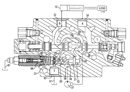
Fig. 1 is a cross-sectional view of an exemplary working valve section
including an exemplary three-way valve according to the invention, in which a
valve spool is in a position that enables full flow from the supply port to
the work
port, a pilot-operated pressure limiter valve is closed, and a pressure relief
port is
closed by the valve spool.
Fig. 2 is a close-up view of the exemplary three-way valve in Fig. 1.
Fig. 3 is a is a cross-sectional view of the working valve section in Fig. 1,
in the valve spool is in a flow regulating position, the pilot-operated
pressure
limiter valve is closed, and the pressure relief port is closed by the valve
spool.
Fig. 4 is a is a cross-sectional view of the working valve section in Fig. 1,
in which the pilot-operated pressure limiter valve is open, the valve spool is
in a
pressure reduced position, and the pressure relief port is closed by the valve
spool.
6
CA 2963197 2017-04-04
Fig. 5 is a is a cross-sectional view of the working valve section in Fig. 1,
in which the pilot-operated pressure limiter valve remains open, and the valve
spool is in a pressure relieving position for opening a flow path to the
pressure
relief port.
Fig. 6 is a schematic circuit diagram of the state of the valve section in
Fig. 3.
Fig. 7 is a schematic circuit diagram of the state of the valve section in
Fig. 5.
Fig. 8 is a graph illustrating work port flow (gpm) versus work port
pressure (psi) of an exemplary three-way pressure control valve according to
the
invention.
Detailed Description
The principles of the present invention have particular application to
sectional control valves used in hydraulically controlled machinery, for
example,
machinery used in stationary, mobile, aerospace, marine, and/or other
applications, and thus will be described below chiefly in this context. It is
also
understood that principles of this invention may be applicable to other
control
valves for various applications in which it is desirable to provide a three-
way
valve that enables pressure compensation for controlling flow and regulating
differences in fluid pressure sensed in a flow path of a valve body, that
enables
pressure reduction for effectively reducing fluid pressure in the flow path to
a
predetermined pressure level, and that enables pressure relief for relieving
fluid
pressure in the flow path when the fluid pressure in the flow path reaches or
exceeds the predetermined pressure level.
In the discussion above and to follow, the terms "upper", "lower", "top",
"bottom," "end," "inner," "outer," "left," "right," "above," "below," etc.
refer to a
three-way valve as shown in the cross-sectional view illustrated in Fig. 1.
This is
done realizing that these valves, such as when used on vehicles, can be
mounted on the top, bottom, or sides of other components, or can be inclined
with respect to the vehicle chassis, or can be provided in various other
positions.
Furthermore, the terms "upstream" and "downstream" refer to the arrangement
of elements along a flow path as fluid flows from a supply port, or source, to
a
7
CA 2963197 2017-04-04
work port or fluid operated device, realizing that hydraulic fluid may flow in
either
direction depending on the conditions experienced during operation.
Referring now in detail to the drawings, and initially to Fig. 1, an
exemplary three-way valve assembly 20 having a pressure control, flow
regulator, and pressure relief valve function is shown within a valve body 22.
In
the illustrated embodiment, the valve body 22 includes or is part of a working
valve section. The working valve section may be a unitary housing, or the
working valve section may be segmented. The working valve section may be
one of a plurality of individual sections that may be coupled together by
fasteners
in a known manner to provide a hydraulic valve assembly. The individual
working valve sections may be positioned adjacent to one another, such as in
abutting relationship, and those skilled in the art should recognize that any
number of working sections may be included in the assembly of valve sections.
The working valve sections of the valve section assembly may be the same as
one another, or may be different from one another.
The valve body 22 has a fluid flow path that fluidly connects various
passages and/or ports. The valve body 22 includes a longitudinally extending
main flow control valve through-passage 25, or main spool bore, for receiving
a
main control spool 26 having a longitudinal axis. A first end of the main
control
spool 26 is adapted to be connected to an external input command device, which
may be, for example, a lever 27, a handle or a joy stick that is manually
operated
by a human operator, a pilot signal, an electrical signal, solenoids, a
computer
program, a wireless signal, or any other suitable input that directly or
indirectly
causes operation of a valve. A second end of the main control spool 26 is
acted
upon by a biasing device 28, such as a spring, for returning the control spool
to a
neutral, closed position, all in a well-known manner.
A generally U-shaped chamber, or bridge passage 29, connects sides of
the main spool 26 on either side of a feed passage 40. The main spool 26 has a
pair of metering lands 30 which permit or restrict fluid communication between
the feed passage 40 and the bridge passage 29. Additionally, main spool 26 has
flow direction lands 31 which permit or restrict fluid communication between
the
bridge passage 29 and work ports 32 and 34. The work ports 32 and 34 extend
generally radially into the valve body 22 relative to the longitudinal axis of
the
8
CA 2963197 2017-04-04
main control spool 26 (vertically in the orientation shown in Fig. 1) and
fluidly
connect with passages that intersect the through-passage 25. Movement of the
main spool 26 either to the left or the right will permit selective
communication
between one of the work ports 32, 34 and the feed passage 40. When the main
spool 26 is shifted, the cylinder port that does not receive fluid from the
feed
passage 40 communicates with an appropriate exhaust port 33 or 35. It should
be noted that the control spool 26 in Fig. 1 is illustrated in a position
moved
longitudinally rightward away from its neutral position, to open a main valve
variable area orifice 36, which enables communication between the feed
passage 40 and the work port 32 so as to supply flow to a fluid operated
device
12, such as an actuator or motor, for example.
The valve body 22 also includes a supply port 38 (shown schematically),
or inlet passage, for receiving an inlet flow from a source 37, such as a pump
(shown schematically), for example a fixed displacement hydraulic pump. In the
illustrated embodiment, the supply port 38 is fluidly coupled to a supply
passage
39, which is connected to the feed passage 40. The through-passage 25, the
feed passage 40, and the bridge passage 29 provide a fluid flow path
(illustrated
in part by arrows in Fig. 3) extending between the supply port 38 and the work
ports 32 and 34. Generally, the upstream side of the flow path includes those
elements upstream of the main spool 26 and bridge passage 29, including the
source 37, supply port 38, supply passage 39, and feed passage 40; and the
downstream side of the flow path includes those elements downstream of the
bridge passage 29, including the work ports 32, 34, the fluid operated device
12,
a load sense passage 70, and other passages that will be described in further
detail below.
Referring to Figs. 1 and 2, the exemplary three-way valve 20 will be
described in further detail. The three-way valve 20 includes a valve member 50
that is movable in the valve body 22 and which is disposed in the fluid flow
path.
In the illustrated embodiment, the valve member 50 is a unitary valve member
which may provide a pressure compensating, pressure reducing, or pressure
relieving valve function. A pilot-operated pressure limiter valve 56, which is
shown toward an axial end of the valve member 50 in the illustrated
9
CA 2963197 2017-04-04
embodiment, may also be disposed in the fluid flow path to cooperate with the
valve member 50, as will be discussed in further detail below.
In the illustrated embodiment, the valve member 50 is configured as a
valve spool slidably moveable within a spool bore 21 in the valve body 22. The
valve spool 50 may include a metering edge that cooperates with a valve body
metering edge to meter fluid flow from the supply port 38, across the main
spool
variable orifice 36 and bridge passage 29, to the work port 32. The valve
spool
50 may include at least one land 60 having a radially outer sealing surface
configured to engage a radially interior sealing surface 62 of the valve body.
The
radially interior sealing surface 62 of the valve body may be considered a
valve
body land which may define at least a portion of the spool bore. The radially
interior sealing surface 62 of the valve body may be located between the
supply
passage 39 and the feed passage 40, and the radially outer sealing surface of
the land 60 is configured to cooperate with the radially interior sealing
surface 62
to meter fluid flow from the supply port 38 to the work port 32 based on a
position of the valve spool 50 in the spool bore.
The valve spool 50 also includes a valve surface 52 being movable with
the valve spool 50 and which is exposed to fluid pressure in the feed passage
40
upstream of the variable area orifice 36 of the main spool 26. The fluid
pressure
in the feed passage 40 acts on an opening radial surface area of the valve
surface 52 exposed to that fluid pressure, which exerts a force on the valve
spool 50 that urges the valve spool 50 toward a position in which the spool
land
60 engages the valve body land 62 to close off fluid flow from the supply
passage 39 to the feed passage 40 (as shown in Fig. 5, for example). In a
fully-
open position (as shown in Fig. 2, for example), an axial end of the valve
spool
50 may engage an axial end of the spool bore 21 to prevent further movement of
the valve spool 50. As the valve spool 50, including the spool land 60, moves
within the flow path between the various positions, the valve spool 50 may
regulate flow and control pressure of the fluid flowing from the source 37
through
the valve body 22.
As shown in the illustrated embodiment, the spool land 60 may also
include one or more axially extending metering notches, or metering slots, 64.
The metering notches 64 may be configured for enabling some leakage flow
CA 2963197 2017-04-04
from the supply passage 39 to the feed passage 40, even when the radially
outer
surface of the land 60 is engaged with the radially interior sealing surface
62 of
the valve body. As will be described in further detail below, when the pilot-
operated pressure limiter valve 56 is activated, the valve spool 50 may shift
toward a position that pinches down fluid flow to the feed passage 40 at the
metering slots 64. In this manner, the valve spool 50 becomes a pressure
reducing valve that is capable of maintaining working pressure at a pre-
determined level that may be set by the pilot-operated pressure limiter valve
56.
The valve body 22 also includes a load sense passage 70 that is located
downstream from the main spool variable area orifice 36 and the bridge passage
29. The load sense passage 70 is also in fluid communication with the work
port
32. The load sense passage 70 enables communication of a pressure feedback
signal that indicates the fluid pressure level at the work port 32 and/or the
work
side of the fluid operated device 12, which is communicated from the work port
32 to the valve member 50 via the load sense passage 70. In the illustrated
embodiment, the load sense passage 70 is separated from the supply passage
39 by a second sealing surface of the valve member 50, such as a second valve
spool land 66, that cooperates with an interior surface of the valve body 22,
such
as a valve body land 68, to sealingly engage and restrict fluid flow directly
from
the supply passage 39 to the load sense passage 70.
The load sense passage 70 may be fluidly connected to a load sense
chamber 72 located downstream from the load sense passage 70. In the
illustrated embodiment, a radially tubular wall 73 formed by the body of the
valve
member 50 defines at least a portion of the load sense chamber 72. The body of
the valve member 50 may have a through-passage that fluidly couples the load
sense passage 70 with the load sense chamber 72. The through-passage may
include an orifice 75 in the radially outer surface of the valve member 50
which
may be connected to one or more radial passages and/or axial passages.
The load sense chamber 72 is configured to transmit fluid pressure
communicated from the load sense passage 70, and the pressure in the load
sense chamber 72 exerts a force to the valve member 50 that tends to bias the
valve spool 50, including the spool land 60 and valve surface 52, toward a
position that enables flow from the supply passage 39 to the feed passage 40
11
CA 2963197 2017-04-04
(e.g., toward the right, as viewed in Fig. 1, for example). A biasing device
74,
such as a spring or the like, may be disposed in the load sense chamber 72, or
may be provided at an axial end of the valve member 50, so as to also provide
a
force that biases the valve spool 50 toward a position that enables flow from
the
supply passage 39 to the feed passage 40.
The fluid pressure in the load sense chamber 72 represents a
downstream fluid pressure acting on the valve spool 50 that urges the valve
member 50 in one direction (e.g., a position that enables flow from the supply
port to the work port), and which opposes and counteracts the upstream fluid
pressure in the feed passage 40 acting on the valve spool 50 that urges the
valve spool 50 in the opposite direction (e.g., a position that restricts flow
from
the supply port to the work port). In this manner, the valve spool 50 may be
exposed to fluid pressure at different locations in the fluid flow path and is
configured to sense and regulate fluid pressure differentials in the flow path
by
balancing forces on both sides of the valve member 50 to act as a pressure
compensator valve. Any one or more of the infinite positions in which the
valve
member acts as a pressure compensator valve for controlling flow and
regulating
fluid pressure differentials may be considered a first position of the valve
member, or a pressure compensating position.
Still referring to Figs. 1 and 2, the pilot-operated pressure limiter valve 56
is disposed in the fluid flow path between the load sense chamber 72 and a
pressure limiter valve passage 80, which may be in fluid communication with a
tank return line 81. The pilot-operated pressure limiter valve 56 is
configured to
regulate fluid pressure communicating with the load sense passage 70 and is
adapted to open the flow path between the load sense passage 70 and the
pressure limiter valve passage 80 when fluid pressure communicating with the
load sense passage 70 (such as via the load sense chamber 72) reaches or
exceeds a predetermined pressure level. For example, when the work port 32
pressure becomes greater than a predetermined pressure level set by the pilot-
operated pressure limiter valve 56, the pilot-operated pressure limiter valve
56
may be activated to open the flow path enabling fluid to be vented to the
reservoir or tank.
12
CA 2963197 2017-04-04
In response to this pilot flow, the fluid in the load sense chamber 72 may
experience a pressure drop as it flows across the orifice 75, whereupon the
valve spool 50 sensing this reduced pressure may then shift to the left to
close
off flow just enough to provide leakage across the metering notches 64 so as
to
satisfy the flow across the orifice 75 and through the pressure limiter
valvepassage 80 to maintain the desired pressure level at which the pilot-
operated pressure limiter valve 56 is set. Any one or more of the infinite
positions in which the valve member acts as a pressure reducer for effectively
reducing fluid pressure to a predetermined pressure level set by the pilot-
operated pressure limiter valve 56 may be considered a second position of the
valve member, or a pressure reducing position.
In the illustrated embodiment, the pilot-operated pressure limiter valve 56
includes a poppet valve 82 having a tapered body that engages a valve seat 84
when the pilot-operated pressure limiter valve 56 is in a closed position. The
pilot-operated pressure limiter valve 56 may also include a biasing device 86,
such as a spring or the like, which biases the poppet valve 82 toward the
closed
position for restricting fluid flow from the load sense chamber 72 to the
pressure
limiter valve passage 80. The biasing device 86 may be interposed between the
poppet valve 82 and an abutment within the pressure limiter valve passage 80.
In addition, pilot-operated the pressure limiter valve 56 may be adjustable to
set
the predetermined pressure level at which the pilot-operated pressure limiter
valve 56 is activated to open the fluid flow from the load sense chamber 72 to
the pressure limiter valve passage 80. For example, the force exerted by the
biasing device 86 may be adjusted in a well-known manner such that the force
from fluid pressure in the load sense chamber 72 must exceed the biasing force
before the pilot-operated pressure limiter valve 56 is activated.
The pressure limiter valve body 88 may be integral and unitary with the
valve body 22, or the pressure limiter valve body 88 may be separable and
attached to the valve body 22. In the illustrated embodiment, the pressure
limiter
valve body 88 is attached toward an axial end of the load sense chamber 72,
such that the pressure limiter valve passage 80 is coaxial with the spool bore
of
the valve spool 50. In other embodiments, the pilot-operated pressure limiter
valve 56 may be separate from the valve body 22 and fluidly coupled
13
CA 2963197 2017-04-04
downstream from the load sense chamber 72. For example, the load sense
chamber 72 may be bounded at its axial end with a port, outlet passage, and/or
a plug having a through-passage, which may be fluidly connected to the pilot-
operated pressure limiter valve 56 via fluid conduits or the like, for manual
remote control of the reduced/relief pressure setting. Or the pilot-operated
pressure limiter valve 56 may be replaced with an external electrohydraulic
pilot-
operated relief valve so the reducing/relieving pressure can be adjusted with
an
electronic input signal.
As shown in the exemplary embodiment in Figs. 1 and 2, the valve
member 50 also provides a pressure relief valve function by providing a valve
surface disposed in the fluid flow path between the load sense passage 70 and
a
pressure relief port 90 (which may be in fluid communication with a tank
return
line 91). In particular, the valve spool 50 may be configured to open the flow
path between the load sense passage 70 and the pressure relief port 90 when
the fluid pressure communicating with the load sense passage 70 exceeds the
predetermined pressure level provided by the pilot-operated pressure limiter
valve 56, thereby reducing the fluid pressure in the valve body 22 to an
acceptable level.
In the illustrated embodiment, the valve spool 50 includes a radially outer
sealing surface 93 configured to engage a radially interior sealing surface 94
of
the valve body. The radially outer sealing surface 93 of the valve spool may
be
configured as another valve spool land, which may define the radially outer
surface of the tubular wall 73 enclosing at least a portion of the load sense
chamber 72. The radially interior sealing surface 94 of the valve body may be
configured as another valve body land which may define at least a portion of
the
spool bore 21. In the illustrated embodiment, the radially interior sealing
surface
94 of the valve body is located between the load sense passage 70 and a
pressure relief passage 92, and the radially outer sealing surface 93 of the
valve
spool is configured to cooperate with the radially interior sealing surface 94
of
the valve body to permit or restrict fluid flow from the load sense passage 70
to
the pressure relief port 90 based on the position of the valve spool 50 in the
spool bore 21. For example, the valve spool 50 may abut the sealing surface 94
in one position to prevent flow between the load sense passage 70 and the
14
CA 2963197 2017-04-04
pressure relief passage 92. The spool 50 may include an undercut 54, or
groove, which extends axially along the spool bore axis. The undercut 54 may
be wider than the valve body land 94 to allow fluid flow from the load sense
passage 70 to the pressure relief passage 92 and to the pressure relief port
90
when the spool 50 is forced into a pressure relieving position, as will be
described in further detail below. Optionally, the radially outer sealing
surface 93
may also include axially extending notches or slots (similar to metering
notches
64), which may be configured for enabling flow from the load sense passage 70
to the pressure relief passage 92, which may enable improved stability during
operation of the device.
By providing the same valve member 50 in the fluid flow path to provide a
pressure compensation function, a pressure reducing function, and a pressure
relief function, the three-way valve 20 may effectively regulate fluid flow in
the
flow path of the valve body 22 while controlling and/or limiting fluid
pressure to
reduce damage or catastrophic failure under detrimental operating conditions.
More particularly, such a valve configuration may reduce the number of
associated components required to achieve the desired functions, and may
therefore reduce the complexity and overall cost of the valve assembly, among
other considerations. Furthermore, by providing a single pilot-operated
pressure
limiter valve 56, any adjustment that is made to the pressure level will
simultaneously move both the reduced and relief setting to the same new
pressure level.
Referring to Figs. 1-5, an exemplary operation of the three-way valve 20
and method of regulating fluid flow and controlling fluid pressure in the
valve
body 22 will be described in further detail. Generally, Fig. 1 illustrates a
state in
which flow is provided to the fluid operated device, but no higher load is
sensed
in another section, and the valve spool 50 is in a fully-open position to
allow flow
from the supply passage 39 to the feed passage 40; and in which the pilot-
operated pressure limiter valve 56 is closed and the valve spool 50 is
blocking
flow to the pressure relief port 90. Fig. 3 illustrates a state when the pump
pressure is much higher than the load on the fluid operated device or work
port
is sensed and the valve spool 50 is shifted to a partially open regulated
position
to regulate flow and control pressure. Fig. 4 illustrates a state when a
deadhead
CA 2963197 2017-04-04
condition occurs, for example, and an increase in fluid pressure in the valve
body
causes the pilot-operated pressure limiter valve 56 to activate and open the
flow
path to the pressure limiter valve passage 80, whereupon the valve spool 50
shifts to a position that allows just enough leakage flow past the metering
notches 64 to maintain a pressure level set by the pilot-operated pressure
limiter
valve 56. Fig. 5 illustrates a state when the load drives the fluid operated
device
12 in reverse, causing fluid to flow back through the work port 32, which
increases the fluid pressure to a level above the predetermined threshold
provided by the pilot-operated pressure limiter valve 56 and causes the valve
spool 50 to shift to a position where the valve spool 50 opens flow from the
load
sense passage 70 to the pressure relief port 90 to allow fluid venting to the
tank
or reservoir.
Generally during operation, the main control spool 26 may be moved
either leftward or rightward, as viewed in Fig. 1, from its neutral position
by the
input command device. Fig. 1 illustrates the control spool 26 shifted
rightward
from its neutral position and, as a result, a seat member of the biasing means
28
is forced a short distance away from a corresponding seating wall. When the
control spool 26 is shifted rightward in the manner as illustrated in Fig. 1,
hydraulic fluid enters the valve body 22 from the source 37 through the supply
port 38 and then flows into the supply passage 39. In the state shown in Fig.
1,
the valve spool 50 is fully open and fluid from the supply passage 39 flows
across the spool land 60 and the valve surface 52 into the feed passage 40 and
then into a center spool gallery of the through-passage 25.
A movable valve surface of the land 30 of spool 26 cooperates with an
adjacent stationary valve surface at the intersection of the through-passage
25
and center spool gallery to define the variable area orifice 36. Fluid flows
across
the variable area orifice 36 of the main spool 26 and then through the bridge
passage 29. The amount of fluid flowing from the center spool gallery of the
through-passage 25 to the bridge passage 29 varies depending upon the
position of the control spool 26 (which controls the area of the variable area
orifice 36) and the pressure of the fluid. As a result, a pressure drop occurs
as
the fluid flows from the feed passage 40, through the main control valve
variable
area orifice 36, and across the bridge passage 29. Thus, the fluid pressure in
16
CA 2963197 2017-04-04
the bridge passage 29 is typically less than the pressure in the feed passage
40
whenever there is fluid flow through the valve body 22.
The fluid flow (as illustrated by the arrows in Fig. 3, for example)
continues through the bridge passage 29 and is directed through a passage to
its associated work port 32 or 34. In the example shown in Fig. 3, the fluid
is
directed to the first work port 32. The fluid is then directed through its
associated
fluid conduit to its associated fluid operated device 12, such as an actuator.
At
the same time, fluid flow returning from the associated fluid operating device
is
directed into the second work port 34, through another passage and to the tank
return passage 35. The valve body working section works in a similar manner
when the spool is moved leftward from its neutral position for directing fluid
to the
second work port 34 and receiving return fluid in the first work port 32.
The fluid flow from the bridge passage 29 also continues to the load
sense passage 70, which establishes fluid communication with the work port 32.
In addition, fluid from the load sense passage 70 flows into the load sense
chamber 72 (via fluid orifice 75, for example) and also establishes
communication with the valve spool 50. This enables the feedback signal from
the work port 32 to communicate with the valve spool 50 to control pressure
and
regulate flow from the source 37 by moving the valve spool 50, including the
spool land 60 and valve surface 52, in the flow path between the supply
passage
39 and the feed passage 40.
When the main directional control spool 26 is shifted (as shown in FIG. 1,
for example), load pressure from the work port 32 is transmitted to the load
sense chamber 72, which in the illustrated embodiment is enclosed at least
partially by the valve spool 50 and contains a biasing member 74. As the main
spool 26 opens its metering area flow direction along land 30, the load
pressure
will be sensed in the load sense chamber 72. The load pressure acting in the
load sense chamber 72 will act against the end of the valve spool 50, causing
the valve spool metering land 60 to open away from the valve body land 62
(toward the right as viewed in Fig. 2). As the regulator land 60 opens, the
increasing flow to the main spool 26 will result in an increasing pressure
drop
across the main spool area opening at metering land 30. When the pressure
drop across the main spool 26 is equal to the force from the biasing member 74
17
CA 2963197 2017-04-04
(e.g., spring force) acting on the end of the valve spool at surface 52, then
the
valve spool 50 will modulate around its steady state position. This state of
equilibrium is created, in part, by the load pressure acting in the load sense
chamber 72 on one side of the valve spool 50, combined with the biasing
member 74 pre-load force. These combined forces cause the spool 50 and
metering land 60 to move to a position opening the flow path between the
supply
chamber 39 and the feed passage 40, and these combined forces are equally
opposed by regulated pressure in the feed passage 40 acting on the opening
radial surface area of the valve surface 52 exposed to that fluid pressure.
The opposing force caused by fluid pressure in the feed passage 40 is a
feedback force exerted on the valve surface 52 that is used to move the spool
50
and metering land 60 toward the second position as flow and the pressure drop
across the main spool 26 increase beyond the pre-load force of the bias member
74. The regulated/feedback pressure in the feed passage 40 is upstream of the
main spool variable area orifice 36 and bridge passage 29, making it a higher
pressure than the load pressure in the downstream load sense passage 70 due
to the pressure drop across the main spool 26. Therefore, the pressure drop
across the main spool 26 will equal the biasing member 74 pre-load force
acting
on the valve spool 50 since the load pressure in the load sense chamber 72 in
addition to the pre-load force will collectively equal the regulated pressure
in the
feed passage 40.
The spool metering land 60 will position itself within the flow path between
the supply passage 39 and the feed passage 40 to allow for the forces on
opposite sides of the valve spool 50 to become balanced, and the metering land
60 will automatically adjust its position within the feed passage 40 as the
main
spool metering area along metering land 30 changes and/or as the load pressure
or supply fluid pressure to the valve spool 50 itself changes. The feedback
surface 52 at the end of the spool 50 may be a part of the metering land 60
that
throttles the supply pressure from the supply passage 39 to the regulated
pressure in the feed passage 40. As the supply fluid pressure is throttled
down
to a lower "regulated" pressure, the fluid may flow around the metering land
60
of the spool 50, or through metering notches 64 (as shown in Fig. 3, for
example), to act directly on the exposed radial surface area of the valve
surface
18
CA 2963197 2017-04-04
52 at the end of the spool 50. The regulated pressure creates a feedback force
directly on this valve surface 52 of the spool 50 as the fluid flows to the
main
spool area opening at metering land 30. In this manner, the valve spool 50
operates as a pressure compensator valve that controls flow and regulates
fluid
pressure sensed in the flow path of the valve body.
Referring to Fig. 4, and discussed above, the valve member 50 may also
act as a maximum segment pressure limiter or reducing valve that cooperates
with the pilot-operated pressure limiter valve 56. For example, a deadhead
condition may occur when flow is directed toward the fluid operating device
and
movement of the device in response to the flow is somehow restricted or
stopped, which may cause an increase in the pressure level at the work port 32
and/or the valve body 22. When the work port 32 pressure communicated to the
load sense chamber 72 reaches or exceeds a predetermined or selected
pressure level that the biasing member 86 holding the check valve element
closed can support, the pilot-operated pressure limiter valve 56 may be
activated
(e.g., moved to an open position spaced from the valve seat) to open the flow
path from the load sense chamber 72 to a reservoir or tank, for example, via
the
pressure limiter valve passage 80.
The orifice 75 located in the communicating line between the main spool
load sensing passage 70 and the regulator spool load sensing chamber 72 may
provide for a pressure drop to be taken across the orifice 75 when the pilot-
operated pressure limiter valve 56 is cracked open to its preset value, which
lowers the fluid pressure in the load sense chamber 72. Once the pressure drop
across the orifice 75 in the load sense chamber 72 exceeds the pre-load force
of
the biasing member 74 on the valve spool 50, the valve spool 50 will shift to
close off flow to the main spool 26 and will create just enough leakage flow
between spool land 60 and valve body land 62, such as via the metering notches
64, to satisfy the flow across the orifice 72 and across the poppet 82 to
maintain
a pressure level at which the pilot limiter was set. This may be done to limit
or
reduce the maximum pressure in the valve body, or to maintain a fixed clamping
force on a cylinder, or a fixed torque on a rotary motor.
Referring to Fig. 5, and as discussed above, the valve member 50 may
also act as a pressure relief valve that acts to open or close the flow path
to a
19
CA 2963197 2017-04-04
pressure relief port 90 by providing a valve surface of the valve member 50
upstream from the pressure relief port 90. For example, the valve spool 50 may
be configured to open the flow path between the load sense passage 70 and the
pressure relief port 90 (via the pressure relief passage 92 extending across
the
spool 50) for venting pressurized fluid to tank, thereby preventing fluid
pressure
communicating with the load sense passage 70 from exceeding a pressure level
that is greater than the predetermined pressure level set by the pilot-
operated
limiter pressure limiter valve 56.
By way of a non-limiting example, as shown in Fig. 5, when a fluid
operated device 12 is moving against a load, or is deadheaded against a load,
and then suddenly the fluid operated device 12 is overcome by an increased
load such that the fluid may flow back through the work port 32 (as shown with
arrows), the pressure level in the valve body 22 may increase to a level
beyond
the pilot-operated pressure limiter valve 56. In the exemplary scenario, the
work
port 32 pressure communicated to the load sense chamber 72 via the load
sense passage 70 may exceed the predetermined or selected pressure level that
activates the pilot-operated pressure limiter valve 56, thereby opening the
flow
path to the pressure limiter valve passage 80 and causing a pressure drop in
the
load sense chamber 72 across the orifice 75, which lowers the fluid pressure
in
the load sense chamber 72, resulting in a decreased force acting on that end
of
spool 50, as discussed above.
Also in the exemplary scenario, the reversal of flow in the flow path of the
valve body 22 may increase the fluid pressure in the feed passage 40, which
will
exert an increased force on the valve surface area 52 which biases the valve
spool 50 toward a position in which the spool land 60 (and optionally metering
notches 64) may completely close flow between the supply passage 39 and the
feed passage 40. When the flow between the supply passage 39 and the feed
passage 40 is closed in this manner, the flow through the pilot-operated
pressure
limiter valve 56 may instead be satisfied by the backflow through the work
port
32 rather than from the source 37. The shift of the valve spool 50 to this
position
also causes the spool land having sealing surface 93 (or other pressure relief
valve surface) to move with the valve spool 50 to a position in which the flow
path from the load sense passage 70 to the pressure relief port 90 is opened
for
CA 2963197 2017-04-04
venting fluid to tank, thereby relieving pressure in the valve body 22. As
shown
in Fig. 5, for example, the valve spool 50 is shifted to a position in which
the
spool sealing surface 93 disengages from the valve body sealing surface 94
such that the undercut 54 straddles the valve body sealing surface 94 to allow
fluid flow from the load sense passage 70 to the pressure relief passage 92
and
to the pressure relief port 90. The orifice 75 may be disposed on the undercut
54 to enable flow from the load sense passage 70 to the load sense chamber 72
after the spool 50 is shifted to such a pressure relieving position.
In other words, after the pilot-operated pressure-limiter valve 56 is
activated and there is a pressure drop in the load sense chamber 72 across the
orifice 75, the valve spool 50 may move toward a position for opening the flow
path from the load sense passage 70 to the pressure relief port 90 when the
fluid
pressure in the feed passage 40 (which urges the valve spool to the left in
Fig. 5)
exceeds the combined forces from the reduced fluid pressure in the load sense
chamber 72 and the force from the biasing device 74 (which urges the valve
spool to the right in Fig. 5). Any one or more of the infinite positions in
which the
valve member acts as a pressure relief valve for relieving fluid pressure in
the
flow path when the fluid pressure exceeds the predetermined pressure level set
by the pilot-operated pressure limiter valve 56, may be considered a third
position of the valve member, or a pressure relieving position. As would be
understood by those skilled in the art, the three-way valve 20 may be adapted
to
provide such pressure relief at a prescribed pressure level above the
predetermined pressure level provided by the pilot-operated pressure limiter
valve 56 setting through suitable configuration of the associated components
or
other externally plumbed components.
Such an exemplary three-way valve as described herein may provide
pressure compensation for controlling flow and regulating differences in fluid
pressure sensed in a flow path of a valve body, may provide pressure reduction
for effectively limiting or reducing fluid pressure in the flow path to a
predetermined pressure level set by cooperating pilot-operated pressure
limiter
valve, and may provide pressure relief for relieving fluid pressure in the
flow path
when the fluid pressure in the flow path reaches or exceeds the predetermined
pressure level set by the pilot-operated pressure limiter valve, for example,
when
21
CA 2963197 2017-04-04
a deadhead condition occurs and then flow is inadvertently reversed in the
flow
path.
Turning now to Figs. 6 and 7, schematic diagrams of valve sections
constructed generally in accordance with the previous description are shown.
The reference numbers indicated in Figs. 6 and 7 are substantially the same as
the reference numbers used in Figs. 1-5, and consequently the same reference
numerals but indexed by 100 are used to denote structures corresponding to
substantially the same or similar structures in the three-way valve 20. As
such,
the foregoing description of the three-way valve 20 is equally applicable to
the
three-way valve 120. Fig. 6 illustrates a state when a load on the fluid
operated
12 device or work port is sensed and the valve spool 50 is shifted to regulate
flow and control pressure, which corresponds with Fig. 3 above. Fig. 7
illustrates
a state when the valve spool 50 is shifted to the pressure relieving position
where the valve spool 50 opens flow to the pressure relief port 90 to allow
fluid
venting to the tank or reservoir, which corresponds with Fig. 5.
Referring now to Fig. 8, a graph illustrating work port flow (gpm) versus
work port pressure (psi) of a three-way valve according to the previous
description during experimental operation is shown. In the illustrated
example,
the pump provides 30 GPM of flow to the valve body and the work port is
provided with about 20 GPM of flow up to a fluid pressure of about 3300 psi,
which is indicated at reference number 200. At this point indicated by
reference
number 200, the pilot-operated pressure limiter valve activates and the three-
way valve spool is shifted to reduced flow to the work port, which is
indicated at
reference number 205 as "reducing," and which corresponds generally with the
state in Fig. 4. The predetermined pressure level threshold set by the pilot-
operated pressure limiter valve in this example is about 3700 psi, as
indicated at
reference number 210, where work port flow is at or near zero. As the flow in
the
work port is reversed, as shown with negative work port flow on the y-axis and
indicated at reference number 215 and corresponding generally with the state
in
Fig. 5, the three-way valve spool is shifted to close flow from supply to the
work
port, and to open flow to the pressure relief port. In this region indicated
by
reference number 215, the pressure in the valve body is being relieved across
the three-way valve spool and vented to the tank. The three-way valve spool is
22
CA 2963197 2017-04-04
shifted to a position in which the pressure relief flow path is open at the
point
indicated by reference numeral 220. Further relief flow would result if the
load
pressure was higher. In this case, the three-way valve spool would shift open
further or the pressure drop across the fully opened three-way valve spool
would
increase.
Although the invention has been shown and described with respect to a
certain embodiment or embodiments, it is obvious that equivalent alterations
and
modifications will occur to others skilled in the art upon the reading and
understanding of this specification and the annexed drawings. For example,
although the three-way valve was shown in a pre-compensated configuration,
the three-way valve could also be used in a post-compensated configuration, as
would be understood by those skilled in the art. In particular regard to the
various functions performed by the above described elements (components,
assemblies, devices, compositions, etc.), the terms (including a reference to
a
"means") used to describe such elements are intended to correspond, unless
otherwise indicated, to any element which performs the specified function of
the
described element (i.e., that is functionally equivalent), even though not
structurally equivalent to the disclosed structure which performs the function
in
the herein illustrated exemplary embodiment or embodiments of the invention.
In addition, while a particular feature of the invention may have been
described
above with respect to only one or more of several illustrated embodiments,
such
feature may be combined with one or more other features of the other
embodiments, as may be desired and advantageous for any given or particular
application.
23