Note: Descriptions are shown in the official language in which they were submitted.
ELECTRIC FRYER
10
FIELD OF THE INVENTION
The invention is related to the "deep fat" frying of food. More specifically,
the invention is
related to appliances and methods for such frying. In particular, the
invention provides an
improved means for maintaining clean and fresh cooking oil or "fat" in such
appliances.
BACKGROUND OF THE INVENTION
Appliances for deep fat frying are common and well known. Such appliances
typically include a
tank for holding the oil in which the food is to be fried (the "fat"), means
for heating that oil to a
temperature sufficiently high to fry the food when the food is immersed
therein, and a basket or
other form of food holding device for manipulating the food, such as immersing
it into the oil to
fry and removing it from the oil when frying is completed.
A common problem with such appliances is that the oil supply contained therein
will quickly
become contaminated with bits of food during frying, will become foul tasting
and malodorous
by the combination of such bits of food remaining therein and by prolonged
periods at high
temperatures, and by remaining non-refrigerated in the appliance for long
periods between uses
and thereby spoiling. So there is a need for a fryer that allows for the
cleansing and refrigerated
storage of the oil between uses.
1
Date Recue/Date Received 2020-07-17
Another problem common to deep fryers is that the oil is often used to cook
foods that may
cause allergic reactions in some persons, such as fish. So when if the fryer
allows for such
storage and reuse, caution needs to be used to avoid such reuse for those
persons. So there is a
need a fryer that allows for the storage and reuse of distinct vessels of such
used oils; such as
allergic and non-allergic.
US Patents 6666131 and 7314001, co-invented and co-owned by SEB S.A., teach a
deep fryer
having a removable emptying vessel into which used oil may be drained by a
control mechanism
that activates a drain valve of the cooking vessel. However, the control
mechanism for
activating the drain valve is disadvantageously mounted on the emptying vessel
and so, if more
than one vessel is used, such as described above, the mechanism must be
repeated for each
vessel, causing unneeded expense and complication. Further, because the
mechanism is the
most delicate part of the vessel and is exposed on the vessel when it is
removed from the fryer, it
is prone to damage.
In its later T-Fal FR8000 fryer, SEB S.A. apparently attempts to rectify that
deficiency by
moving most of the control mechanism to the fryer, but leaves a critical
portion of the
mechanism in a precarious valve-actuating member that extends from and is part
of the
emptying vessel. Additionally, because the mechanism is shared by two major
and separable
components whose relative disposition is difficult to precisely control, the
reliability of the
valve actuation is compromised. It is found that the valve actuation mechanism
does not
properly operate unless the emptying vessel is carefully moved into "just the
right position".
There is a need for a fryer that employs one or more emptying and storing
vessels in which the
cost, complexity, and vulnerability of the vessel is minimized, and such is an
object of the
present invention. There is the need for such a fryer in which the valve
operating mechanism is
solely contained within the fryer and not reliant on the precise positioning
of the vessel, and
such is an object of the present invention. There is the need for such a fryer
in which, when used
with multiple vessels, redundant components are minimized, and such is an
object of the present
2
Date Recue/Date Received 2020-07-17
invention. Further advantages and objects of the present invention exist,
which will be
appreciated upon review of the included disclosure.
SUMMARY OF THE INVENTION
The invention may be embodied in or practiced using a deep fat frying
appliance which includes
means for filtering contaminants from the oil after cooking and means for
transferring that
filtered oil into a storage device which may be removed from the appliance and
refrigerated, to
thereby keep the oil fresh and reusable for a longer time and for more
frequent re-uses.
The invention may be embodied in or practiced using an appliance for deep
frying foodstuffs
having a housing with a frying pot disposed therein for containing cooking oil
or fat and having
a normally-closed draining valve disposed at a bottom thereof. An oil
receiving tank may be
removably receivable within the housing below the frying pot, may have an oil
receiving hole
positionable below the draining valve such that when the draining valve is
opened, the cooking
oil or fat may flow from the frying pot into the oil receiving tank.
The appliance may have an actuation mechanism disposed entirely on the housing
and having a
first condition wherein the activation mechanism allows removal and
replacement of the oil
receiving tank relative to the housing, a second condition wherein the
activation mechanism
prevents removal and replacement of the oil receiving tank relative to the
housing while not
opening the draining valve, and a third condition wherein the activation
mechanism prevents
removal and replacement of the oil receiving tank relative to the housing
while opening the
draining valve.
The oil receiving tank may include a seal movable to either seal or unseal the
oil receiving hole
and engagable by the housing such that the oil receiving hole is sealed when
the tank is removed
from the housing and unsealed when the tank is received within the housing.
The seal may be
slidable co-directionally with the reception and removal of the oil receiving
tank relative to the
housing such that engagement of the seal with the housing causes the seal to
slide between an
unsealing and a sealing position.
3
Date Recue/Date Received 2020-07-17
The actuation mechanism may include a rotor having a user-operable knob
portion and a valve
actuator portion, wherein rotation of the knob portion between the second and
third conditions
causes the valve actuation portion to open and close the valve, respectively.
The rotor may have
a cam and the actuation mechanism may include a movable link, and rotation of
the knob
portion from the second condition to the third condition may cause the link to
open the valve and
rotation the knob portion from the third condition to the second condition may
cause the link to
close the valve. The link may be a spring-biased rocker pivotable in a "see-
saw" motion by
engagement with the cam such that as the cam forces a proximal end of the
rocker downwardly,
a distal end of the rocker moves upwardly to force open the valve.
The rotor may include a blocking member, and rotation of the rotor from the
first condition to
either of the second or third conditions may cause the blocking member to
prevent removal and
replacement of the oil receiving tank relative to the housing.
The appliance may have a filter for removing particulate matter from the
cooking oil or fat as the
cooking oil or fat flows from the frying pot into the oil receiving tank. The
filter may be
disposed within the frying pot. The draining valve may include the filter. The
filter may be
removable from the appliance for cleaning or replacement.
The invention may alternatively be embodied in or practiced using an appliance
for deep frying
foodstuffs with a housing, a frying pot disposed within the housing for
containing cooking oil or
fat and having a normally-closed draining valve disposed at a bottom thereof,
and a heating
control removably engagable with the housing.
The heating control may have a heating element disposed within the frying pot
when the heating
control engages the housing to heat the cooking oil or fat, and a control for
selectively
energizing the heating element.
4
Date Recue/Date Received 2020-07-17
An oil receiving tank may be removably receivable within the housing below the
frying pot,
having an oil receiving hole positionable below the draining valve such that
when the valve is
opened, oil may flow from the frying pot into the oil receiving tank.
The appliance may have an actuation mechanism disposed entirely on the housing
and with a
first condition wherein the activation mechanism allows removal and
replacement of the oil
receiving tank relative to the housing, a second condition wherein the
activation mechanism
prevents removal and replacement of the oil receiving tank relative to the
housing while not
opening the valve, and a third condition wherein the activation mechanism
prevents removal
and replacement of the oil receiving tank relative to the housing while
opening the valve.
The oil receiving tank may include a seal movable co-directionally with the
reception and
removal of the oil receiving tank relative to the housing to either seal or
unseal the oil receiving
hole and engagable by the housing such that the oil receiving hole is sealed
when the tank is
removed from the housing and unsealed when the tank is received within the
housing. The
actuation mechanism may include a rotor having a user-operable knob portion
and a valve
actuator portion, and rotation of the rotor between the second and third
conditions may cause the
valve actuation portion to open and close the valve, respectively. The rotor
may have a cam.
The actuation mechanism may include a spring-biased rocker, and rotation of
the rotor from the
second condition to the third condition may cause the cam to force a proximal
end of the rocker
downwardly, a may cause a distal end of the rocker to move upwardly to force
open the valve.
The rotor may also include a blocking member, and rotation of the rotor from
the first condition
to either of the second or third conditions may cause the blocking member to
prevent removal
and replacement of the oil receiving tank relative to the housing.
The draining valve may include a filter for removing particulate matter from
the cooking oil or
fat as the cooking oil or fat flows from the frying pot into the oil receiving
tank.
5
Date Recue/Date Received 2020-07-17
Further features and aspects of the invention are disclosed with more
specificity in the Detailed
Description and Drawings provided herein and showing exemplary embodiments of
the
invention.
BRIEF DESCRIPTION OF THE DRAWINGS
An exemplary embodiment of a deep fat fryer in accordance with or useful in
practicing the
invention are shown in the accompanying Drawings, of which:
Figure 1 is an exploded view of a deep fat fryer;
Figure 2 is a perspective view of the fryer of Figure 1;
Figure 3 is a full side cross sectional view through the fryer of Figure 1;
Figure 4 is a partial perspective view of the fryer of Figure 1 with is oil
storage tank
being removed;
Figure 5 is an exploded partial perspective view of the oil storage tank of
the fryer of
Figure 1;
Figure 6A is a perspective view of the assembled oil storage tank of Figure 5
in its sealed
configuration;
Figure 6B is a partial top view of the sealing mechanism of the oil storage
tank of Figure
6A in its sealed configuration;
Figure 6C is a partial cross sectional view of the sealing mechanism of Figure
6B in its
sealed configuration;
Figure 7A is a partial perspective view of the assembled oil storage tank of
Figure 5 in its
filtered oil receiving configuration;
Figure 7B is a partial top view of the sealing mechanism of the oil storage
tank of Figure
7A in its filtered oil receiving configuration;
Figure 7C is a partial cross sectional view of the sealing mechanism of Figure
7B in its
filtered oil receiving configuration;
Figure 8A is a partial cross sectional view through the seal activation system
of the fryer
of Figure 1 in its locked configuration;
Figure 8B is a partial cross sectional view through the seal activation system
of the fryer
6
Date Recue/Date Received 2020-07-17
of Figure 1 in its oil filtering configuration;
Figure 8C is a partial cross sectional view through the seal activation system
of the fryer
of Figure 1 in its unlocked configuration;
Figure 9A is a partial front view of the fryer of Figure 1 in its locked
configuration;
Figure 9B is a partial front view of the fryer of Figure 1 in its oil
filtering configuration;
Figure 9C is a partial front view of the fryer of Figure 1 in its unlocked
configuration;
Figure 10 is a perspective view of the filter/valve assembly of the fryer of
Figure 1;
Figure 11 is an exploded view of the filter/valve assembly of the fryer of
Figure 1;
Figure 12 is a side view of the seal activating mechanism of the fryer of
Figure 1;
Figure 13 is a perspective view of the seal activating mechanism of Figure 12;
Figure 14 is a cross-sectional of the sliding seal of the fryer of Figure 1
taken at Line
14-14 of Figure 7B; and
Figure 15 is a partial exploded internal view of the fryer of Figure 1.
DETAILED DESCRIPTION OF THE PREFERRED EMBODIMENTS
Referring to Figures 1 through 15, the invention may be embodied in or
practiced using the
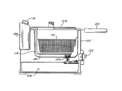
depicted electrical deep frying appliance 100. The deep fryer includes a main
housing 102, a
heating control 104, a lid 106, a filtered oil tank 108, and food baskets. The
food baskets include
large basket 110 and two small baskets 112. The main housing includes a frying
pot 114 that is
intended to receive cooking oil. The heating control includes an electrical
control box 116 and
a tubular electric heating element 118. The control box includes a power cord
(not shown) for
connection to electrical power, and controls for programming and operating the
heating
element, cooking temperature, and timing.
The lid and heating control are removable from the main housing to simplify
cleaning of these
components individually and for other advantageous reasons. With the lid
removed and the
heating control properly engaged into the main housing, the heating element is
disposed near the
bottom of the frying pot. Cooking oil may then be poured into the cooking pot
to a level high
within the pot, as shown in Figure 3. The heating element may then heat the
cooking oil in the
7
Date Recue/Date Received 2020-07-17
pot to a desired temperature according to the user's selection. A
thermostatically¨controlled
display on the control box may indicate when the oil is at the proper frying
temperature.
The large basket, or one or both of the small baskets may then be loaded with
food to be fried
.. and lowered into the pot such that the food is immersed below the top
surface of the heated
cooking oil and is fried there-within. Figure 2 shows the handles of small
baskets in broken lines
to demonstrate where they would be positioned when used.
The lid may or may not be replaced over the frying pot during frying. The
basket's handle 120
rests on the upper perimeter of the housing to position and retain the food
properly within the
oil, and extends from the appliance for safety and convenience when
manipulating the basket. A
timer in the heating control may indicate, via the display, when the food has
been sufficiently
fried. The baskets are also configured to engage the housing in a position
directly above the
cooking pot, such as after frying is complete. The baskets are, of course,
perforated to allow the
.. oil to circulate through the basket and food during frying, and to allow
the oil to drain from the
basket back into the cooking pot when resting in the above position after
frying. After the food
has been served, the empty basket, lid, and heating control may be taken to
the sink and washed.
The heating element is displaced from the bottom of the cooking pot during
frying sufficiently
to allow circulation of the oil as it is heated and to allow space for food
crumbs and such to
collect below as they inadvertently fall from frying food, so that they are
not in contact with the
heating element. Such contact will not only insulate the heating element from
the oil, but will
also promote burning and undesirable oil qualities. Cooking oil is relatively
expensive, but may
be re-used many times if not overheated, if kept clean, and if refrigerated
between uses. But
these crumbs and such are undesirable pollutants that can taint and otherwise
shorten the life of
the cooking oil. They impart bad flavors, colors, and odors into the oil, and
they spoil much
faster than the oil, even when refrigerated.
In typical prior art fryers, a user intent on saving the used oil for re-use
would typically allow the
.. oil to cool in the cooking post, then lift the appliance and pour the used
oil through a funnel into
8
Date Recue/Date Received 2020-07-17
a separate container for placement into a refrigerator. But of course, such
pouring from a heavy
appliance was prone to spillage and messy waste. The oil pouring from the
appliance would
initially be the clear oil at the top of the pot, but would eventually get
cloudier and include more
crumbs as it was poured. While the user might try to terminate the pouring as
the crumbs begin
to flow into the container, it was impossible to prevent the flow of some of
the crumbs, and the
crumbs remaining in the pot would include a significant amount of useful oil
that would then be
wasted.
To overcome this deficiency, the bottom of frying pot 114 is equipped with a
novel filtering
drain system that communicates directly and selectively with the removable
filtered oil tank
108, as shown in Figures 3 thru 15.
The operation of the filtering drain system is depicted in Figures 8A through
9C, and the related
components are shown in Figures 5 through 7C and 10 through 15. The components
of the
system include filter/valve assembly 130, actuation rotor 132, sliding seal
134, and
spring-biased rocker 136. The filter/valve assembly includes filtering cap 138
and
normally-closed spring-biased valve 140. Actuation rotor 132 and spring-biased
rocker 136
together form a valve actuation mechanism. The portion of the actuation rotor
outside of
housing is a knob portion for access by the user, and the portion within the
housing is a valve
actuation portion for engaging and controlling the filter/valve assembly and
spring-biased valve.
The filter valve assembly is affixed through a drain hole in the bottom of the
flying pot. Porous
filtering cap 138 is removable for cleaning or replacement. As shown, this cap
is made of
perforated formed stainless steel sheet, but it might otherwise be made of
formed screen or any
equivalent construction, provided that the openings there-through are large
enough to allow the
passing of oil but small enough to prevent the passing of most food particles.
It is found that
openings of approximately 1.5 to 2 MM perform adequately. The valve is biased
closed by
compression spring 146 so that valve stem 148 is normally forced downwardly to
seal the drain
hole.
9
Date Recue/Date Received 2020-07-17
Rocker 136 is pivotally affixed to support 149 of the main housing at hinge
pin 150 and biased
by compression spring 152 so that its valve-actuating post 154 at the rocker's
distal end is
normally positioned down below and not in contact with the valve stem (When
used herein, the
term "proximal" shall be meant to mean towards a user positioned at the front
of the appliance,
and the term "distal" shall be meant to mean the opposite). This leaves valve
140 in its normally
closed condition. The proximal end of the rocker is selectively engagable by
cam 155 of the
actuation rotor so that when the rotor is rotated the cam causes the rocker to
pivot in a "see-saw"
motion against the bias of spring 152, such that the valve-actuating post
moves upward against
the valve pin, forcing the valve open. Reverse rotation of the rotor allows
spring 152 to force the
rocker's valve actuating post back down, thereby allowing spring 146 to force
the valve closed.
Sliding seal 134 is slidingly affixed to filtered oil tank 108 and normally
biased by two
compression springs 160 so that the sliding seal covers over and seals
filtered oil hole 162 of the
tank. When the tank is pushed into the main housing, the sliding seal engages
tab 164 of support
149 to force the sliding seal towards the proximal end of the tank, thereby
aligning the sliding
seal's funnel 166 with the filtered oil hole as the filtered oil hole becomes
aligned under valve
140. Pulling the tank back out of the housing, when allowed to do so by the
position of the
actuating rotor (as later explained) allows the sliding seal to move back
towards the distal end of
the tank, under the influence of springs 160, to cover over and re-seal the
filtered oil hole.
Actuation rotor 132 serves two functions;
1) it locks filtered oil tank 108 into main housing 102 to prevent its removal
except under
the proper circumstances, and
2) it actuates rocker 136 to actuate valve 140 under the proper circumstances.
The filtered oil tank may be may slid into or from the housing when the
actuation rotor is in its
"Unlock" position, as demonstrated in Figures 4, 8C, and 9C. When the tank is
properly
positioned within the housing, as shown in Figures 2 and 3, the rotor may be
rotted to its "Lock"
position, as shown in Figures 8A and 9A, so that the rotor's blocking tab 167
rotates to block
removal of the tank. In this "Lock" position the valve is not forced open by
the rotor's cam 155
Date Recue/Date Received 2020-07-17
(best appreciated by viewing Figure 8A), so oil 168 is retained in frying pot
114 and heating
control 104 may be operated to perform frying, as described above.
After frying is complete, actuation rotor 132 may be rotated to its "Filter
Oil" position, whereby
cam 155 engages the proximal end of rocker 136 to cause the opening of valve
140, as described
above, to thereby allow the used "dirty" oil 158 to flow from pot 114, through
filter cap 138
(whereby it is converted to "clean oil" suitable for re-use), through opened
valve 140, through
funnel 166 and filtered oil hole 162, and into filtered oil tank 108. Note
that blocking tab 167
continues to prevent removal of the tank during the "Filter Oil" arrangement.
Actuation rotor 132 may then be rotated to its "Unlock" position, as shown in
Figures 8C and
9C, whereby blocking tab 167 is no longer blocking removal of the tank, and
valve 140 is
allowed to re-close, and the filtered oil tank, now filled with filtered
"clean" oil, may be
removed from housing 102 and stored in a refrigerator.
The filtered oil tank is also equipped with means to neatly pour the filtered
oil back into the
frying pot prior to the next frying event. Plug 170 normally seals a pouring
hole (not shown) in a
distal corner of the tank. When the plug is removed, the tank may be
positioned over the frying
pot and, because the pouring hole is adjacent a corner of the tank, oil may be
poured from the
tank without spillage or the need for a funnel.
While the heating element shown is an immersible electrical heating tube, and
the heating
control is removable from the housing, other common means for controlling and
heating may
alternatively be employed without departing from the invention. For instance,
the invention
could be equivalently practiced in a frying appliance having a heating element
disposed under
the frying pot and above the filtered oil tank. Or the heating of the oil
could be accomplished by
a gas-burning flame under the frying pot and above the filtered oil tank.
Additionally, the
controls could be equivalently arranged as a permanently affixed portion of
the housing without
departing from the scope of the invention.
11
Date Recue/Date Received 2020-07-17
Further, the rocker operation could be flipped over and the valve
configuration could be such
that the valve is opened when the valve stem is pulled down rather than pushed
up, and the
rocker could engage the valve stem and be caused by the cam to pull the valve
stem down when
the rotor is turned to the "Filter Oil" position.
So while the invention has been shown and described with reference to a
specific exemplary
embodiment, it should be understood by those skilled in the art that various
changes in form and
detail may be made without departing from the spirit and scope of the
invention, and that the
invention should therefore only be limited according to the following claims,
including the
broadest interpretation to which they are entitled.
12
Date Recue/Date Received 2020-07-17