Note: Descriptions are shown in the official language in which they were submitted.
SYSTEMS AND METHODS FOR SYNTHESIS OF NITRIC OXIDE
CROSS-REFERENCES TO RELATED APPLICATIONS
[0001] The present application is based on, and claims priority to
United States Provisional Patent Application
No. 62/065,825, filed October 20, 2014, and entitled "Producing Nitric Oxide
for
Inhalation by Electric Discharge in Air," and United States Provisional Patent
Application No. 62/077,806, filed November 10, 2014, and entitled "Synthesis
of Nitric
Oxide."
STATEMENT REGARDING FEDERALLY SPONSORED RESEARCH
[0002] Not Applicable.
BACKGROUND
[0003] The disclosure relates generally to the electrical plasma synthesis
of nitric
oxide (NO) from gases and, more specifically, to systems and methods for
producing
safe NO to be used in medical applications.
[0004] NO is a crucial mediator of many biological systems, and is known to
control the level of systemic and pulmonary artery blood pressure, help the
immune
system kill invading parasites that enter cells, inhibit the division of
cancer calls,
transmit signals between brain cells, and contribute to the death of brain
cells that
debilitates people with strokes or heart attacks, among other things. NO
mediates the
relaxation of smooth muscle present, for example, in the walls of blood
vessels,
bronchi, the gastrointestinal tract, and urogential tract. Administration of
NO gas to
the lung by inhalation has been shown to produce localized smooth muscle
relaxation
within the lung's blood vessels and is widely used to treat pulmonary
hypertension,
pneumonia, hypoxemic respiratory failure of a newborn, etc. without producing
systemic side effects.
-1-
Date Recue/Date Received 2022-03-04
CA 02963874 2017-04-05
WO 2016/064863 PCT/US2015/056443
[0005] Inhaling NO can immediately produce potent and selective pulmonary
vasodilation that improves the matching of ventilation with perfusion, thereby
increasing an injured lung's oxygen transport efficiency, and breathing NO can
raise
the arterial oxygen tension. Breathing NO produces the rapid onset of
pulmonary
vasodilator action occurring within seconds of commencing breathing with the
absence of systemic vasodilatation. Once inhaled, NO diffuses through the
pulmonary
vasculature into the bloodstream, where it is rapidly inactivated by
combination with
hemoglobin (the NO dioxygenation reaction). Therefore, the vasodilatory
effects of
inhaled NO are limited to these pulmonary therapeutic advantages in the
treatment
of acute and chronic pulmonary hypertension. Inhaled NO can also be used to
prevent
ischemia reperfusion injury after percutaneous coronary intervention in adults
with
heart attacks. Furthermore, inhaled NO can produce systemic anti-inflammatory
and
anti-platelet effects by increasing the levels of circulating NO
biometabolites and by
other mechanisms, such as the oxidation of circulating ferrous hemoglobin in
the
plasma. Finally, NO has known anti-microbial activity.
BRIEF SUMMARY
[0006] The present disclosure provides systems and methods for producing
nitric
oxide (NO) to be used in medical applications. Specifically, systems and
methods are
provided for a NO generator that is capable of generating a desired
concentration of
pure and safe NO to be provided to a respiratory system for inhalation by a
patient.
[0007] In one aspect, the present disclosure provides an apparatus for
generating
nitric oxide including one or more pairs of electrodes, a filter arranged
downstream of
the electrodes, and a scavenger arranged downstream of the electrodes. The
apparatus further includes one or more sensors configured to measure at least
one of
a flowrate of gas, an oxygen concentration upstream of the electrodes, a
nitric oxide
concentration downstream of the scavenger, and a nitrogen dioxide
concentration
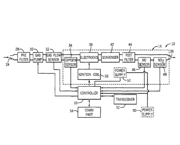
downstream of the scavenger, and a controller in communication with the
electrodes
and the one or more sensors and configured to supply an electrical signal to
the
electrodes that controls timing and sparking characteristics of the
electrodes. The
-2-
CA 02963874 2017-04-05
WO 2016/064863 PCT/US2015/056443
sparking characteristics of the electrodes determine a concentration of nitric
oxide
generated by the electrodes.
[0008] in some embodiments, the electrodes comprise at least one of
tungsten
carbide, carbon, nickel, iridium, titanium, rhenium, and platinum
[0009] In some embodiments, the electrodes comprise iridium.
[0010] In some embodiments, the scavenger is fabriced from calcium
hydroxide.
[0011] In some embodiments, the one or more sensors include an airway
flowmeter
arranged downstream of the electrodes, an oxygen sensor arranged upstream of
the
electrodes, a nitric oxide sensor arranged downstream of the scavenger, and a
nitrogen dioxide sensor arranged downstream of the scavenger.
[0012] In some embodiments, an ignition coil is in communication with the
controller and the electrodes.
[0013] In some embodiments, the controller is further configured to
instruct the
ignition coil to supply stored electrical energy to the electrodes.
[0014] In some embodiments, the electrical signal supplied to the
electrodes
controls at least one of a number of electrode spark groups per second, a
number of
individual electrode sparks per spark group, a time between individual
electrode
sparks, and a pulse duration.
[0015] In some embodiments, the controller is further configured to vary at
least
one of the number of electrode spark groups per second, the number of
individual
electrode sparks per spark group, the time between individual electrode
sparks, and
the pulse duration in response to feedback from the one or more sensors.
[0016] In some embodiments, the apparatus further comprises a gas pump
arranged upstream of the electrodes.
[0017] In some embodiments, the one or more sensors provide an indication
of
inspiration.
[0018] In some embodiments, the controller is further configured to supply
the
electrical signal to the electrodes in response to detecting inspiration.
-3-
CA 02963874 2017-04-05
WO 2016/064863 PCT/US2015/056443
[0019] In some embodiments, the filter is configured to filter particles
flowing
downstream of the electrodes with a diameter greater than approximately 0.22
micrometers.
[0020] In another aspect, present disclosure provides an apparatus for
generating
nitric oxide to be integrated into a respiratory system having a breathing
apparatus,
an inspiratory line, and an airway flowmeter arranged on the inspiratory line.
The
apparatus includes one or more pairs of electrodes in gaseous communication
with
the inspiratory line, a filter arranged downstream of the electrodes, and a
scavenger
arranged downstream of the electrodes. The apparatus further includes one or
more
sensors configured to measure at least one of an oxygen concentration upstream
of
the electrodes, a barometric pressure, a nitric oxide concentration downstream
of the
scavenger, and a nitrogen dioxide concentration downstream of the scavenger,
and a
controller in communication with the electrodes, the one or more sensors, and
the
airway flowmeter, and configured to supply an electrical signal to the
electrodes that
controls timing and sparking characteristics of the electrodes. The sparking
characteristics of the electrodes determine a concentration of nitric oxide
generated
by the electrodes.
[0021] In some embodiments, the electrodes are arranged between an inlet
and an
outlet, the outlet is coupled to the inspiratory line.
[0022] In some embodiments, the electrodes are at least partially
integrated into
the inspiratory line.
[0023] In some embodiments, the filter is arranged on the inspiratroy line.
[0024] In some embodiments, the scavenger is arranged on the inspiratory
line.
[0025] In some embodiments, the electrodes comprise at least one of
tungsten
carbide, carbon, nickel, iridium, titanium, rhenium, and platnium.
[0026] In some embodiments, the electrodes comprise iridium.
[0027] In some embodiments, the scavenger is fabricated from calcium
hydroxide.
[0028] In some embodiments, the one or more sensors include an oxygen
sensor
arranged upstream of the electrodes, a nitric oxide sensor arranged downstream
of
the scavenger, and a nitrogen dioxide sensor arranged downstream of the
scavenger.
-4-
CA 02963874 2017-04-05
WO 2016/064863 PCT/US2015/056443
[0029] In some embodiments, an ignition coil is in communication with the
controller and the electrodes.
[0030] In some embodiments, the controller is further configured to
instruct the
ignition coil to supply stored electrical energy to the electrodes.
[0031] In some embodiments, the electrical signal supplied to the
electrodes
controls at least one of a number of electrode spark groups per second, a
number of
individual electrode sparks per spark group, a time between individual
electrode
sparks, and a pulse duration.
[0032] In some embodiments, the controller is further configured to vary at
least
one of the number of electrode spark groups per second, the number of
individual
electrode sparks per spark group, the time between individual electrode
sparks, and
the pulse duration in response to feedback from the one or more sensors.
[0033] In some embodiments, the apparatus further comprises a gas pump
arranged upstream of the electrodes.
[0034] In some embodiments, the airway flowmeter provides an indication of
inspiration.
[0035] In some embodiments, the controller is further configured to supply
the
electrical signal to the electrodes in response to detecting inspiration.
[0036] In some embodiments, the filter is configured to filter particles
flowing
downstream of the electrodes with a diameter greater than approximately 0.22
micrometers.
[0037] In some embodiments, the breathing apparatus comprises one of a
ventilator system, a continuous positive airway pressure (CPAP) system, a high
frequency oscillatory ventilator (HFOV), a face mask, a nasal cannula, or an
inhaler.
[0038] In still another aspect, the present disclosure provides an
apparatus for
generating nitric oxide to be integrated into a respiratory system having a
breathing
apparatus and an inspiratory line. The apparatus includes a chamber having a
chamber inlet and at least one or more pairs of electrodes arranged within the
chamber, a main chamber configured to provide a fluid path to an airway of a
patient.
The apparatus further includes a filter arranged downstream of the electrodes,
a
-5-
CA 02963874 2017-04-05
WO 2016/064863 PCT/US2015/056443
scavenger arranged downstream of the electrodes, and one or more sensors
configured to measure at least one of an oxygen concentration upstream of the
electrodes, a barometric pressure, a nitric oxide concentration downstream of
the
scavenger, and a nitrogen dioxide concentration downstream of the scavenger.
The
apparatus further includes a controller in communication with the electrodes
and the
one or more sensors. The controller is configured to supply an electrical
signal to the
electrodes that controls timing and sparking characteristics of the
electrodes. The
chamber is in communication with the main chamber and gas in the chamber is
non-
mechanically introduced into the main chamber.
[0039] In some embodiments, the main chamber includes a venturi.
[0040] In some embodiments, the apparatus further comprises a passage
connecting the chamber to the venturi of the main chamber.
[0041] In some embodiments, a flow of gas through the venturi is configured
to
draw a vacuum on the chamber.
[0042] In some embodiments, the apparatus further comprises a pre-scavenger
arranged upstream of the chamber inlet.
[0043] In some embodiments, the apparatus further comprises a pre-filter
arranged upstream of the chamber inlet.
[0044] In some embodiments, the main chamber and the chamber define a
parallel
path.
[0045] In yet another aspect, the present disclosure provides a method of
generating nitric oxide in a respiratory system having a breathing apparatus
in
communication with an airway of a patient. The method includes coupling an
nitric
oxide generator having a pair of electrodes to the airway of the patient,
triggering the
nitric oxide generator to produce a desired concentration of nitric oxide gas,
and
determining desired sparking characteristics of the electrodes to produce the
desired
concentration of nitric oxide gas. The method further includes once the
sparking
characteristics have determined, supplying an electrical signal to the
electrodes that
initiates the desired sparking characteristics between the electrodes to
generate the
-6-
CA 02963874 2017-04-05
WO 2016/064863 PCT/US2015/056443
desired concentration of nitric oxide gas in a flow of gas provided to the
airway of the
patient.
[0046] In some embodiments, triggering the nitric oxide generator to
produce a
desired concentration of nitric oxide gas comprises monitoring at least one of
a gas
flowrate provided to the patient, a temperature of gas provided to the
patient, and a
pressure of gas provided to the patient, detecting a change in at least one of
the gas
flowrate provided to the patient, the temperature of gas provided to the
patient, and
the pressure of gas provided to the patient, and determining that the change
detected
is indicative of an inspiratory event.
[0047] In some embodiments, the method further comprises filtering
particulates
in the flow of gas provided to the patient.
[0048] In some embodiments, the method further comprises scavenging at
least
one of nitrogen dioxide and ozone in the flow of gas provided to the patient.
[0049] In some embodiments, determining desired sparking characteristics of
the
electrodes comprises measuring an atmospheric pressure, and determining a
number
of electrode spark groups per second, a number of individual electrode sparks
per
spark group, a time between individual electrode sparks, and a pulse duration.
[0050] In some embodiments, the method further comprises monitoring a
nitric
oxide concentration downstream of the electrodes, determining that the nitric
oxide
concentration is not equal to the desired concentration of nitric oxide, and
in response
to determining that the nitric oxide concentration downstream of the
electrodes is not
equal to the desired nitric oxide concentration, varying via the electrical
signal, at
least one of a number of electrode spark groups per second, a number of
individual
electrode sparks per spark group, a time between individual electrode sparks,
and a
pulse duration.
[0051] In some embodiments, the method further comprises monitoring a
nitrogen
dioxide concentration downstream of the electrodes, determining that the
nitrogen
dioxide concentration is greater than a pre-defined maximum concentration, and
upon determining that the nitrogen dioxide concentration downstream of the
-7-
electrodes is greater than the pre-defined maximum concentration, ceasing the
supplying of the electrical signal to the electrodes.
[0052] The foregoing and other aspects and advantages of the invention will
appear from the following description. In the description, reference is made
to the
accompanying drawings which form a part hereof, and in which there is shown by
way of illustration a preferred embodiment of the invention. Such embodiment
does
not necessarily represent the full scope of the invention.
BRIEF DESCRIPTION OF DRAWINGS
[0053] The invention will be better understood and features, aspects and
advantages other than those set forth above will become apparent when
consideration
is given to the following detailed description thereof. Such detailed
description
makes reference to the following drawings.
[0054] Fig. 1 shows a schematic illustration of a respiratory system
according to
one embodiment of the present invention.
100551 Fig. 2 shows a detailed schematic of a nitric oxide generator in the
respiratory system of Fig. 1 according to one embodiment of the present
disclosure.
100561 Fig. 3 shows an electrical signal applied to electrodes of the
nitric oxide
generator of Fig. 2 according to one embodiment of the present disclosure.
[0057] Fig. 4 shows a schematic illustration of a respiratory system
according to
another embodiment of the present invention.
[0058] Fig. 5 shows a detailed schematic of a nitric oxide generator in the
respiratory system of Fig. 4 according to another embodiment of the present
disclosure.
[0059] Fig. 6 shows one implementation of the nitric oxide generator of
Fig. 5
according to one embodiment of the present disclosure.
[0060] Fig. 7 shows a respiratory system according to yet another
embodiment of
the present disclosure.
-8-
Date Recue/Date Received 2022-03-04
CA 02963874 2017-04-05
WO 2016/064863 PCT/US2015/056443
[0061] Fig. 8 shows a respiratory system according to still another
embodiment of
the present disclosure.
[0062] Fig. 9 shows a schematic used for testing a nitric oxide generator
according
to one embodiment of the present disclosure.
[0063] Fig. 10 shows a graph illustrating concentrations of NO and NO2
generated
while testing the nitric oxide generator of Fig. 2.
[0064] Fig. 11. shows a graph illustrating NO and NO2 concentrations
generated
by the nitric oxide generator of Fig. 2 over the 10 day test.
[0065] Fig. 12 shows a graph illustrating the effect of varying the
electrical signal
to the electrodes of the nitric oxide generator of Fig. 2.
[0066] Fig. 13 shows a graph illustrating NO and NO2 concentrations
generated by
the nitric oxide generator of Fig. 2 at varying atmospheric pressures.
[0067] Fig. 14 shows a graph illustrating the NO and NO2 concentrations
entering
and exiting a scavenger following and in series with the nitric oxide
generator of Fig.
2.
[0068] Fig. 15 shows a graph illustrating the NO and NO2 concentrations
entering
and exiting a scavenger of the nitric oxide generator of Fig. 5.
[0069] Fig. 16 shows a graph illustrating the ozone (03) concentrations
entering
and exiting a scavenger of the nitric oxide generator of Fig. 2.
[0070] Fig. 17A shows a magnified view of an unused electrode tip.
[0071] Fig. 17B shows a magnified view of the electrode tip of Fig. 17A
after
continuous sparking for 10 days.
[0072] Fig. 18A shows a magnified view of an unused filter.
[0073] Fig. 18B shows a magnified view of the filter of Fig. 18A after
being
arranged downstream of electrodes continuously sparking for 10 days.
[0074] Fig. 19A shows a graph illustrating the energy-dispersive X-ray
(EDX)
spectroscopy results of the filter of Fig. 18A
[0075] Fig. 19B shows a graph illustrating the energy-dispersive X-ray
(EDX)
spectroscopy results of the filter of Fig. 18B.
-9-
CA 02963874 2017-04-05
WO 2016/064863 PCT/US2015/056443
[0076] Fig. 20 shows a graph illustrating the NO2/NO ratio generated by
electrodes
fabricated from various metals.
[0077] Fig. 21 shows a graph illustrating the NO and NO2 concentrations
generated with and without a microporous membrane covering the nitric oxide
generator of Fig. 5.
[0078] Fig. 22A shows a graph illustrating the mean pulmonary artery
pressure
(PAP) of an anesthetized lamb with acute pulmonary hypertension due to U46619
infusion following inhalation of nitric oxide generated using the respiratory
system of
Fig. 1 and compared with nitric oxide delivered from a compressed NO/N2 gas
cylinder.
[0079] Fig. 22B shows a graph illustrating the pulmonary vascular
resistance
index (PVRI) of an anesthetized lamb with acute pulmonary hypertension
following
inhalation of nitric oxide generated using the respiratory system of Fig. 1
and
compared with nitric oxide delivered from a compressed NO/N2 gas cylinder.
100801 Fig. 23A shows a graph illustrating the mean pulmonary artery
pressure
(PAP) of an anesthetized lamb with acute pulmonary hypertension following
inhalation of nitric oxide generated using the respiratory system of Fig. 4
with the
nitric oxide generator continuously sparking and compared with nitric oxide
delivered
from a compressed gas cylinder.
[0081] Fig. 23B shows a graph illustrating the pulmonary vascular
resistance
index (P1/RI) of an anesthetized lamb with acute pulmonary hypertension
following
inhalation of nitric oxide generated using the respiratory system of Fig. 4
with the
nitric oxide generator continuously sparking and compared with nitric oxide
delivered
from a compressed gas cylinder.
[0082] Fig. 24A shows a graph illustrating the mean pulmonary artery
pressure
(PAP) of an anesthetized lamb with acute pulmonary hypertension following
inhalation of nitric oxide generated using the respiratory system of Fig. 4
with the
nitric oxide generator intermittently sparking and compared with nitric oxide
delivered from a compressed gas cylinder.
-10-
CA 02963874 2017-04-05
WO 2016/064863 PCT/US2015/056443
[0083] Fig. 24B shows a graph illustrating the pulmonary vascular
resistance
index (PVRI) of an anesthetized lamb with acute pulmonary hypertension
following
inhalation of nitric oxide generated using the respiratory system of Fig. 2
with the
nitric oxide generator intermittently sparking and compared with nitric oxide
delivered from a compressed gas cylinder.
DETAILED DESCRIPTION
100841 The use of the terms "downstream" and "upstream" herein are terms
that
indicate direction relative to the flow of a gas. The term "downstream"
corresponds to
the direction of gas flow, while the term "upstream" refers to the direction
opposite or
against the direction of gas flow.
[0085] Currently, administration of inhaled nitric oxide (NO) therapy
requires the
use of heavy compressed gas cylinders, a gas cylinder distribution network, a
complex
delivery device, gas monitoring and calibration devices, and trained
respiratory
therapy staff. These requirements for administering NO therapy present a
significant
cost to the institution (e.g., a hospital) administering the NO therapy and,
therefore,
to the patient receiving the NO therapy. For many institutions, inhaled NO
therapy
can be one of the most expensive drugs used in neonatal medicine. The use of
bulky
gas cylinders and the expense of inhaled NO therapy result in inhaled NO
therapy
not being available in most of the world and it is not available for
outpatient use.
[0086] Several methods have been attempted to produce NO for biomedical
purposes, such as, chemically preparing NO from N204 requiring extensive
scavenging with antioxidants. Various electrical systems have also been
attempted,
such as, pulsed arc, gliding arc, dielectric barrier, microwave, corona, radio
frequency
induced coupled discharge, and non-thermal atmospheric pressure high-frequency
plasma discharge. However, these systems and methods produce large amounts of
harmful byproducts (e.g., nitrogen dioxide (NO2) and ozone (Oa)) and require
complex
purification systems.
[0087] Due to the current difficulties in administering and generating NO
for
inhalation therapy, it would be desirable to have a lightweight and economical
NO
-11-
CA 02963874 2017-04-05
WO 2016/064863 PCT/US2015/056443
generator that can be used for NO inhalation therapy at the bedside of a
patient or in
portable applications. It would also be desirable to have the NO generator be
easily
coupled to or integrated into current ventilator systems. It is advantageous
from a
safety perspective to have the NO that is generated be as clean as possible,
so that
even in the event that a scavenger fails or is exhausted, the NO that is
delivered to a
patient is not contaminated with NO2 or 03
[0088] Fig. 1 shows a respiratory system 10 for administering NO to a
patient 11
according to one non-limiting example of the present disclosure. The
respiratory
system 10 includes a breathing apparatus 12 and a NO generator 14. In some non-
limiting examples, the breathing apparatus 12 can be a ventilator system, a
continuous positive airway pressure (CPAP) system, a High Frequency
Oscillatory
Ventilator (HFOV), a face mask, a nasal cannula or an inhaler. The breathing
apparatus 12 is configured to enable the passage of gas to and from an airway
of the
patient 11. In some non-limiting examples, the breathing system 12 can provide
mechanical ventilation (i.e., positive pressure to inflate the patient's 11
lungs) to the
patient. In other non-limiting examples, the patient 11 may be breathing on
their
own and the breathing system 12 can provide a flow path to the airway of the
patient
11. The illustrated breathing system 12 includes an inspiratory line 18, an
expiratory
line 20, and an airway flowmeter 22 coupled to the inspiratory line 18. The
ventilator
16 can be a commercially available mechanical ventilator used in biomedical
applications (e.g., inhalation therapy). As is known in the art, the
mechanical
ventilator 16 is configured to provide a flow of gas (e.g., air or a
nitrogen/oxygen gas
mixture) via the inspiratory line 18 to the respiratory tract of the patient
11.
Subsequently, the ventilator 16 is configured to remove a flow of gas (e.g.,
exhaled
gas) via the expiratory line 20 from the respiratory tract of the patient 11.
In this
way, the ventilator 16 can simulate the breathing process for the patient 11.
The
airway flowmeter 22 measures the flowrate of gas in the inspiratory line 18.
In one
non-limiting example, the airway flowmeter 22 may control a timing and amount
of
NO that is synthesized from spark plasma discharge in the NO generator 14.
-12-
CA 02963874 2017-04-05
WO 2016/064863 PCT/US2015/056443
[0089] The NO generator 14 is arranged between an inlet 24 and an outlet
26. Gas
(e.g., air or a nitrogen/oxygen gas mixture) is drawn into the NO generator 14
at the
inlet 24. The NO generator 14 is configured to generate a predetermined
concentration of NO to be inhaled by the patient 11, as will be described in
detail
below. The NO containing gas is furnished from the NO generator 14 to the
outlet 26.
The outlet 26 communicates with the inspiratory line 18 of the breathing
apparatus
12 upstream of the airway flowmeter 22.
[0090] The respiratory system 10 includes a pre-filter 28, a gas pump 30, a
gas
flow sensor 32 all arranged upstream of the NO generator 14. The pre-filter 28
is
arranged downstream of the inlet 24 and upstream of the gas pump 30. The gas
flow
sensor 32 is arranged downstream of the gas pump 30 and upstream of the NO
generator 14. In one non-limiting example, the pre-filter 28 can be configured
to filter
particles, water droplets and bacteria with a diameter larger than
approximately 0.22
micrometers ( m). It should be known that the particle size filtered by the
pre-filter
28 is not meant to be limiting in any way, and alternative pre-filters that
filter
different particle sizes are within the scope of the present disclosure. In
other non-
limiting examples, the pre-filter 28 may be removed if the fluid provided at
the inlet
24 is be pre-treated (i.e., filtered and dried). In some embodiments, a pre-
scavenger
(not shown) can be arranged upstream of the pre-filter 28 to remove, for
example,
CO2 from the inlet gas. Removing CO2 from the inlet gas negates the need for
the
scavenging CO2 in the gas output from the NO generator 14.
100911 The gas pump 30 is configured to draw gas from inlet 24 and furnish
the
gas under an increased pressure towards NO generator 14 and through the outlet
26.
It should be known that, in other non-limiting examples, the gas pump 30 can
be
replaced by a fan or a bellows type device. The gas flow sensor 32 is
configured to
measure a flowrate of gas flowing from the gas pump 30 to the NO generator 14.
A
controller 33 is in communication with the NO generator 14, the gas pump 30,
the gas
flow sensor 32 and the airway flowmeter 22. The controller 33 is configured to
control
the operation of the NO generator 14 and the gas pump 30, as will be described
in
detail below.
-13-
CA 02963874 2017-04-05
WO 2016/064863 PCT/US2015/056443
[0092] As shown in Fig. 2, the NO generator 14 includes an oxygen sensor 34
arranged upstream of electrodes 36. The oxygen sensor 34 measures an oxygen
concentration in the gas being supplied, via the gas pump 30, to the
electrodes 36. In
some non-limiting examples, the electrodes 36 can include one or more pairs of
individual electrodes that can be fabricated from or plated with tungsten
carbide,
carbon, nickel, iridium, titanium, platinum, rhenium, or an alloy of the
aforementioned materials. In one exemplary non-limiting example, the
electrodes 36
are fabricated from or plated with iridium because, as described below,
iridium can
produce a lower concentration of NO2 relative to the concentration of NO
generated
which is an important safety factor of the NO generator 14.
[0093] An ignition coil 38 is in communication with the electrodes 36 and
is
configured to store and release electrical energy. The energy stored by the
ignition
coil 38 is delivered to the electrodes 36 to create a plasma in a gap between
the
electrodes 36. The plasma generated between the electrodes 36 generates NO, as
long
as nitrogen and oxygen are present in the gas being supplied to the electrodes
36. The
controller 33 is in communication with the ignition coil 38 and is configured
to control
when the ignition coil 38 delivers the stored energy and, therefore, control
when the
electrodes 36 spark (i.e., form a plasma and generate NO). It should be known
that, in
some non-limiting examples, the controller 33 can be combined with the NO
generator 14 into a single, portable unit.
[0094] Downstream of the electrodes 36, the NO generator 14 includes a
scavenger
42, a post-filter 44, a NO sensor 46, and a NO2 sensor 48. The post-filter 44
is
arranged upstream of the NO and NO2 sensors 46 and 48, and downstream of the
scavenger 42. The scavenger 42 is configured to remove harmful byproducts
(e.g., NO2
and 03) produced in the plasma created by sparking the electrodes 36. In one
non-
limiting example, the scavenger 42 can be fabricated from calcium hydroxide
(Ca(OH)2). The post-filter 44 is configured to filter particles (e.g.,
fragments from the
scavenger 42 and/or particles that break off from the electrodes 36 during
sparking)
in the fluid flowing from the electrodes 36 to the outlet 26. This can prevent
the
patient 11 from inhaling particle-laden gas and from inhaling electrode
particles that
-14-
CA 02963874 2017-04-05
WO 2016/064863 PCT/US2015/056443
boil off due to high temperatures during sparking. In one non-limiting
example, the
post-filter 44 can be configured to filter particles with a diameter larger or
smaller
than approximately 0.22 gm. It should be known that the particle size filtered
by the
post-filter 44 is not meant to be limiting in any way, and alternative post-
filters that
filter different particle sizes are within the scope of the present
disclosure. However,
the particle size filtered by the post-filter 44 should be sufficiently small
to maintain
the safety and health of the patient 11.
[00951 The NO sensor 46 measures a concentration of NO in the gas flowing
from
the electrodes 36 to the outlet 26, and the NO2 sensor 48 measures a
concentration of
NO2 in the fluid flowing from the electrodes 36 to the outlet 26.
[00961 With continued reference to Fig. 2, the controller 33 receives input
power
from a power supply 50. In one non-limiting example, the power supply 50 can
be
external to the NO generator 14 (e.g., wall power). In another non-limiting
example,
the power supply 50 can be integrated into the NO generator 14. In this non-
limiting
example, the power supply 50 can be in the form of a battery or a rechargeable
battery. The controller 33 includes a transceiver 52 and a communication port
54.
The controller 33 can be configured to communicate wirelessly, via the
transceiver 52,
with an external processor (not shown) and/or a display (not shown) using
Bluetooth , WiFi, or any wireless communication protocol known in the art or
developed in the future. Alternatively or additionally, the controller 33 can
be
configured to communicate, via the communication port 54, with the external
processor (not shown) and/or the display (not shown) using a universal serial
bus
(USB) connection, an Ethernet connection, or any wired communication protocol
known in the art or developed in the future.
[0097] The controller 33 is in communication with the gas pump 30, the gas
flow
sensor 32, the oxygen sensor 34, the NO sensor 46 and the NO2 sensor 48. In
operation, the controller 33 is configured to control a displacement (i.e., a
flowrate of
gas from the inlet 24 to the outlet 26) of the gas pump 30. For example, a
desired
flowrate of 5 liters/minute (L/min) can be input to the controller 33 by the
external
processor. In this non-limiting example, the controller 33 can adjust the
displacement
-15-
CA 02963874 2017-04-05
WO 2016/064863 PCT/US2015/056443
of the gas pump 30 in response to the flowrate measured by the gas flow sensor
32 to
attempt to maintain the flowrate within a predefined margin of approximately 5
L/min.
[0098] The
concentrations measured by the oxygen sensor 34, the NO sensor 46,
and the NO2 sensor 48 are communicated to the controller 33. In operation, the
controller 33 is configured to vary the timing and the sparking
characteristics of the
electrodes 36 in response to the measurements of the oxygen sensor 34, the NO
sensor 46 and the NO2 sensor 48 and the airway flowmeter 22. In one non-
limiting
example, the timing of the electrodes 36 can be with respect to inspiration of
the
patient 11. As shown in Fig. 3, the controller 33 is configured supply an
electrical
signal to the ignition coil 38 and thereby to the electrodes 36 that comprises
a
plurality of square waves. In the non-limiting example shown in Fig. 3, the
electrical
signal supplied to the electrodes 36 by the controller 33 can include groups
of square
waves where each individual square wave in the respective group represents a
spark
of the electrodes 36. In this non-limiting example, the controller 33 can be
configured
to control a number spark groups per second (B), a number of individual sparks
per
group (N), a time between individual sparks (P), and a pulse duration of each
individual square wave in the group (H).
[0099]
Varying the values of B, N, P, and H can alter concentrations of NO and
NO2 generated by the NO generator 14, as will be described in detail below.
The data
gathered from varying B, N, P, and H can be used to develop a theoretical
model for
generating a given concentration of NO. The theoretical model can be further
refined
by testing the NO generator 14 at different oxygen concentrations, pressures,
humidities, and temperatures. Then, knowing the oxygen concentration,
pressure,
temperature, and/or humidity of the fluid flowing to the electrodes 36, the
controller
33 can calculate an ideal B, N, P, and H to generate a desired concentration
of NO.
The NO sensor 46 monitors the concentration of NO produced and provides
feedback
to the controller 33 which, in response to the concentration of NO produced
deviating
from a desired concentration, can alter the values of B, N, P, and/or H
accordingly.
-16-
CA 02963874 2017-04-05
WO 2016/064863 PCT/US2015/056443
[00100] In one non-limiting example, the oxygen concentration of the gas
provided
to the electrodes 36 may be a constant, known value (e.g., air with 21% 02)
which is
input to the controller 33. In this non-limiting example, the oxygen sensor 34
may be
omitted from the NO generator 14. Alternatively or additionally, a pressure
sensor
(not shown) can be arranged upstream of the electrodes 36 to measure ambient
pressure. As described below, the amount of NO produced by the NO generator 14
can
be a function of atmospheric pressure. In one non-limiting example, the
controller 33
can be configured to adjust the sparking characteristics of the electrodes 36
in
response to the pressure measured by the pressure sensor. Alternatively or
additionally, the controller 33 can be configured to monitor a condition, or
health, of
the scavenger 42 by determining if the concentration of NO2, measured by the
NO2
sensor 48, exceeds a pre-determined value. If the NO2 concentration exceeds
the pre-
determined value, the scavenger 42 may be exhausted and the controller 33 can
cease
the sparking of the electrodes 36 and instruct a user of the NO generator 14
to
replace the scavenger 42. Alternatively or additionally, a colorimetric pH
sensor can=
estimate exhaustion of the scavenger 42.
[00101] In operation, the NO generator 14 is configured to produce therapeutic
concentrations of NO, for example, between approximately 5 and 80 parts per
million
(ppm) by pulsed sparking of the electrodes 36. The therapeutic concentrations
of NO
produced by the NO generator 14 can be supplied to the inspiratory line 18 and
thereby to the patient 11. Thus, the NO generator 14 does not require the use
of
valves to enable the flow of NO laden gas to the patient 11. In one non-
limiting
example, the electrodes 36 of the NO generator 14 can be triggered, by the
controller
33, to spark continuously. In another non-limiting example, the electrodes 36
of the
NO generator 14 can be triggered, by the controller 33, to spark during or
prior to
inspiration of the patient 11. Triggering the electrodes 36 during or prior to
inspiration can avoid waste NO generated during exhalation, and can enable the
NO
generator 14 to demand less power when compared with continuous operation.
[00102] The controller 33 can be configured to detect inspiration of the
patient 11
based on the flowrate measured by the airway flowmeter 22, a temperature in
the
-17-
CA 02963874 2017-04-05
WO 2016/064863 PCT/US2015/056443
inspiratory line 18, a temperature in the expiration line 20, a pressure in
the
inspiratory line 18, and/or a pressure in the expiration line 20. The
theoretical model
executed by the controller 33 for determining the values of B, N, P, and H for
a
desired NO concentration can be adjusted whether the electrodes 36 are being
sparked continuously or intermittently (i.e., triggered during or prior to
inspiration).
[00103] Fig. 4 shows a schematic illustration of a respiratory system 100
according
to another non-limiting example of the present disclosure. The respiratory
system 100
of Fig. 4 is similar to the respiratory system 10 of Fig. 1 except as
described below or
is apparent from Fig 4. As shown in Fig. 4, the respiratory system 100
includes a NO
generator 102 integrated into the inspiratory line 18 of the breathing
apparatus 12.
With the NO generator 102 integrated into the inspiratory line 18, the
respiratory
system 100 may not include the pre-filter 28, the gas pump 30, and the gas
flow
sensor 32, as the ventilator 16 provides the flow of gas to the NO generator
102.
[00104] The NO generator 102 of Fig. 5 is similar to the NO generator 14 of
Fig. 1
except as described below or is apparent from Fig. 5. As shown in Fig. 5, the
scavenger 42, the post-filter 44, the NO sensor 46 and the NO2 sensor are
integrated
into the inspiratory line 18, and the NO generator 102 includes a membrane 104
surrounding or covering the electrodes 36. The membrane 104 protects the
electrodes
36 from any water droplets or mucous in the inspiratory line 18 while allowing
the
gas flowing through the inspiratory line 18 (e.g., air or a nitrogen/oxygen
gas
mixture) to freely pass through the membrane 104. In one non-limiting example,
the
membrane 104 can be a microporous polytetrafluoroethylene (PTFE) membrane. It
should be known that the electrodes 36 do not need be completely integrated
into the
inspiratory line 18, and that only the tips of the electrodes 36 need to be in
the gas
path defined by the inspiratory line 18.
100105] In operation, placing the NO generator 102 inline with the inspiratory
line
18 reduces the transit time of the generated NO gas to the lung of the patient
11.
This reduces the probability of the generated NO oxidizing to NO2 prior to
reaching
the patient 11. Also, placing the NO generator 102 inline with the inspiratory
line 18
negates the need for valves to enable the flow of NO laden gas to the patient
11. In
-18-
CA 02963874 2017-04-05
WO 2016/064863 PCT/US2015/056443
one non-limiting example, the controller 33 is configured to intermittently
spark the
electrodes 36 of the NO generator 102 prior to or during inspiration of the
patient 11.
Generating NO only during or upon inspiration, compared to continuous sparking
of
the electrodes 36, enables the NO generator 102 to generate NO during
approximately one quarter to one eighth of the total respiratory cycle time of
the
patient 11. This can reduce the power demanded of the NO generator 102, favor
portable applications, avoid generating waste NO, and reduce a necessary size
of the
scavenger 42.
1001061 Fig. 6 shows one non-limiting implementation of the NO generator 102
where the controller 33 and the ignition coil 38 are enclosed in a base 110.
The base
110 is coupled to a tube 112 configured to be placed inline with an
inspiratory line of
a respiratory system, or breathing apparatus. The electrodes 36 are arranged
partially within the base 110 such that the tips of the electrodes 36 are in a
fluid path
defined by the tube 112. The illustrated NO generator 102 includes a power
cord 114
attached to the base 102 to supply power to the controller 33 and the power
supply
50. The power cord 114 is detachable from the base 110 to aid in the
portability of the
NO generator 102.
[00107] A first end 116 of the tube 112 is configured to receive a cartridge
assembly
118 and a second end 117 of the tube 112 is configured to couple to the
inspiratory
line 18. The cartridge assembly 118 includes a cartridge inlet 119 configured
to
couple to the first end 116 of the tube 112, a cartridge 120 arranged upstream
of and
coupled to the post-filter 44, and a cartridge outlet 122 configured to couple
to the
inspiratory line 18. In one non-limiting example, the cartridge 120 can be
filled with a
microporous material (e.g., foam). The scavenger 42 is arranged between the
cartridge 120 and the post-filter 44.
[00108] Fig. 7 shows a respiratory system 200 having an NO generator 201
according to another non-limiting example of the present disclosure. As shown
in Fig.
7, the NO generator 201 includes a chamber 202 having a chamber inlet 204
arranged upstream of electrodes 206. Similar to the electrodes 36, described
above,
the electrodes 206 can be powered by a controller 207 which is configured to
control
-19-
CA 02963874 2017-04-05
WO 2016/064863 PCT/US2015/056443
when energy is delivered to the electrodes 206 and, therefore, control when
the
electrodes 206 spark (i.e., form a plasma and generate NO). The chamber 202 is
coupled to a main chamber 208 via passage 210. The main chamber 208 includes a
main inlet 212, a main outlet 214 and a venturi 216 arranged therebetween. The
main outlet 214 is in gas communication with the respiratory tract of a
patient. The
passage 210 is coupled to the venturi 216 of the main chamber 208 and includes
a
post-filter 218 and a post-scavenger 220. The post-filter 218 is configured to
filter
particles (e.g., particles that break off or are vaporized from the electrodes
36 during
sparking) in the gas flowing through the passage 210 from the chamber 202 to
the
main chamber 208. The post-scavenger 220 is configured to remove harmful
byproducts (e.g., NO2 and 03) produced in the plasma created by sparking the
electrodes 206. In other non-limiting examples, the post-filter 218 and/or the
post-
scavenger 220 may be arranged in the main chamber 208 downstream of the
venturi
216.
[00109] In one non-limiting example, a pre-filter 222 may be arranged upstream
of
the chamber inlet 202 to remove particles and/or water droplets in the fluid
being
supplied to the chamber inlet 202. Alternatively or additionally, a pre-
scavenger 224
may be arranged upstream of the chamber inlet 202 to remove compounds which
are
potentially harmful to the post-scavenger 220 (e.g., carbon dioxide (002)).
Pre-
scavenging the gas flowing to the electrodes 206 can enable a size of the post-
scavenger (not the post-filter) 220 to be reduced. Reducing the size of the
post-
scavenger 220 by pre-scavenging can, in one non-limiting example, enable the
post-
scavenger 220 to be placed over a spark gap between the electrodes 206 within
a
tracheostomy tube or an endotracheal tube to produce NO within the airway,
even
close to the carina.
[00110] One or more sensors 226 are arranged downstream of the venturi 216.
The
sensors 226 are configured to measure an oxygen concentration, a NO
concentration,
and/or an NO2 concentration in the gas flowing from the venturi 216 to the
main
outlet 214. Alternatively or additionally, the chamber 202 may include one or
more
-20-
CA 02963874 2017-04-05
WO 2016/064863 PCT/US2015/056443
additional sensors (not shown) to measure at least one of a pressure, a
temperature,
and a humidity in the chamber 202.
[00111] In sonic non-limiting examples, the main chamber 208, the chamber 202,
and/or the passage 210 may include one or more other passages or modules, such
as a
ventilator gas stream or breathing apparatus.
[00112] In operation, the main inlet 212 and the chamber inlet 204 receive a
flow of
gas (e.g., air or a nitrogen/oxygen gas mixture). The flowrate of gas provided
to the
main inlet 212 can be sufficiently greater than the flowrate of gas provided
to the
chamber inlet 204 which causes the flow through the venturi 216 to draw a
vacuum
on the chamber 202. The vacuum drawn on the chamber 202 can draw fluid from
the
chamber 202 into the main chamber 208. This operation of the NO generator 201
can
obviate the need to control the total amount of NO rich gas injected into the
main
chamber 208 with one or more valves. Also, the NO generator 201 non-
mechanically,
(i.e., without the use of a pump or valves) provides the flow of NO laden gas
to the
patient.
[00113] The operation of the controller 207 is similar to the controller 33,
described
above, and is configured to control the concentration of NO generated by
sparking the
electrodes 206 by varying B, N, P, and H. The controller 207 can adjust B, N,
P,
and/or H in response to the measurements by the one or more sensors 226. In
one
non-limiting example, the desired concentration of NO generated for a
particular
application can be calculated by the controller 207 based on the mass flowrate
of gas
through the main chamber 208 and the amount of vacuum drawn on the chamber
202. In some non-limiting examples, the NO generator 201 can include a flow
sensor
(not shown) in communication with the controller 207 to enable timed
inspiratory
generation of NO. In this non-limiting example, the controller 207 can be
configured
to trigger the electrodes 206 to generate NO during or prior to inspiration of
the
patient which can reduce wear of the electrodes 206, oxidation of NO into NO2,
and
the power requirements of the NO generator 201.
[00114] Fig. 8 shows a respiratory system 300 having a NO generator 301
according
to another non-limiting example of the present disclosure. The NO generator
301 of
-21-
CA 02963874 2017-04-05
WO 2016/064863 PCT/US2015/056443
Fig. 8 is similar to the NO generator 201 of Fig 7 except as described below
or is
apparent from Fig. 8. As shown in Fig. 8, the NO generator 301 can employ a
proportional parallel delivery. Rather than mixing the gas before it is
delivered to the
patient, an inspiration can pull NO rich gas from the chamber 202 and fluid
from the
main chamber 208 from a parallel passage 302. That is, the patient can draw
output
gas directly from the parallel passage 302 without requiring the use of valves
or a
pump to furnish the produced NO laden gas to the paient.
1001151 As described above, the NO generators 14, 102, 201, and 301 may
operate
similarly to provide safe and pure NO to a patient's airway. The operation of
the
respective controller (i.e., controllers 33 and 207) in the respiratory
systems 10, 100,
200, and 300 can control the operation of the NO generators 14, 102, 201, and
301.
Fig. 9 shows one non-limiting example of the operation of any of the above-
described
respiratory systems 10, 100, 200, and 300. As shown in Fig. 9, a NO generator
(e.g.,
NO generator 14, 102, 201, and/or 301) is coupled to an airway of a patient at
step
304. As described above, the NO generator can be coupled to the airway of the
patient, for example via a connection to an inspiration line, a venturi, a
parallel path,
or the NO generator can be placed inline with an airway of the patient. With
the NO
generator coupled to the airway of the patient, the controller (e.g.,
controller 33 or
controller 207) monitors sensor inputs to the patient at step 306. In some
non.
limiting examples, the controller can monitor an oxygen concentration
downstream of
the NO generator, an ambient pressure, a gas flowrate being provided
(mechanically
or non-mechanically) to the patient, a NO concentration downstream of the NO
generator, and a NO2 concentration downstream of the NO generator.
1001161 The controller (e.g., controller 33 or controller 207) then determines
at step
308 if the NO generator should be triggered to produce NO to be inhaled by the
patient. In some non-limiting examples, the controller can be configured to
trigger at
or just before an inspiratory event (e.g., by monitoring the gas flow provided
to the
patient, a pressure in an inspiratory line, a temperatures in an inspiratory
line, etc.).
In other non-limiting examples, the controller can be manually triggered by a
user of
the NO generator. Once the NO generator has been triggered by the controller
at step
-22-
CA 02963874 2017-04-05
WO 2016/064863 PCT/US2015/056443
308, the controller can determine the desired sparking characteristics,
provided by a
pulsed electrical signal, to be sent to electrodes (e.g., electrodes 36 or
electrodes 208)
at step 310. The controller can be pre-configured to produce a desired
concentration
of pure and safe NO gas to be inhaled by the patient. In one non-limiting
example,
the pre-configured concentration of NO gas is determined at step 310 by the
controller as a function of the atmospheric pressure and/or the B, N, P, and H
electrode spark characteristics, described above. That is, the controller can,
based on
the measured atomspheric pressure, determine the desired B, N, P, and H of the
electrical signal to produce the pre-configured concentration of NO.
[001171 With the desired sparking characteristics determined at step 310, the
controller sends the corresponding electrical signal to the electrodes and the
NO
generator produces, at step 312, the pre-configured concentration on pure and
safe
NO gas by spark plasma discharge to be provided to the airway of the patient.
While
the NO generator is producing NO gas at step 312, the controller monitors the
inputs
from the sensors (e.g., an oxygen concentration upstream of the NO generator,
an
ambient pressure, a gas flowrate being provided (mechanically or non-
mechanically)
to the patient, a NO concentration downstream of the NO generator, and a NO2
concentration downstream of the NO generator. Based on the inputs from the
sensors, the controller determines at step 314 whether or not to adjust the NO
production. For example, if controller detects that the output NO gas
concentration is
not substantially equal to the desired NO gas concentration, the controller
can alter
the sparking characteristics of the electrodes, at step 316, by varying at
least one of
B, N, P, and H to bring the produced NO gas concentration in line with the
desired
NO gas concentration. Alternatively or additionally, if the controller detects
an
increase in gas flow being provided to the airway of the patient, the
controller can
alter the sparking characteristics of the electrodes, at step 316 by varying
at least one
of B, N, P, and H accordingly. Thus, the controller (e.g., controller 33 or
controller
207) is configured to alter the sparking characteristics (i.e., a
concentration of
synthesized NO gas produced by spark plasma discharge between the electrodes)
based on the feedback from one or more sensors.
-23-
CA 02963874 2017-04-05
WO 2016/064863 PCT/US2015/056443
EXAMPLES
100118] The following examples set forth, in detail, ways in which the
respiratory
systems 100 and 200 and/or the NO generators 14, 102, 201 and 301 may be used
or
implemented, and will enable one of skill in the art to more readily
understand the
principle thereof. The following examples are presented by way of illustration
and are
not meant to be limiting in any way.
[00119] Example 1: Measuring NO and NO2 generation at varying oxygen and
nitrogen concentrations.
1001201 The NO generator 14 was tested with varying nitrogen and oxygen
concentrations being provided to the electrodes 36. The test was performed
using the
test setup shown in Fig. 9 and at atmospheric pressure. The controller 33 was
configured to spark the electrodes 36 using the following settings: B=25;
N=35;
P=240us; and H=100tts. The NO and NO2 concentrations generated by the NO
generator 14 were measured at a constant gas flow of 5 L/min and with oxygen
levels
of 10%, 21%, 50%, 80%, and 90% and a balanced amount of nitrogen. Fig. 10
shows
the concentrations of NO and NO2 generated during the test. As shown in Fig.
10,
maximum NO (68 4 ppm) and NO2 (6 2 ppm) concentrations were generated at 50%
oxygen. Lower concentrations of NO and NO2 were generated as the oxygen
concentration deviated from 50% (i.e., either increasing the oxygen
concentration
above 50% or decreasing the oxygen concentration below 50%).
100121] Example 2: Measuring the NO and NO2 concentrations during continuous
operation for 10 days.
100122] The NO generator 14 was tested at an oxygen concentration of 21%
(i.e., in
air) and a constant gas flow rate of 5 L/min. The electrodes 36 were
fabricated from
iridium-platinum. The test was performed using the test setup shown in Fig. 9
and at
atmospheric pressure. The controller 33 was configured to spark the electrodes
36
using the following settings to produce approximately 50ppm of NO: B=20, N=20,
P=240fts; and H=70fis. Fig. 11 shows the NO and NO2 concentrations generated
by
the NO generator over the 10 day test. As shown in Fig. 11, the NO and NO2
concentrations remained substantially constant over the 10 days.
-24-
CA 02963874 2017-04-05
WO 2016/064863 PCT/US2015/056443
[00123] Example 3: Measuring NO and NO2 generation at varying B, N, P, and H.
[00124] As described above, a theoretical model of the NO and NO2 generation
at
varying B, N, P, and H, can be input to the controller of the respective
respiratory
system. The NO generator 14 was tested at an oxygen concentration of 21%
(i.e., in
air) and a constant gas flow rate of 5 Limin. The electrodes were fabricated
from
iridium-platinum. The test was performed using the test setup shown in Fig. 9
and at
atmospheric pressure. Fig. 12A shows the effect of varying B with N=25, P=240
s,
and H=100fts. As shown in Fig. 12A, the NO and NO2 concentrations generated
increased substantially and linearly with increasing values of B. Fig. 12B
shows the
effect of varying N with B=35, P=2401ts, and H=100ps. As shown in Fig. 12A,
the NO
and NO2 concentrations generated increased substantially and linearly with
increasing values of N. Fig. 12C shows the effect of varying P with B=35,
N=25, and
H=100tis. As shown in Fig. 12C, the NO and NO2 concentrations generated
increased
substantially and linearly with increasing values of P. Fig. 12D shows the
effect of
varying H with B=35, N=25, and P=240tts. As shown in Fig. 12D, the NO and NO2
concentration generated increased substantially and linearly with increasing
values
of H. The data shown in Figs. 12A-D indicate that NO production can be
precisely
controlled (using B, N, P, and H), and that NO production can increase with
pulse
repetition (B and N) and energy storage capacitance (P and H).
[00125] Example 4: Measuring NO and NO2 generation at varying atmospheric
pressure.
[00126] The NO generator 14 was tested at an oxygen concentration of 21%
(i.e., in
air) in a 500 milliliter chamber. The controller 33 was configured to spark
the
electrodes 36 using the following settings: B=100, N=10, P=140 s; and
H=101.1s. The
NO generator was run for 1 minute and the NO and NO2 concentrations were
measured at one-third atmospheres absolute pressure (ATA), one-half ATA, one
ATA,
and two ATA. Fig. 13 shows the NO and NO2 concentrations at the varying
atmospheric pressures. As shown in Fig. 13, compared to NO and NO2
concentrations
generated at one ATA, the NO and NO2 production decreased with decreasing ATA
-25-
CA 02963874 2017-04-05
WO 2016/064863 PCT/US2015/056443
and increased with increasing ATA. However, the ration of NO2/NO remained
substantially constant for each of the atmospheric pressures tested.
[00127] Example 5: Measuring NO and NO2 concentrations entering and exiting
the
scavenger 42 of the NO generator 14 at varying oxygen and nitrogen
concentrations.
[00128] The NO generator 14 was tested at a constant gas flow rate of 5 L/min.
The
electrodes 36 were fabricated from iridium-platinum. The test was performed
using
the test setup shown in Fig. 9 at atmospheric pressure. The scavenger 42
comprised
72 grams (g) of Ca(OH)2 and the post-filter 44 was placed downstream of the
scavenger 42. The controller 33 was configured to spark the electrodes 36
using the
following settings: B=25, N=35, P=240!_is; and H=1001is. The NO and NO2
concentrations generated by the NO generator 14 were measured entering (i.e.,
upstream) and exiting (i.e., downstream) of the scavenger 42 at oxygen levels
of 21%
(i.e., air), 50%, and 80%, and a balanced amount of nitrogen. Fig. 14 shows
the
concentrations of NO and NO2 measured during the test. As shown in Fig. 14, at
21%
oxygen (i.e., in air), the NO generator 14 produced 48 5 ppm NO and 44 5 ppm
exited the scavenger 42. The NO generator 14 produced 4.1 0.4 ppm NO2 and
0.5 0.03 ppm exited the scavenger 42. At 50% oxygen, the NO generator 14
produced
68 11 ppm NO and 62 11 ppm exited the scavenger 42. The NO generator 14
produced 6.2 0.4 ppm NO2 and 0.7 0.02 ppm exited the scavenger 42. At 80%
oxygen,
the NO generator 14 produced 41 1 ppm NO and 37 2 ppm exited the scavenger 42.
The NO generator 14 produced 3.9 0.5 ppm NO2 and 0.9 0.04 ppm exited the
scavenger 42. Thus, the scavenger 42 removed between approximately 87% and 95%
of the NO2 produced by the NO generator 14. These results demonstrate that the
scavenger 42 is highly efficient at removing NO2 (to below the Environmental
Protection Agency (EPA) limit after scavenging) without reducing the NO
concentrations.
[00129] Example 6: Measuring NO and NO2 concentrations entering and exiting
the
scavenger 42 of the NO generator 102.
[00130] As described above, the NO generator 102 is similar to the NO
generator 14
but is arranged inline on the inspiratory line 18 , upstream of exhaled CO2,
which
-26-
CA 02963874 2017-04-05
WO 2016/064863 PCT/US2015/056443
enables the scavenger 42 to be of a reduced size. The NO generator 102 was
tested at
a constant gas flow rate of 5 L/min. The test was performed using the test
setup
shown in Fig. 9 at atmospheric pressure. The electrodes 36 were fabricated
from
iridium-platinum. The scavenger 42 comprised 15 g of Ca(OH)2 and the post-
filter 44
was placed downstream of the scavenger 42. The controller 33 was configured to
spark the electrodes 36 using the following settings: B=35, N=25, P=240 s; and
H=701ts. The NO and NO2 concentrations generated by the NO generator 102 were
measured entering (i.e., upstream) and exiting (i.e., downstream) the
scavenger 42 at
oxygen levels of 21% (i.e., air), 50%, and 80%, and a balanced amount of
nitrogen. Fig.
15 shows the concentrations of NO and NO2 measured during the test. As shown
in
Fig. 15, the scavenger 42 removed approximately over 95% of the NO2 produced
by
the NO generator 102. These results are similar to the larger (75 g) scavenger
42.
Thus, the smaller scavenger 42 with less gas flow resistance (e.g., 0.2
cmH20*min*L-
1), used in the NO generator 102, efficiently removes NO2 without reducing the
NO
concentrations.
[001311 Example 7: Measuring and scavenging 03 concentrations produced by the
NO generator 14.
[00132] The NO generator 14 was tested at a constant gas flow rate of 5 L/min.
The
electrodes 36 were fabricated from iridium-platinum. The test was performed
using
the test setup shown in Fig. 9 and at atmospheric pressure. The scavenger 42
comprised 72 grams (g) of Ca(OH)2 and the post-filter 44 was placed downstream
of
the scavenger 42. The controller 33 was configured to spark the electrodes 36
using
the following settings: B=25, N=35, P=2401.is; and 11=1001.ts. The 03
concentrations
generated by the NO generator 14 were measured entering (i.e., upstream) and
exiting (i.e., downstream) of the scavenger 42 at oxygen levels of 21% (i.e.,
air), 50%,
and 80%, and a balanced amount of nitrogen. Fig. 16 shows the concentrations
of 03
measured during the test. As shown in Fig. 16, at 21% oxygen (i.e., in air),
the NO
generator 14 produced 17 2 parts per billion (ppb) 03 and <0.1 ppb exited the
scavenger 42. At 50% oxygen, the NO generator 14 produced 18 10 ppb 03 and
<0.1 ppb exited the scavenger 42. At 80% oxygen, the NO generator 14 produced
20 1
-27-
CA 02963874 2017-04-05
WO 2016/064863 PCT/US2015/056443
ppb 03 and <0.1 ppb exited the scavenger 42. These results demonstrate that
the
scavenger 42 is highly efficient at removing 03 to negligible levels well
below the EPA
03 limits. Similar results were achieved when testing of the smaller scavenger
42 of
the NO generator 102.
[00133] Example 8: Electrode erosion.
[00134] As described above, the electrodes can break down and vaporize over
time
due to the sparking. Fig. 17A shows a new iridium electrode tip and Fig. 17B
shows a
used iridium electrode tip after ten days of operation producing 50 ppm NO at
5
L/min gas flowrate. As shown in Fig. 17B, the electrode tip has degraded and
lost
material due to the sparking events. Thus, the requirement for the post-filter
44 in
the NO generator 14 and 102, and the post-filter 218 in the NO generator 201
and
301. As the electrodes erode and vaporize, the electrode fragments are
deposited on
the post-filter 44, 218. To verify that the post-filter 44, 218 catches the
electrode
fragments, a post-filter with a 0.22 um particle size cutoff was imaged after
the ten
days of sparking. Fig. 18A shows a new 0.22 um post-filter and Fig. 18B shows
the
0.22 um post-filter after the ten days of operation. As shown in Fig. 18B, the
used
0.22 m post-filter contains iridium fragments. This was verified by energy-
dispersive
X-ray (EDX) spectroscopy as shown in the plots of Figs. 19A and Figs. 19B.
Fig. 19A
shows the EDX spectroscopy of the new 0.22 um post-filter and Fig. 19B shows
the
EDX spectroscopy of the used 0.22 tim post-filter. As shown in Figs. 19A and
19B, the
used 0.22 um post-filter contains iridium while the new 0.22 um post-filter
does not
contain iridium. Thus, a single 0.22 um post-filter was sufficient and
necessary to
catch electrode fragments produced by electrode erosion.
[00135] Example 9: Minimizing NO2 generation by varying electrode composition.
[00136] The NO generator 14 was tested at a constant gas flow rate of 5 L/min
with
electrodes 36 fabricated from tungsten carbide, carbon, nickel, and iridium.
The test
was performed using the test setup shown in Fig. 9 and at atmospheric
pressure. The
controller 33 was configured to spark the electrodes 36 using the following
settings:
B=25, N=35, P=240us; and H=50fts. Fig. 20 shows the ratio of NO2/NO generated
for
the different electrode compositions. As shown in Fig. 20, the iridium
electrode
-28-
CA 02963874 2017-04-05
WO 2016/064863 PCT/US2015/056443
produced 4.510.1% of NO2/NO, the nickel electrode produced 6.5 0.1% of NO2/NO,
the
carbon electrode produced 7.8 0.5% of NO2/NO, and the tungsten carbide
electrode
generated 12.9 1.9% of NO2/NO. Obviously, the lower the ratio of NO2/NO the
better
and, thus, the iridium electrode is an ideal candidate for the composition of
the
electrodes 36.
[00137] Example 10: Measuring NO and NO2 diffusion rates through the membrane
104 of the NO generator 102.
[00138] As described above, since the NO generator 102 is placed inline with
the
inspiratory line 18, the microporous membrane 104 can be placed around the
electrodes 36 to protect them from droplets of water or airway secretions. The
NO
generator 102 was tested at a constant gas flow rate of 0.5 Limin for 5
minutes while
producing NO. The NO and NO2 produced was averaged over the 5 minutes and the
concentrations with (+) and without (-) the membrane 104 were measured. The
controller 33 was configured to spark the electrodes 36 using the following
two sets of
settings. Setting #1: B=25, N=35, P=240 s; and 11=30 s. Setting #2: B=25,
N=35,
P=240us; and H=60us. Fig. 21 shows the NO and NO2 concentrations produced
during
the 5 minutes with (+) and without (-) the membrane 104 at the two different
spark
settings. As shown in Fig. 21, 95 2% of the NO generated without (-) the
membrane
104 was generated with (+) the membrane 104, and 95 1% of the NO2 generated
without (-) the membrane 104 was generated with (+) the membrane 104. Thus,
the
addition of the membrane 104 does not significantly alter the NO production
characteristics of the NO generator 102.
[00139] Animal Studies
[00140] Animal studies were approved by the Institutional Animal Care and Use
Committee of Massachusetts General Hospital (Boston, MA). Eight lambs (New
England Ovis, Dover, NH) weighing 32 2 kg were studied. General anesthesia was
induced with 5% inhaled isoflurane (1-chloro-2,2,2-trifluoroethyldifluromethyl
ether,
Baxter, Deerfield, IL) in oxygen delivered via a mask and then maintained with
1-4%
isoflurane in 50% oxygen during surgery. After tracheal intubation, the lambs
were
instrumented with indwelling carotid artery pulmonary artery catheters. All
-29-
CA 02963874 2017-04-05
WO 2016/064863 PCT/US2015/056443
hemodynamic measurements were performed in anesthetized lambs ventilated with
a
mechanical ventilator (model 7200, Puritan Bennett, Pleasanton, CA) at a tidal
volume of 400 ml/min and rate of 12-15 breaths/min.
[00141] To induce pulmonary hypertension, a potent pulmonary vasoconstrictor
U46619 (Cayman Chemical, Ann Arbor, MI), the analog of the endoperoxide
prostaglandin 112, was infused intravenously at a rate of 0.8-0.9 g/kg/min to
increase
pulmonary arterial pressure (PAP) to 30 mmHg. The mean arterial pressure and
PAP
were continuously monitored using a Gould 6600 amplifier system (Gould
Electronics,
Inc., Eastlake, OH). Pulmonary capillary wedge pressure, heart rate, and
cardiac
output were intermittently measured at baseline, during U46619 infusion, and
before
and after inhalation of NO generated using either the respiratory system 10,
the
respiratory system 100, or NO delivered and diluted at the same level from a
compressed gas cylinder. Cardiac output was assessed by thermal dilution as
the
average of three measurements after an intravenous bolus injection of 10 mL of
ice-
cold saline solution. Pulmonary vascular resistance index (PVRI), as well as
cardiac
index (CI), were calculated using standard formulae. The gas cylinder
contained 500
ppm NO diluted in nitrogen.
[00142] Example 11: Continuous NO generation from air using the respiratory
system 10 on anesthetized lambs.
[00143] The respiratory system 10 was tested with an anesthetized lamb as the
patient 11. A baseline (BL) was generated then the NO generator 14 of the
respiratory system 10 was triggered to continuously spark (i.e., generate NO)
after
U46619 was administered for 30 minutes. The NO was pumped at 5 L/min into the
inspiratory line 18. The electrodes 36 were fabricated from iridium-platinum.
Once
triggered, the controller 33 was configured to spark the electrodes 36 for 4
minutes
using the following settings: B=35, N=25, P=240 s; and H=100 s, which produced
approximately 40 ppm of NO, and then the controller 33 stopped the NO
generator
14. The test was performed when 21% oxygen was supplied to the inlet 24 of the
NO
generator 14, when 50% oxygen was supplied to the inlet 24 of the NO generator
14,
-30-
CA 02963874 2017-04-05
WO 2016/064863 PCT/US2015/056443
and compared with NO supplied at the same concentration to the anesthetized
lamb
from a gas cylinder.
[00144] Fig. 22A shows the mean pulmonary artery pressure (PAP) of the
anesthetized lamb for the duration of the tests, and Fig. 22B shows the
pulmonary
vascular resistance index (PVRI) of the anesthetized lamb for the duration of
the
tests. As shown in Figs. 22A and 22B, during the 4 minute window 400 when NO
was
continuously produced by the NO generator 14, PAP and PVRI were rapidly
reduced
while breathing both 21% and 50% oxygen. Also, the reduction in PAP and PVRI
for
the NO produced by the NO generator 14 was similar to the reduction in PAP and
PVRI for the NO supplied at the same level by dilution from the gas cylinder.
Therefore, the respiratory system 10 can be a viable and equivalent
replacement for
gas cylinders when administering NO inhalation therapy.
[00145] Example 12: Continuous NO generation from air using the respiratory
system 100 on anesthetized lambs.
[00146] The respiratory system 100 was tested with an anesthetized lamb as the
patient 11. A baseline (BL) was generated then the NO generator 102 of the
respiratory system 100 was triggered to continuously spark (i.e., generate NO)
after
U46619 was administered for 30 minutes. The electrodes 36 were fabricated from
iridium-platinum. Once triggered, the controller 33 was configured to spark
the
electrodes 36 for 4 minutes using the following settings: B=35, N=25, P=240 s;
and
H=100gs, which produced approximately 40 ppm of NO, and then the controller 33
stopped the NO generator 102. The test was performed when 21% oxygen was
supplied in the inspiratory line 18, when 50% oxygen was supplied in the
inspiratory
line 18, and when NO was supplied to the anesthetized lamb diluted from a
compressed gas cylinder.
[00147] Fig. 23A shows the mean pulmonary artery pressure (PAP) of the
anesthetized lamb for the duration of the tests, and Fig. 23B shows the
pulmonary
vascular resistance index (PVRI) of the anesthetized lamb for the duration of
the
tests. As shown in Figs. 23A and 23B, during the 4 minute window 402 when NO
was
continuously produced by the NO generator 102, PAP and PVRI were rapidly
reduced
-31-
CA 02963874 2017-04-05
WO 2016/064863 PCT/US2015/056443
while breathing both 21% and 50% oxygen. Also, the reduction in PAP and PVRI
for
the NO produced by the NO generator 102 was similar to the reduction in PAP
and
PVRI for the NO supplied by the gas cylinder. Also, the performance of the
respiratory system 100 was similar to the respiratory system 10. Therefore,
the
respiratory system 100 can provide a viable and equivalent replacement for
compressed gas cylinders when administering NO inhalation therapy.
[00148] Example 13: Intermittent NO generation from air using the respiratory
system 100 on anesthetized lambs.
1001491 The respiratory system 100 was tested with an anesthetized lamb as the
patient 11. A baseline (BL) was generated then the NO generator 102 of the
respiratory system 100 was triggered to intermittently spark (i.e., generate
NO) after
1146619 was administered for 30 minutes. The electrodes 36 were fabricated
from
iridium-platinum. The controller 33 was configured to spark the electrodes 36
only
during the first 0.8 seconds of inspiration for 4 minutes using the following
settings:
B=35, N=25, P=240 s; and H=100tis and then the controller 33 stopped the NO
generator 102. The test was performed when 21% oxygen was supplied in the
inspiratory line 18, when 50% oxygen was supplied in the inspiratory line 18,
and
when NO was supplied to the anesthetized lamb from a gas cylinder.
[00150] Fig. 24A shows the PAP of the anesthetized lamb for the duration of
the
tests, and Fig. 24B shows the PVRI of the anesthetized lamb for the duration
of the
tests. As shown in Figs. 24A and 24B, during the 4 minute window 404 when NO
was
produced during the first 0.8 seconds of inspiration by the NO generator 102,
mean
pulmonary artery pressure (PAP) and the pulmonary vascular resistance index
(PVRI) were rapidly reduced breathing either 21% and 50% oxygen. Also, the
reduction in PAP and PVRI for the NO produced by the NO generator 102 was
similar to the reduction in PAP and PVRI for NO supplied and diluted from the
compressed gas cylinder. Also, the performance of the respiratory system 100
when
intermittently sparking the electrodes 36 was similar to the respiratory
system 100
and the respiratory system 10 when continuously sparking the electrodes 36.
-32-
Therefore, intermittently generating NO with the respiratory system 100 can be
a
viable replacement for gas cylinders when administering NO inhalation therapy.
[00151] Whilst the invention has been described above, it extends to any
inventive
combination of features set out above or in the following description.
Although
illustrative embodiments of the invention are described in detail herein with
reference to the accompanying drawings, it is to be understood that the
invention is
not limited to these precise embodiments. Furthermore, it is contemplated that
a
particular feature described either individually or as part of an embodiment
can be
combined with other individually described features, or parts of other
embodiments,
even if the other features and embodiments make no mention of the particular
feature. Thus, the invention extends to such specific combinations not already
described.
[00152] While the invention has been described above in connection with
particular
embodiments and examples, the invention is not necessarily so limited, and
that
numerous other embodiments, examples, uses, modifications and departures from
the
embodiments, examples and uses are intended to be encompassed by the
invention.
-33-
Date Recue/Date Received 2022-03-04