Note: Descriptions are shown in the official language in which they were submitted.
NOSE WHEEL STEERING VALVE
CROSS-REFERENCE TO RELATED APPLICATION
[0001] This application claims priority from United States Provisional
Application
Serial No. 62/061,852, filed October 9, 2014.
BACKGROUND
[0002] Steering valves are commonly used in a variety of applications, such
as in the
nose of a commercial aircraft or in other vehicles, to assist with steering.
Also referred to
as a changeover valve or a swivel valve, the steering valve directs flow of
hydraulic fluid
for actuator pistons that control the steering of the vehicle. By rotating the
position of the
valve, the flow of fluid can be re-directed between one of two ports in order
to control the
inlet flow and the outlet flow to an actuator. Thus, as a result of the
rotation and
depending on the position of the valve, a vehicle can be steered in a desired
direction.
[0003] To adjust the flow of fluid in known steering valves, a spool inside
a housing
is rotated so that a port of the housing lines up with one of the two ports
positioned on a
lateral plane on the spool. In order to create a tight seal and to minimize or
prevent fluids
from leaking during rotation between ports, a steering valve commonly requires
that a
spool and housing be very closely coupled together with minimal clearance. It
may be
costly, burdensome, and time consuming, however, to achieve such a tolerance
requirement. In addition, the valve may lack durability and be prone to
leaking which
may result in a vehicle's steering mechanism malfunctioning or failing.
SUMMARY
[0004] A steering valve according to the present invention includes a
housing and a
spool disposed inside the housing. The housing includes a top plane and a
bottom plane,
the top plane including an opening of a first port and the bottom plane
including an
opening of a second port. The spool includes a top plane including a first and
second
opening corresponding to a third port and a fourth port, one of which is
configured to
align with the opening of the first port depending on the orientation of the
housing. The
1
4570225
Date Recue/Date Received 2021-03-19
CA 02964150 2017-04-07
WO 2016/057888
PCT/US2015/054875
spool also includes a bottom plane including a first and second opening
corresponding to
the third port and fourth port, one of which is configured to align with the
opening of the
second port depending on the orientation of the housing. The housing is
configured to
rotate around the spool and wherein the orientation of the housing determines
whether the
first port is fluidly coupled to the third port via the first opening in the
top plane of the
spool while the second port is fluidly coupled to the fourth port via the
first opening on
the bottom plane of the spool or whether the second port is fluidly coupled to
the third
port via the second opening in the top plane of the spool while the first port
is fluidly
coupled to the fourth port via the second opening on the bottom plane of the
spool.
BRIEF DESCRIPTION OF THE DRAWINGS
[0005] In the accompanying drawings, structures are illustrated that,
together with the
detailed description provided below, describe exemplary embodiments of the
claimed
invention. Like elements are identified with the same reference numerals. It
should be
understood that elements shown as a single component may be replaced with
multiple
components, and elements shown as multiple components may be replaced with a
single
component. The drawings arc not to scale and the proportion of certain
elements may be
exaggerated for the purpose of illustration.
[0006] FIG. 1 is an example steering valve.
[0007] FIG. 2 is a bottom view of the example steering valve of FIG. 1.
[0008] FIG. 3 illustrates a cross-section side view of the example steering
valve of
FIG. 1.
[0009] FIG. 4 is an exploded view of the example steering valve of FIG. 1.
[0010] FIG. 5 is an example housing of the example steering valve of FIG.
1.
[0011] FIG. 6 is a cut-out view of the housing of FIG. 5.
[0012] FIG. 7 is a cut-out view of the housing of FIG. 5.
[0013] FIG. 8 is an example sleeve of FIG. 4.
2
CA 02964150 2017-04-07
WO 2016/057888
PCT/US2015/054875
[0014] FIG. 9 is an example spool of FIG. 4.
[0015] FIG. 10 is side view of the example steering valve of FIG. 1.
[0016] FIGs. 11-13 are cross-section top views of the example steering
valve of FIG.
1.
[0017] FIG. 14 is a schematic depicting the operation of steering valve's
various
ports.
DETAILED DESCRIPTION
[0018] FIGS. 1-14 generally show a model of an example steering valve. The
model
is used for illustration purposes and may not be to scale. It should be
appreciated that,
although the example described herein may refer to a steering valve for use in
a nose
wheel of a commercial aircraft, the steering valve may similarly be used in
tractors,
automobiles, and other suitable vehicles or mechanical equipment and
machinery.
[0019] FIG. 1 illustrates an example steering valve 100. FIG. 2 illustrates
a bottom
view of the steering valve 100. The steering valve 100 has a housing 102 for
providing
overall structure and support. The housing 102 may be light-weight metal
alloys, such as
aluminum, titanium, tungsten, or other suitable material, such as but not
limited to
ceramics, carbon reinforced plastics or thermoset plastics. Alternatively,
housing 102
could be manufactured from other metals, such as stainless steel. Housing 102
may be
manufactured using any number of processes, including machining and casting.
In one
example, housing 102 is machined from aluminum. In another example, housing
102 is
casted. The steering valve 100 may be secured to the landing gear's actuator
at the nose
of an airplane via any suitable mounting method, for example, using one or
more bolt
holes 115.
[0020] The steering valve 100 is a four-way valve. For example, the
steering valve
100 includes a first port 104, or port A, and a second port 106, or port B.
Port A 104 is
configured to be coupled to a fluid supply line, whereas port B 106 is
configured to be
coupled to a fluid return line and is not pressurized. In one non-limiting
example, port A
104 is supplying hydraulic fluid at a pressure of 3,000 psig; however, it
should be
appreciated that port A 104 may be pressurized at other pressures, higher or
lower than
3
CA 02964150 2017-04-07
WO 2016/057888
PCT/US2015/054875
3,000 psig, so long as the materials utilized in constructing steering valve
100 can tolerate
such pressures. For example, steering valve 100 may be utilized in
applications where
port A 104 is pressurized at 5,000 psig. Conversely, lower pressures, such as
1,200 psig
to 1,400 psig, may be used in steering valve 100 where such lower pressures
are operable
with the actuator to which steering valve 100 is affixed. Thus, a low end
pressure range
is dependent upon the actuator to which steering valve 100 is attached. It
should be
appreciated, however, that the materials utilized in constructing steering
valve 100 dictate
the maximum allowable pressure in port A 104. Some materials will allow port A
104 to
operate at higher pressures without failure, whereas other materials require
port A 104 to
be pressurized at lower pressures so as to not result in failure.
[0021] The steering
valve 100 also includes a third port 108, or port C, and a fourth
port 110, or port D. Port C 108 is configured to couple to a first end of an
actuator, for
example a double sided push-pull actuator (not shown), and Port D 110 is
configured to
couple to a second end of the actuator. FIG. 1 and FIG. 2 depict an exemplary
embodiment of steering valve 100, wherein one or more bolt holes 115 in spool
112 are
utilized to secure it to the actuator when port C 108 and port D 110 are
coupled thereto.
[0022] Once coupled
to the first end and second end of the actuator, Ports C 108 and
port D 110 may act as either a return or a supply, respectively. For example,
when port C
108 is pressurized and is acting as the supply port, port D 110 is not
pressurized and acts
as the return port. Alternatively, when port D 110 is pressurized and is
acting as the
supply port, port C 108 is not pressurized and acts as the return port.
Depending on
which of port C 108 or port D 110 is pressurized and acting as a supply port,
the actuator
will cause the landing gear in the nose of an airplane to steer in either a
first or second
direction (e.g., left or right from center). Where neither port C 108 nor port
D 110 is
pressurized and acting as the supply port, the actuator will not cause the
landing gear at
the nose of the airplane to steer in either direction.
[0023] The steering
valve 100 further includes a spool 112 disposed in the center of
the steering valve 100. The spool 112 may be manufactured using any number of
metals,
light weight metal alloys, or corrosion resistant materials. In one example,
spool 112 is
manufactured using a corrosion resistant form of steel, such as stainless
steel. In another
example, the spool 112 is made from a ceramic or a thermoset. In yet another
example,
4
CA 02964150 2017-04-07
WO 2016/057888
PCT/US2015/054875
spool 112 is made from a light-weight metal alloy, such as titanium. Further,
the spool
112 is configured to remain in a fixed position. However, the orientation of
the spool 112
relative to the housing 102, which may be rotated in a clockwise or counter-
clockwise
direction around the spool 112, determines (i) whether port C 108 or port D
110 is
pressurized, or (ii) whether neither port C 108 nor port D 110 is pressurized.
For
example, when not rotated in either direction relative to spool 112, the
housing 102 will
be oriented in a default or neutral position (not shown). When housing 102 is
in this
default or neutral position relative the spool 112, neither port C 108 nor
port D 110 will
be pressurized, and the landing gear at the nose of an airplane will remain in
a straight-
ahead course or direction rather than being steered left or right. However,
rotation of
housing 102 around spool 112 in one of a first or a second direction (i.e., in
a clockwise
or counter-clockwise direction relative to the spool 112) will cause either
port C 108 or
Port D 110 to become pressurized. Pressurization of either port C 108 or Port
D 110, in
turn, will cause the actuator at the nose of the airplane to steer the landing
gear in a first
or second direction. Accordingly, the steering valve 100 is a four-way valve,
where
housing 102 may be oriented in various positions with respect to spool 112
that each
correlate to a direction of landing gear in the nose of the airplane.
100241 The housing
102 of the steering valve 100 is configured to be coupled to a
steering column (not shown) of the airplane, for example, by a pin (not shown)
that
engages housing 102 via mounting bracket 116. Thus, movement in the steering
column
translates to a rotation of the housing 102. More specifically, movement in
the steering
column causes the housing 102 to rotate relative to the spool 112, causing
pressurization
of either port C 108 or Port D 110 (when housing 102 is not oriented in its
default or
neutral position), which in turn triggers the actuator affixed to the airplane
nose's landing
gear. Thus, movement of the steering column affects pressurization in port C
108 and
Port D 110 and, in turn, causes the airplane to steer accordingly.
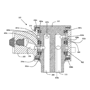
[0025] FIG. 3 is a
cross-section view of the steering valve 100 taken along D-D of
FIG. 2, and depicts (i) an opening 304a leading to port A 104, (ii) an opening
304b
leading to port B 106, (iii) an opening 307a leading to port C 108, (iv) an
opening 308b
leading to port D 110, (v) an opening 307b leading to port C 108, and (vi) an
opening
308a leading to port D 110. Steering valve 100 also comprises connectors, or
passageways, that facilitate a fluid connection (i) between port A 104 and
either port C
CA 02964150 2017-04-07
WO 2016/057888
PCT/US2015/054875
108 or port D 110, and (ii) between port B 106 and either port D 110 or port C
108. In
operation, the housing 102 may be rotated around the spool 112 until opening
304a of
port A 104 aligns with one of either opening 307a of port C 108 or opening
308a of port
D 110. This rotation of housing 102 will similarly align opening 304b of port
B 106 with
the other of either opening 307b of port C 108 or opening 308b of port D 110.
Thus,
when opening 304a of port A 104 is aligned with opening 307a of port C 108,
then
opening 304b of port B 106 will be aligned with opening 308b of port D 110,
and vice
versa. The schematic in FIG. 14 depicts the operation of steering valve's 100
various
ports.
[0026] The cross-
sectional view of FIG. 3 depicts the specific condition of steering
valve 100, where housing 102 has been rotated around spool 112 from its
default/neutral
position to a first position. This first position of housing 102 with respect
to spool 112
allows connectors 302a and 302b (or, rather, passageways 302a and 302b) to
form fluid
connections between port A 104 and port C 108 via openings 304a and 307a, and
between
port B 106 and port D 110 via openings 304b and 308b, respectively (the "First
Position"). It should be appreciated, however, that opening 307b is fluidly
connected to
port C 108 via a third connector/passageway (not shown in FIG. 3) and that
opening 308a
is fluidly connected to port D 110 via a fourth connector/passageway (also not
shown in
FIG. 3). Thus, when housing 102 is rotated around spool 112 from its
default/neutral
position to a second position (not shown), the third connector/passageway will
establish a
fluid connection between port B 106 and port C 108 via openings 304b and 307b,
and the
fourth connector/passageway will establish a fluid connection between port A
104 and
port D 110 via openings 304a and 308a (the "Second Position").
[0027] It should be
appreciated that the degree of rotation needed to orient housing
102 with respect spool 112 into either the First Position or Second Position
is
customizable by an end-user. Thus, the end-user can vary the degree of
rotation needed
to orient housing 102 into the First Position and Second Position by altering
the geometry
and/or placement of openings 304a, 307a, 308a, 304b, 308b, and 307b. This
allows
utilization of steering valve 100 in a number of different applications where
different
degrees of housing 102 rotation with respect to spool 112 is desirable.
6
CA 02964150 2017-04-07
WO 2016/057888
PCT/US2015/054875
[0028] Importantly,
steering valve 100 includes two valve planes. For example, the
steering valve 100 is configured such that port A 104 forms a fluid connection
with one of
port C 108 or port D 110 at a different level plane as compared to the
simultaneous fluid
connection formed between port B 106 and the other of port D 110 or port C
108. The
two valve planes are separated by a seal 306, which contains any leakage and
for prevents
cross-leakage. Thus, leakage from port A 104 is prevented from entering port B
106,
while leakage from port B 106 is prevented from entering port A 104. By
separating the
fluid connections into two different planes and effectively creating two
different valves
that are each impervious to cross-leakage from the other, the need for
extremely close
tolerances when manufacturing the steering valve 100 is reduced. This is
because some
leakage may be more tolerable as compared to a design in which both its port A
and port
B are disposed on a single plane without a seal separating the two ports.
[0029] In one
example, steering valve 100 further comprises a seal 306a above the top
valve plane, as well as seal 306b below the bottom valve plane. In this
example, seals
306, 306a, and 306b are dynamic seals. In another example, the seals 306, 306a
and/or
306b are thermoset seals. In yet another example, the seals 306, 306a and/or
306b are 0-
rings. It should be appreciated that other suitable types of seals may be used
to prevent
cross-leakage between port A 104 and port B 106. FIG. 8 and FIG. 9 depict the
orientation the top valve plane and bottom valve plane with respect to the
sleeve 402 and
spool 112, respectively.
[0030] FIG. 4
illustrates an exploded view of the steering valve 100 of FIG. 1,
including the housing 102, port A 104, port B 106, the spool 112, and seals
306, 306a and
306b. The steering valve 100 further includes a sleeve 402 for receiving the
spool 112
inside the housing 102. Sleeve 402 is configured to rotate in conjunction with
housing
102, for example, by way of the anti-rotational element 315 depicted in FIG.
3. The
sleeve 402 may be manufactured using metals or other suitable material. In one
example,
sleeve 402 is manufactured using a corrosion resistant form of steel, such as
stainless
steel. Moreover, sleeve 402 is configured to receive seals 403a, 403b, and
403c on an
external surface thereof. As depicted in the example of FIG. 3, seals 403a,
403b, and
403c establish a seal between the outer surface of sleeve 402 and the inner
surface of
housing 102. In this example, seals 403a, 403b, and 403c are static seals and
provide
additional separation and leakage protection.
7
CA 02964150 2017-04-07
WO 2016/057888
PCT/US2015/054875
[0031] FIG. 4
depicts another example of steering valve 100 where washer assembly
410 is utilized. In this example, washer assembly 410 comprises washer 410a,
washers
410b, washers 410c, and snap ring 410d. Washer 410a is a washer designed to
provide a
compensating spring force or absorb shock when under load, such as a wave
washer.
Washers 410b may be made of a hard material having slippery outer surfaces
that allow
rotation of one of washers 410c there between, for example, metal washers with
a slick or
smooth outer surface. Washers 410c may be any type of thrust bearings or self-
lubricating thrust washers, such as a Teflon ring. FIG. 3 depicts an example
where
washers 410c are Teflon rings, and where one such Teflon ring is disposed
between the
lip of spool 112 and the lip of sleeve 402. Lastly, snap ring 410d is utilized
to securely
hold together the inner components of steering valve 100.
[0032] FIG. 5
illustrates the housing 102 of the steering valve 100. FIG 6 is a cut-
out view of the housing 102, illustrating port B 106 leading to opening 304b
in a top
plane on the inside of housing 102. FIG 7 is a cut-out view of the housing
102,
illustrating port A 104 leading to opening 304a in a bottom plane on the
inside of housing
102.
[0033] FIG. 8
illustrates the sleeve 402 of FIG. 4. The sleeve 402 includes a first
upper opening 802 on a first or upper plane 804 for enabling a fluid
connection between
port B 106 and one of port C 108 or port D 110 depending on the orientation of
the
housing 102. The sleeve 402 further includes a second upper opening 806 on the
first/upper plane 804 for enabling a fluid connection between port B 106 and
the other
one of port C 108 or port D 110. The sleeve 402 further includes a second or
lower plane
810 including a first lower opening 808 and a second lower opening (not shown)
for
enabling a fluid connection between port A 104 and port C 108 as well as
between port A
104 and port D 110, depending on the orientation of the housing 102. FIG. 8
also depicts
an exemplary orientation of seals 403a, 403b, and 403c on the sleeve 402
relative to
planes 804 and 810. It should be appreciated that the geometry and orientation
of the first
and second upper openings (802 and 806) as well as the first and second lower
openings
(808 and not shown) with respect to sleeve 402 is customizable by the end-user
and
dependent on the location of the other openings in housing 102 and spool 112,
as
discussed above.
8
CA 02964150 2017-04-07
WO 2016/057888
PCT/US2015/054875
[0034] FIG. 9
illustrates the spool 112 of FIG. 4. The spool 112 has a lower plane
902 including first and second lower openings 904 and 906 corresponding to the
first
lower opening 808 and the second lower opening (not shown) of the sleeve 402
for
enabling a fluid connection between port A 104 and port C 108 as well as
between port A
104 and port D 110, depending on the orientation of the housing 102. The spool
112 also
has an upper plane 908 including a first upper opening (not shown) and a
second upper
opening (also not shown) corresponding to the first upper opening 802 and
second upper
opening 806 of the sleeve 402 for enabling a fluid connection between port B
106 and
port C 108 as well as between port B 106 and port D 110, depending on the
orientation of
the housing 102. Note, first and second lower openings 904 and 906 are
depicted in FIG.
3 as opening 307a leading to port C 108 and opening 308a leading to port D
110. The
spool's 112 first and second upper openings (neither of which are depicted in
FIG. 9) are
also depicted in FIG. 3 as opening 307b leading to port C 108 and opening 308b
leading
to port D 110. Again, the specific geometry and orientation of the various
openings on
any of the housing 102, spool 112, and sleeve 402 are customizable and may
depend on
an end-user's desired application.
[0035] FIG. 10
illustrates a side view of the steering valve 100. FIGs. 11-13
illustrate cross-sectional top views of steering valve 100 along A-A, B-B, and
C-C of
FIG. 10, respectively.
[0036] Thus, in
operation steering valve 100 works as follows. For example, the pilot
of an airplane may rotate the steering wheel intending to turn the landing
gear at the nose
of the plane in a certain direction. This action causes movement in the
steering column,
which in turn translates to rotation of housing 102 in a certain direction.
Rotation of
housing 102 in that direction causes (i) alignment of opening 304a of port A
104 with one
of either opening 307a of port C 108 or opening 308a of port D 110 and,
similarly (ii)
alignment of opening 304b of port B 106 with the other of either opening 307b
of port C
108 or opening 308b of port D 110. Alignment of port A 104 with port C 108 and
port B
106 with port D 110 causes the nose wheel steering actuator to steer the
landing gear in a
first direction. On the other band, alignment of port A 104 with port D 110
and port B
106 with port C 108 causes the nose wheel steering actuator to steer the
landing gear in
the opposite direction.
9
CA 02964150 2017-04-07
WO 2016/057888
PCT/US2015/054875
[0037] To the
extent that the term "includes" or "including" is used in the
specification or the claims, it is intended to be inclusive in a manner
similar to the term
"comprising" as that term is interpreted when employed as a transitional word
in a claim.
Furthermore, to the extent that the term "or" is employed (e.g., A or B) it is
intended to
mean "A or B or both." When the applicants intend to indicate "only A or B but
not both"
then the term "only A or B but not both" will be employed. Thus, use of the
term "or"
herein is the inclusive, and not the exclusive use. See, Bryan A. Garner, A
Dictionary of
Modern Legal Usage 624 (2d. Ed. 1995). Also, to the extent that the terms "in"
or "into"
are used in the specification or the claims, it is intended to additionally
mean "on" or
"onto." Furthermore, to the extent the term "connect" is used in the
specification or
claims, it is intended to mean not only "directly connected to," but also
"indirectly
connected to" such as connected through another component or components.
[0038] While the present application has been illustrated by the description
of
embodiments thereof, and while the embodiments have been described in
considerable
detail, it is not the intention of the applicants to restrict or in any way
limit the scope of
the appended claims to such detail. Additional advantages and modifications
will readily
appear to those skilled in the art. Therefore, the application, in its broader
aspects, is not
limited to the specific details, the representative apparatus and method, and
illustrative
examples shown and described. Accordingly, departures may be made from such
details
without departing from the spirit or scope of the applicant's general
inventive concept.