Note: Descriptions are shown in the official language in which they were submitted.
BRAZING SHEET
CROSS REFERENCE TO RELATED APPLICATIONS
[0001] This application claims priority to U.S. Provisional Patent Application
Serial No. 62/063,267
filed October 13, 2014.
BACKGROUND
[0002] Heat exchangers, such as radiators and heater cores, are used for
thermal energy transfer
from an operating system, such as an automotive engine, to the environment.
Coolant or cooling
fluid is used as a medium to bring the heat from the operating system to the
heat exchanger.
Depending upon the chemical additives, a coolant can cause corrosion on the
aluminum tube used
for the heat exchanger. Therefore brazing sheet products for this type of heat
exchanger
applications, such as tubestock or header plate, have a liner on the coolant
side, called waterside
liner, which provides corrosion protection to the core of the aluminum tube.
SUMMARY
[0003] In one embodiment, a brazing sheet comprises: a core layer, a braze
liner on the first side of
the core layer; and a waterside liner on the second side of the core layer.
The core layer is
comprised of a 3xxx series aluminum alloy. The waterside liner is an aluminum
alloy comprising:
7-20wt% Zn; up to 0.25wt% Si; up to 0.1wt% Cu; up to 0.25wt% Mn; up to 0.1wt%
Mg; and up to
0.1wt% Cr.
1
CA 2964452 2018-12-13
CA 02964452 2017-04-12
WO 2016/061074 PCT/US2015/055287
[0004] In some embodiments, the waterside liner comprises 7-20wt% Zn; up
to
0.25wt% Si; up to 0,1wt% Cu; up to 0,25wt% Mn; up to 0,1wt% Mg; and up to
0.1wt% Cr,
the remainder being aluminum, incidental elements and impurities,
[0005] In some embodiments, the waterside liner comprises 10-20wt%Zn. In
some
embodiments, the waterside liner comprises 12-20wt%2n. In some embodiments,
the
waterside liner comprises 15-20wto/an. In some embodiments, the waterside
liner
comprises 16-20w0,4,,Zn. In some embodiments, the waterside liner comprises 9-
12wt%Zn,
[0006] In some embodiments, the core layer comprises; 0,5-1,25wt% Si; 0õ5-
1.25wt% Cu; 0.5-2.0wt%In; up to 0,15wt% Mg; up to 0,1wt% Cr; up to 0.1wt% Zn;
and
0.1-0.2wt% Ti.
[0007] In some embodiments, the core layer comprises: 0.5415wt% Si; 0,5-
1,25wt% Cu; 0,5-2.0wt%Mn; up to 0,15wt% Mg; up to 0.1.wt% Cr; up to
0,11,,vtV3Zn; and
0.1-02wt% Ti, the remainder being aluminum, incidental elements and
impurities,
[0008] In some embodiments, the braze liner comprises a 4,xxx series
aluminum
alloy,
[0009] In some embodiments, the brazing sheet has a thickness of 60-180
microns.
in some embodiments, the brazing sheet has a thickness of 60-150 microns. In
some
embodiments, the brazing sheet has a thickness of 80-150 microns, In some
embodiments,
the brazing sheet has a thickness of 60-100 microns. In some embodiments, the
brazing
sheet has a thickness of 60-180 microns.
[0010] In some embodiments, the brazing sheet has a thickness and the
waterside
liner comprises 1-15% of the thickness. In some embodiments, the brazing sheet
has a
thickness and the waterside liner comprises 7-15% of the thickness In some
embodiments,
2
CA 02964452 2017-04-12
WO 2016/061074 PCT/US2015/055287
the brazing sheet has a thickness and the waterside liner comprises 7-10% of
the thickness,
In some embodiments, the brazing sheet has a thickness and the waterside liner
comprises
5-15% of the thickness. In some embodiments, the brazing sheet has a thickness
and the
waterside liner comprises 5-10% of the thickness.
[0011] In one embodiment, a brazing sheet comprises: a core layer, a braze
liner on
the first side of the core layer; and a layer of zinc on the second side of
the core layer. The
core layer comprises a 3xxx series aluminum alloy,
[001.2] In some embodiments, the layer of zinc comprises 99.9 wt% Zn.
[0013] In some embodiments, the brazing sheet has a thickness and the
layer of zinc
comprises less than 2% of the thickness.
[0014] in some embodiments, the core layer comprises: 0.5-1,25wt% Si; 05-
1.25wt% Cu; 0,5-2.0wt% Mn; up to 0,15wt% Mg; up to 0,1wt% Cr; up to 0,1wt% Zn;
and
0,1-0.2-wt% Ti.
[0015] In some embodiments, the core layer comprises: 0,5-1.25wt% Si; 0,5-
1,25wt% Cu; 0,5-2.0wt% Mn; up to 0,15wt% Mg; up to 0,1wt% Cr; up to 0.1wt% Zn;
and
0,1-0,2wt% Ti, the remainder being aluminum, incidental elements and
impurities,
[0016] In some embodiments, the brazing sheet has a thickness of 60-180
microns,
In some embodiments, the brazing sheet has a thickness of 60-150 microns. In
some
embodiments, the brazing sheet has a thickness of 80-150 microns, In some
embodiments,
the brazing sheet has a thickness of 60-100 microns, In some embodiments, the
brazing
sheet has a thickness of 60-180 microns.
[0017] It will be appreciated by those of ordinary skill in the art that
the brazing
sheet disclosed can be embodied in other specific forms without departing from
the spirit
3
CA 02964452 2017-04-12
WO 2016/061074
PCT/US2015/055287
or essential character thereof. The presently disclosed embodiments are
therefore
considered in all respects to be illustrative and not restrictive, Reference
is now made to
the accompanying drawings, which at least assist in illustrating various
pertinent features
of the disclosure.
BRIEF DESCRIPTION OF THE DRAWINGS
[001.8] Figure 1. is a schematic cross-section view of one embodiment of a
brazing
sheet,
[0019] Figure 2 is a schematic cross-section view of another embodiment of
a
brazing sheet
[0020] Figure 3 is a schematic cross-section view of a further embodiment
of a
brazing sheet,
[0021] Figure 4 is a schematic cross-section view of yet another embodiment
of a
brazing sheet,
[00221 Figure 5 is a graph iliustrating simulated pre-braze zinc
distribution
according to a prior art brazing sheet.
[0023] Figure 6 is a graph illustrating simulated pre-braze zinc
distribution
according to another embodiment of a brazing sheet.
[0024] Figure 7 is a graph illustrating simulated pre-braze zinc
distribution
according to a further embodiment of a brazing sheet
[0025] Figure 8 is a graph illustrating simulated pre-braze zinc
distribution
according to yet another embodiment of a brazing sheet.
[0026] Figure 9 is a graph illustrating simulated post-braze zinc
distribution
according to the prior art referenced in Figure 5,
4
CA 02964452 2017-04-12
WO 2016/061074 PCT/US2015/055287
[0027] Figure 10 is a graph illustrating simulated post-braze zinc
distribution
according to the embodiment referenced in Figure 6.
[0028] Figure 11 is a graph illustrating simulated post-braze zinc
distribution
according to the embodiment referenced in Figure 7.
[0029] Figure 12 is a graph illustrating simulated post-braze zinc
distribution
according to the embodiment referenced in Figure 8,
[0030] Figure 13 is a chart showing the differences in zinc levels between
the liner
surfaces and cores of the embodiments referenced in Figures 5-12,
[0031] Figure 14 is a graph showing the simulated pre-braze zinc
distributions of
four additional embodiments,
[0032] Figure 15 is a graph showing the simulated pre-braze copper
distributions of
the four embodiments referenced in Figure 14,
[0033] Figure 16 is a graph showing the simulated pre-braze silicon
distributions of
the four embodiments referenced in Figure 14,
[0034] Figure 17 is a graph showing the simulated post-braze zinc
distributions of
the four embodiments referenced in Figure 14.
[0035] Figure 18 is a graph showing the simulated post-braze copper
distributions
of the four embodiments referenced in Figure 14.
[0036] 'Figure 19 is a graph showing the simulated post-braze silicon
distributions of
the four embodiments referenced in Figure 14,
[0037] Figure 20shows properties of two embodiments of brazing sheet,
[0038] Figure 21 shows the zinc distributions of the two embodiments
detailed in
Figure 21.
CA 02964452 2017-04-12
WO 2016/061074
PCT/US2015/055287
[0039] Figure 22 shows the results of an OY corrosion test on the two
embodiments
detailed in Figure 21.
[0040] Figure 23 shows samples according to both embodiments shown and
described in Figures 21 and 22 after completing an immersion test.
[0041] Figure 24 shows the samples of Figure 23 after completing the
immersion
test for 60 days.
DESCRIPTION
[00421 it will be appreciated by those of ordinary skill in the art that
the disclosed
brazing sheet can be embodied in other specific forms without departing from
the spirit or
essential character thereof. The presently disclosed embodiments are therefore
considered in all respects to be illustrative and not restrictive. Reference
is now made to
the accompanying drawings, which at least assist in illustrating various
pertinent features
of the disclosure.
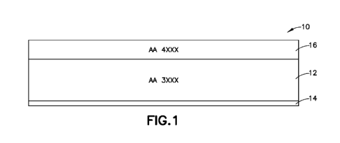
[0043] Figure 1 illustrates a brazing sheet according to one embodiment. A
core
layer 12 comprising 3xxx series aluminum alloy has a braze liner 16 on a first
side and
waterside liner 1.4 on a second side,
[0044] In some embodiments, the core layer comprises: Si 0.5-1,25wt%, Cu
0.5-
1.25wt%, Mn 0.5-2.0wtck, Mg up to 0,15wt%, Cr up to 0,1wt%, Zri up to 0.1wt%,
Ti
0.21,,vt%, the rest Al and inevitable impurities,
[0045] In some embodiments, the waterside liner comprises aluminum alloy
comprising Zn 7-20wt%, Si up to 0,25wt%, Cu up to 0.1wt%, Mn up to 0.25wt%, Mg
up to
0.1wt0/05Cr up to 0.1µ4.1%, and inevitable impurities,
6
CA 02964452 2017-04-12
WO 2016/061074 PCT/US2015/055287
[0046] In some embodiments, the braze liner comprises a 4xxx series
aluminum
100471 Figure 2 illustrates a brazing sheet according to another
embodiment. A
second liner .22 is shown between the braze liner 16 and the core layer 12.
[00481 Figure 3 illustrates a brazing sheet according to yet another
embodiment A
core layer 12 comprising 3mot series aluminum alloy has a braze liner 16 on a
first side and
waterside liner 32 on a second side. In this embodiment, the waterside liner
can be
commercial purity Zri comprising Ziri 99.9wt% and inevitable impurities. The
layer can be
applied by using a zinc spray process on the second side of the core, using a
coating process
on the second side of the core, or cast/roll bonding a layer on the second
side of the core.
[0049] The embodiment shown in Figure 4 includes a second layer of
commercial
purity zinc 42 between the core layer and the braze liner 16.
[0050] In some embodiments of the brazing sheet shown in Figure 2, the
second
liner 22 comprises commercial purity (99.9wt%) zinc.
[00511 Since zinc in aluminum lowers the melting point of the Al-Zri alloy
there can
be a high risk of melting the high zinc containing layer in the braze process
before or at a
braze temperature around 600C. However, the zinc in the waterside liner can be
redistributed through the fabrication process by diffusing from the waterside
liner into the
core, which reduces the initial zinc concentration in the waterside liner and,
therefore,
makes it possible to go through the high temperature brazing process without
melting. The
fabrication process can be any thermal or mechanical process known in the art
to produce
brazing sheet, such as annealing, hot rolling and cold rolling. The amount of
zinc diffusion
7.
CA 02964452 2017-04-12
WO 2016/061074 PCT/US2015/055287
that will occur depends on factors known to those of ordinary skill in the
art, such the type,
time and temperature of processing steps.
[0052/ Examples of the zinc distribution of a 150 micron brazing sheet
according to
an embodiment before going through the fabrication process and before brazing
are shown
in Figures 5-8. (The graphs only show from mid thickness of the brazing sheet
to the
waterside, tee 75-150 microns), Figure 5 illustrates the zinc distribution in
a brazing sheet
having a prior art waterside liner starting with 4,6wt% Zn. Figure 6
illustrates the zinc
distribution in a brazing sheet having a waterside liner starting withl2wt%
Zn. Figure 7
illustrates the zinc distribution in a brazing sheet having a waterside liner
starting with
16wt% Zn. Figure 8 illustrates the zinc distribution in a brazing sheet having
a waterside
liner starting with 99.5wt% Zn. The vertical boundary line in Figures 5-8
represents the
thickness of the brazing sheet where the core layer ends and the waterside
liner begins.
The higher the zinc concentration in the waterside liner, the thinner the
waterside liner can
be while still providing adequate protection to the core. This enables the
core to be thicker
and provide higher strength to the brazing sheet, while the brazing sheet
maintains the
same thickness
[00531 The zinc distributions after braze are shown in Figures 9-12, Figure
9
illustrates the post-braze zinc distribution in a brazing sheet having a prior
art waterside
liner starting with 4.6wt% Zn, Figure 10 illustrates the post-braze zinc
distribution in a
brazing sheet having a waterside liner starting with 12wt% Zn. Figure 11.
illustrates the
post-braze zinc distribution in a brazing sheet having a waterside liner
starting with
1.6wt% Z11, Figure 12 illustrates the post-braze zinc distribution in a
brazing sheet having a
waterside liner starting with 99.5wt% Zn.
8
CA 02964452 2017-04-12
WO 2016/061074 PCT/US2015/055287
[0054] The difference in zinc level between the liner surface and core are
shown in
the table in Figure 13, The zinc levels shown in the Table indicate that
initial zinc levels are
significantly reduced through thermal and mechanical process, Le., from 99.5%
to
11345%, 16% to 8.735%, 12% to 8.179%, and 4,6% to 4.357% with the
corresponding
clad ratio, In this way the risk of melting in the braze process is
significantly reduced,
which makes it possible to use a high zinc containing alloy for waterside
liner application,
[0055] The simulated zinc distribution also shows for the high zinc
containing liner
the low clad ratio can provide larger difference in the zinc level between the
liner surface
and tube center for the post braze material, which is expected to provide
better corrosion
protection to a tube formed by brazing sheet according to some embodiments.
[0056] Some embodiments provide high strength and enhanced corrosion
protection to enable a light gauge product.
[0057] In another example, an embodiment of a 100-micron thick brazing
sheet is
used as an as a radiator/heater core tube. Figures 14-16 show the zinc, copper
and silicon
distributions, respectively, before going through the fabrication process and
before
brazing. Figure 14 illustrates the zinc distribution in brazing sheet having
waterside liners
starting with 4.6wt% Zn, 12wt% Zn, 16wt% Zn. and 99.5wt% Zn. The waterside
liner
comprises 30% of the thickness of the brazing sheet having a waterside liner
starting with
4.6wt% Zn (prior art). The waterside liner comprises 10% of the thickness of
the brazing
sheet having a waterside liner starting with 12wt% Zn. The waterside liner
comprises
7,5% of the thickness of the brazing sheet having a waterside liner starting
with 16wt% Zn.
The waterside liner comprises 1% of the thickness of the brazing sheet having
a waterside
liner starting with 99.9wt% Zn,
9
CA 02964452 2017-04-12
WO 2016/061074 PCT/US2015/055287
[0058] Figure 15 illustrates the copper distribution in brazing sheet
having
waterside liners starting with 4,6wt% Zn, 12wt% Zn, and 16wto/0 Zn, Figure 16
illustrates
the silicon distribution in brazing sheet having a waterside liners starting
with 4,6wt% Zn,
121,,vt% Zn, and 16wt% Zit
[0059] The alloying element distributions of the post braze material are
shown in
the graphs in Figures 17-19, Figure 17 illustrates the zinc distribution,
Figure 18 illustrates
the copper distribution and Figure 19 illustrates the silicon distribution.
[0060] The vertical lines in Figures 14-19 represent the thickness of the
brazing
sheet where the core layer ends and the waterside liner begins,
[0061] Four liner thicknesses with four zinc levels are shown Figures 14-
19, With a
high zinc level, a low clad ratio can be used to provide sufficient corrosion
protection for a
tube formed with the brazing sheet according to some embodiments.
[0062] The above diffusion simulations show waterside liners with
relatively higher
zinc levels and lower clad ratios can generate larger differences in zinc
concentrations
between the surface of the waterside liner and core than waterside liners with
relatively
low zinc levels and higher clad ratios. The larger differences in zinc
concentrations can
provide better corrosion protection to the core. A low clad ratio enables a
high core
thickness, which can help increase the strength of the tube material,
[0063] In some embodiments, a zinc-containing liner, comprising one of the
alloys
disclosed above, is on the first side of the core, between the braze liner and
core, to provide
the corrosion protection on the air side of the brazing sheet
[0064] Figure 20 shows properties of a lab made heater core tube made from
brazing sheet according to two embodiments. Both embodiments had a thickness
of about
CA 02964452 2017-04-12
WO 2016/061074
PCT/US2015/055287
0.1mm. the dad ration of the braze liner was about 20% and the clad ratio of
the waterside
liner was about 11 % The braze liner in both embodiments was comprised of the
same
alloy. The water side liner in both embodiments was comprised of the same
alloy. Two
different core alloys were tested.
[0065] Figure
21 shows the zinc distributions of the two embodiments detailed in
Figure 21, With respect to both embodiments, the zinc diffused into the core
in the
fabrication process, but the gradient of the zinc diffusion is still steep.
The difference
between the zinc level in the waterside liner and the core is significant and
generates a
good corrosion potential difference such that the water side liner can provide
adequate
corrosion protection to the core in both embodiments.
[0066] Results
of an OY corrosion test are shown in Figure 22. The sample shown
had gone through the OY corrosion test for 250 hours. The OY test temperature
was 95C
and a flow rate of about 1. liter per minute, The OY solution composition was
as follows:
Chemical product Required quantity for one liter of OY water
NaC1 225.50
mg
Na2SO4 89,00
ntg
C 2oC1..,* 0 265
mg
FeC1306I-I 0 145,00
mg
Total CI 195 ppm
11
CA 02964452 2017-04-12
WO 2016/061074 PCT/US2015/055287
[0067] Figure 23 shows samples according to both embodiments shown and
described in Figures 21 and 22 after completing an immersion test. The
corrosion attack is
on the water side liner only. The core did not corrode.
[0068] Figure 24 shows the samples of Figure 23 after completing the
immersion
test for 60 days,
[00691 A brazing sheet is a metal sheet having multiple, distinct layers,
including at
least one brazing liner or layer.
[0070] A braze liner is a layer of a brazing sheet comprising a brazing
material.
[00711 A core layer is a layer of a brazing sheet. The core layer has a
first side and a
second side. A braze liner is on a first side or both sides of the core layer.
The braze liner
may be directly on the core layer or there may be an interliner between the
core and the
braze liner,
[00721 A waterside liner is a layer of a brazing sheet on one side of the
core layer.
The purpose of the waterside liner is to protect the core from corrosion cause
by coolant
flowing through the inside of a tube made from the brazing sheet.
[0073] As used herein, "incidental elements" means those elements or
materials that
may optionally be added to the alloy to assist in the production of the alloy.
Examples of
incidental elements include casting aids, such as grain refiners,
[0074] Grain refiners are inoculants or nuclei to seed new grains during
solidification of the alloy, An example of a grain refiner is a 9,5 mm (3/8
inch) rod
comprising 96% aluminum, 3% titanium (Ti) and 1% boron (B), where virtually
all boron
is present as finely dispersed TiB2 particles. During casting, the grain
refining rod is fed in-
line into the molten alloy flowing into the casting pit at a controlled rate.
The amount of
12
CA 02964452 2017-04-12
WO 2016/061074 PCT/US2015/055287
grain refiner included in the alloy is generally dependent on the type of
material utilized for
grain refining and the alloy production process. Examples of grain refiners
include Ti
combined with B (e.g., TIB2) or carbon (TiC), although other grain refiners,
such as AI-Ti
master alloys may be utilized. Generally, grain refiners (e.g., boron) may be
added to the
alloy in an amount of ranging from 0.0003 wt. % to 0.03 wt. %, depending on
the desired
as-cast grain size. In addition, Ti may be separately added to the alloy in an
amount up to
0.03 wt. % to increase the effectiveness of grain refiner. When Ti is included
in the core
alloy, it is generally present in an amount of up to about 0.10 or 0.20 wt, %.
[007S1 Incidental elements may be present in minor amounts, or may be
present in
significant amounts, and may add desirable or other characteristics on their
own without
departing from the alloy described herein, so long as the alloy retains the
desirable
characteristics described herein. It is to be understood, however, that the
scope of this
disclosure should not/cannot be avoided through the mere addition of an
element or
elements in quantities that would not otherwise impact on the combinations of
properties
desired and attained herein.
[0076] As used herein, impurities are those materials that may be present
in the
alloy in minor amounts due to, for example, the inherent properties of
aluminum and/or
leaching from contact with manufacturing equipment. Iron (Fe) is an example of
an
impurity generally present in aluminum alloys. The Fe content of the alloy
should
generally not exceed about 025 wt, %. In some embodiments, the Fe content of
the alloy is
not greater than about 0.15 wt. %, or not greater than about 0,10 wt. %, or
not greater than
about 0,08 wt. %, or not greater than about 0,05 wt. % or about 0.04 wt, %.
13
CA 02964452 2017-04-12
WO 2016/061074
PCT/US2015/055287
[0077] The alloys and tempers mentioned herein are as defined by the
American
National Standard Alloy and Temper Designation System for Aluminum ANSI I-135A
and
"the Aluminum Association International Alloy Designations and Chemical
Composition
Limits for Wrought Aluminum and Wrought Aluminum Alloys as revised January
2015.
[0078] Except where stated otherwise, the expression "up to" when referring
to the
amount of an element means that that elemental composition is optional or
incidental and
includes a zero amount of that particular compositional component. Unless
stated
otherwise, all compositional percentages are in weight percent (wt. %J.
14