Note: Descriptions are shown in the official language in which they were submitted.
CA 02964497 2017-04-13
DESCRIPTION
TITLE OF THE INVENTION
LED LAMP UNIT
TECHNICAL FIELD OF THE INVENTION
The present invention relates to an LED lamp unit.
BACKGROUND OF THE INVENTION
In recent years, various performance of the illuminating LED lamp has
been improved considerably due to the continuous development of the LED
technology. The LED lamp has become the trend in the future of the light
source
since it has a number of advantages such as long lifetime, high luminous
efficiency,
no UV radiation and lower energy consumption.
However, unlike the incandescent lamp and the like which could
implement 360 degree omnidirectional illumination, the LED light source has
directivity, so its illuminating effect, to a certain extent, is impacted when
it replaces
traditional light source such as the incandescent lamp or the like as a light
source,
especially when the LED is manufactured to be a daylight lamp having a
traditional
tube-shape, for example the "LED daylight lamp" disclosed in the Chinese
patent
which the publication number is CN102022651A. This LED daylight lamp comprises
a lampshade, LED light source -assembly, an LED driving assembly, two end caps
and a heat dissipating housing. The lampshade is connected to the heat
dissipating
housing, and the two end caps cover the lampshade and the heat dissipating
housing which have been connected at their two ends respectively. The cross
sections of the lampshade and the heat dissipating housing are both arc-
shaped,
and the lampshade and the heat dissipating housing form a cavity in which the
LED
light source components and the LED driving component are located. In this LED
1
CA 02964497 2017-04-13
daylight lamp, the LEDs have to be arranged within a plane so as to meet the
requirements for their heat dissipation. Thus, its light emitting area could
merely
cover 180 degree rather than 360 degree (i.e., it emits light from a plane
instead of
emitting light omnidirectionally), although it has a long straight tube-shape
like the
daylight lamp. Therefore, the LED daylight lamp in the prior art could not
implement
360 degree omnidirectional illumination while meeting the requirements for the
heat
dissipation since the heat dissipating area and the light emitting area are
contradictory.
BRIEF SUMMARY OF THE INVENTION
The present invention aims to solve the technical problem of providing an
LED lamp unit that could implement omnidirectional illumination as well as has
good
heat dissipation performance.
In order to solve the technical problem mentioned above, the present
invention provides technical solutions as follows. The present invention
provides an
LED lamp unit comprising a light-emitting body having a hollow tube shape and
a
translucent cover enclosing the light-emitting body at its outside with a
space
therebetween. The light-emitting body and/or the translucent cover have LED
light-
emitting elements fixed on them. The LED lamp unit is characterized in that:
The two
ends of the light-emitting body and the translucent cover have end caps fixed
and
connected to them. The end caps have opening holes at their centers which
connect
a hollow cavity inside the light-emitting body to external environment. At
least one
end of the light-emitting body is provided with an electrical connection
component
which extends out of the end cap. The LED light-emitting elements on the light-
emitting body are connected to the electrical connection component. The end
cap at
the end that has electrical connection component is provided with a
circumferential
2
CA 02964497 2017-04-13
surface which extends outwardly in the same direction as the extending
direction of
the light-emitting body and the translucent cover, and the circumferential
surface is
provided with ventilation holes which connect the hollow cavity inside the
light-
emitting body to outside air.
In order to make the overall structure more reasonable, the outer end of
the circumferential surface of the end cap at the end that has electrical
connection
component is closed, and the outer end of the circumferential surface which is
closed has a hole from which the electrical connection component protrudes.
To facilitate the connection between the lamp units, when only one end of
the LED lamp unit has the electrical connection component, the end cap at the
end
that has no electrical connection component is also provided with a
circumferential
surface which extends outwardly in the same direction as the extending
direction of
the light-emitting body and the translucent cover, and the circumferential
surface is
provided with ventilation holes which connect the hollow cavity inside the
light-
emitting body to outside air.
Preferably, the outer end of the circumferential surface of the end cap at
the end of the LED lamp unit that has no electrical connection component is
closed.
In order to improve the light-emitting efficiency and the brightness
uniformity, the outer surface of the light-emitting body is coated with
reflective layer
or fluorescent powder.
The end caps are provided with grooves for accommodating and fixing the
light-emitting body and the translucent cover respectively to facilitate the
fixing.
Preferably, the LED Light-emitting elements are fixed on the outer surface
of the light-emitting body.
3
CA 02964497 2017-04-13
Compared with the technology in prior art, the present invention has
advantages as follows: The LED lamp unit has a simple structure, implements
360
degree omnidirectional illumination, and has good heat dissipation performance
due
to the fact that it is provided with a heat dissipation channel in
communication with
the outside air, thereby increasing the service life of the LED lamp unit.
Additionally,
a plurality of this LED lamp units could be connected to each other to form
lamps
with various lengths or various shapes, and thus the range of applications is
widened.
BRIEF DESCRIPTION OF THE DRAWINGS
Fig. 1 is a perspective view of the LED lamp unit according to the first
embodiment of the present invention;
Fig. 2 is a sectional view of the LED lamp unit according to the first
embodiment of the present invention;
Fig. 3 is an exploded view of the LED lamp unit according to the first
embodiment of the present invention;
Fig. 4 is a perspective view of the LED lamp unit according to the second
embodiment of the present invention;
Fig. 5 is a sectional view of the LED lamp unit according to the second
embodiment of the present invention;
Fig. 6 is an exploded view of the LED lamp unit according to the third
embodiment of the present invention;
Fig. 7 is a sectional view of the LED lamp unit according to the third
embodiment of the present invention;
Fig. 8 is a perspective view of an LED lamp comprising the LED lamp unit
according to the first embodiment of the present invention;
4
CA 02964497 2017-04-13
Fig. 9 is a sectional view of an LED lamp comprising the LED lamp unit
according to the first embodiment of the present invention.
DETAILED DESCRIPTION OF THE INVENTION
In the following, further details of the present invention are described with
reference to the drawings and embodiments.
Embodiment 1
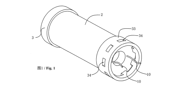
As illustrated in Fig. 1 to Fig. 3, the LED lamp unit according to the first
embodiment of the present invention comprises a light-emitting body 1 having a
hollow tube shape and a translucent cover 2. The light-emitting body 1 has
openings
at its two ends and a hollow cavity extending along its length. The light-
emitting body
1 may be metal, or transparent material such as plastic, ceramic, glass and
the like.
A plurality of LED light-emitting elements are fixed on the out surface of the
light-
emitting body 1. The plurality of LED light-emitting elements are electrically
connected to the connecting line or plug-in pieces at one end of the light-
emitting
body 1 through the printed circuit printed on the surface of the light-
emitting body 1.
As shown in Fig. 1 to Fig. 3, one end of the light-emitting body 1 in this
embodiment
is connected to a connecting line 10, and the plurality of LED light-emitting
elements
are connected to the connecting line 10. The out surface of the light-emitting
body 1
is coated with reflective layer or fluorescent powder layer so that the
luminous
efficiency of the light-emitting body 1 is improved and its brightness is more
uniform.
The light-emitting body 1 is enclosed by a translucent cover 2 at its outside.
The translucent cover 2 matches the light-emitting body, encloses the light-
emitting
body 1 at its outside and extends along with the light-emitting body 1 in the
same
direction with a space between them. A cavity is formed between the
translucent
cover 2 and the light-emitting body 1. The translucent cover 2 is made of
translucent
CA 02964497 2017-04-13
material. The two ends of the light-emitting body 1 and the translucent cover
2 are
enclosed by end caps 3 respectively and fixed to them. The end caps 3 include
two
circular grooves with a space therebetween which are provided to be inserted
by the
light-emitting body 1 and the translucent cover 2 respectively. And the end
caps 3
have opening holes 32 at their centers which connect the hollow cavity inside
the
light-emitting body 2 to the external environment.
As illustrated in Fig. 1, an end cap 3 at one end of the light-emitting body 1
has a circumferential surface 33 which extends outwardly in the same direction
as
the extending direction of the translucent cover 2 and the light-emitting body
1. The
circumferential surface 33 has ventilation holes 34 arranged evenly spaced in
the
axial direction of the circumferential surface 33. The connecting line 10
extends out
of the end cap 3 and is located outside the LED lamp unit. The outside air
enters one
of the end caps 3 through its ventilation holes 34 or the hole enclosed by the
circumferential surface 33, flows into the hollow cavity of the light-emitting
body 1
through the opening hole 32 of the end cap 3, and then exits through the
opening
hole 32 at the center of the other end cap 3 at the other end, thereby forming
a heat
dissipation channel in communication with the external environment. The end of
the
light-emitting body 1 that has the connecting line 10, i.e., the end with the
electrical
connection component, is required to be connected to an external electrical
connector or other lamp unit with its end surface, so this end must have the
circumferential surface 33 extending in the same direction as the extending
direction
of the light-emitting body 1 and the translucent cover 2. And the
circumferential
surface 33 must have holes, otherwise the heat dissipation channel cannot form
a
loop. The outer end of the circumferential surface at this end may be not
closed, or
may be closed as long as the outer end has a hole from which the electrical
6
CA 02964497 2017-04-13
connection component could protrude. And the end surface of the other end that
has
no electrical connection component may have no circumferential surface and the
end
cap 3 is connected to the external environment through the opening hole 32, or
may
have a circumferential surface 33. The outer end of the circumferential
surface 33
may be closed or not. Nevertheless, there must be ventilation holes 34 on the
circumferential surface 33 when the outer end of the circumferential surface
33 is
closed.
More than two LED lamp units described above may be connected to each
other so as to form a longer lamp tube. Alternatively, one LED lamp unit may
be
connected to a electrical connector through the electrical connection
component to
form an LED lamp. The LED Light-emitting elements may be arranged on the outer
surface of the light-emitting body 1, the interior surface of the translucent
cover 2, or
the outer surface of the translucent cover 2. Alternatively, the LED light-
emitting
elements may be arranged on both of the translucent cover and the light-
emitting
body, as long as the light-emitting surfaces of the LED light-emitting
elements face
to the cavity formed between the light-emitting body and the translucent
cover. In
addition, at least two of the light-emitting body 1, the translucent cover 2
and the end
caps may be formed integrally.
Embodiment 2
As illustrated in Fig 4 to Fig. 5, the LED lamp unit according to the second
embodiment of the present invention has the same structure as the LED lamp
unit
according to the first embodiment except for the fact that one end of the
light-emitting
body1 in the second embodiment has an electrical connection component which is
embodied as a pin 20, the end cap 3 at the end of the LED lamp unit 1 that has
the
pin 20 is provided with the circumferential surface 33, the outer end of the
7
CA 02964497 2017-04-13
circumferential surface 33 is closed, and the circumferential surface 33 is
provided
with ventilation holes 34. The end cap 3 on the other end of the light-
emitting body 1
and the translucent cover 2 have no circumferential surface. The rest portion
of the
LED lamp unit in this embodiment is the same as that of the first embodiment.
Embodiment 3
As illustrated in Fig 6 and Fig. 7, the LED lamp unit according to the third
embodiment has the same structure as the LED lamp unit according to the first
embodiment except for the fact that both ends of the light-emitting body 1
have
electrical connection components which are embodied as connecting lines 10,
the
end caps of both ends of the light-emitting body 1 and the translucent cover 2
have
circumferential surfaces 33 which have ventilation holes 34 on them. The outer
end
of the circumferential surfaces 33 of the end caps at two ends may be not
closed, or
may also be closed obviously as long as there are holes from which the
connecting
lines 10 could protrude. A plurality of the LED lamp units could be connected
to each
other to form a lamp with a long tube shape, and the length of the lamp may be
adopted as required.
Fig. 8 and Fig. 9 illustrate an LED lamp comprising the LED lamp unit
according to the first embodiment of the present invention. The LED lamp
includes
an electrical connector 5 on which two LED lamp units are fixed. The LED lamp
units
are connected to a driver in the electrical connector 5 through the connecting
lines
protruding from the end caps 3, such that the LED light-emitting elements on
the
light-emitting bodies 1 are driven to emit light. The end caps at other ends
of the LED
lamp units are connected to each other. Obviously, the person skilled in the
art could
deduced that a plurality of LED lamp units may be connected and fixed
together. The
LED lamp units may also be connected end to end so as to form an LED lamp with
a
8
CA 02964497 2017-04-13
circular shape or other shape. The user could make any combination of the LED
lamp units as required.
The LED lamp unit has a simple structure, implements 360 degree
omnidirectional illumination, and has a large light-emitting angle and high
light-
emitting efficiency. Moreover, the LED lamp unit is provided with a heat
dissipation
channel in communication with the outside air and thus heat dissipation
performance
is good, thereby increasing the service life of the LED lamp unit.
Additionally, a
plurality of this LED lamp units could be connected to each other to form
lamps with
various lengths or various shapes, and thus the range of applications is
widened.
Although the preferred embodiments of the present invention have been
described above in detail, the person skilled in the art should clearly
understand that
various modification and alteration to the present invention are possible. Any
modification, equivalent replacement and improvement within the spirits and
principles of the present invention all fall into the protection scope of the
present
invention.
9