Note: Descriptions are shown in the official language in which they were submitted.
CA 2964650 2017-04-20
281472
A LIGHTING DEVICE
TECHNICAL FIELD .
[0001] The present invention relates to an illumination device, more
particularly a lamp
tube in an illumination device.
BACKGROUND ART
[0002] LED (Light Emitting Diode) lamp tubes are also called light tubes, with
the light
source using LED as the illuminator. Existing LED lamp tubes mainly consist of
light
diffusing masks, substrate, power drivers and light emitting diodes. The
substrate is
mounted on the bottom inside the lamp tube, the light emitting diode is
mounted on the
substrate, and the light from the light emitting diode is transmitted from the
lamp tube,
thereby realizing illumination.
[0003] Typically, existing lamp tubes glue the substrate directly to the
bottom inside the
glass lamp tube, so the light emitting diode is close to the bottom of the
lamp tube. Not
only can traces of the adhesive be seen from the side or the back of this type
of lamp tube,
making it unsightly, the light emitted by the light emitting diode is
scattered everywhere
with a large emitting angle, so the light beam is not concentrated.
[0004] With the prices of the LED lamp tubes getting lower and lower, some
venues want
the light emitted from the LED lamp tube not to be scattered, but to have a
smaller emitting
angle and a more concentrated illumination.
[0005] Therefore, it is necessary to provide an improved solution to solve at
least one of
the problems described above.
SUMMARY
[0006] A primary objective of the present invention is to provide a lamp tube
with a
smaller light emitting angle.
=
1
CA 2964650 2017-04-20
281472
[0007] A lamp tube according to the present invention comprises: a tube body;
a support
member, located inside the tube body, consisting of a support portion and an
expansion
portion; and a light emitting member, located on the support portion of the
support member;
wherein, the expansion portion of the support member extends from one side of
the support
portion of the support member with the light emitting member installed to the
inner wall
of the tube body. At least part of the light emitted from the light emitting
member is emitted
outside the tube body along the expansion portion.
[0008] Optionally, the support member is at least partially a non-diffuse or a
diffuse
reflector.
[0009] Optionally, the angle formed between the support portion and the
expansion
portion of the support member is an obtuse angle.
[00010] Optionally, the support portion of the support member is configured to
be planar
or curved.
[00011] Optionally, the support member comprises a heat dissipation material.
The support
member can not only play a role in supporting the light emitting member and
forming a
smaller diffusion angle, bit it can also act as a heat sink for the lamp tube,
thus simplifying
the modular production of the lamp tube parts.
[00012] Optionally, the lamp tube also comprises a stabilizing portion located
between the
inner wall of the tube body and the support member. The stabilizing portion
further
provides support for the support member.
[00013] Optionally, the lamp tube also comprises an end cap, with which the
support
member is secured inside the tube body.
[00014] Optionally, an engaging portion used to secure the support member
inside the tube
body is installed on the end cap.
2
CA 2964650 2017-04-20
281472
[00015] Optionally, the engaging portion is configured as a U-shaped groove,
the edges of
the support portion and/or expansion portion of the support member are engaged
inside the
U-shaped engaging portion.
[00016] Optionally, the engaging portion is configured as a hook. The support
member
also comprises a stopper portion that mates with the hook to connect the
engaging portion
to the support portion.
[00017] As can be seen from the above summary of the technical solution of the
present
invention, the light emitting member of the lamp tube is located on the
support portion of
the support member. The support member consists of a support portion and an
expansion
portion extending from the support portion to the inner wall of the tube body.
Part of the
light emitting from the light emitting member can be emitted along the
expansion portion,
thereby allowing the lamp tube to realize a smaller light emitting angle
through the
expansion portion of the support member. Compared with designs in which the
light
emitting member is directly located inside, the lamp tube of the present
invention can
achieve a smaller light emitting angle, improving the illumination
concentration.
[00018] In addition, compared with existing designs in which the light source
of the lamp
tube directly passes through the adhesive secured on the inner wall of the
tube body, traces
of the adhesive on the present invention cannot be seen from the side or the
back, thereby
making it more visually pleasing. In regards to its production and
installation, the process
is simpler and provides a higher yield of qualifying products.
BRIEF DESCRIPTION OF THE DRAWINGS
[00019] These and other features, aspects, and advantages of the present
invention will
become better understood when the following detailed description is read with
reference to
the accompanying drawings in which numerals are used to refer to the
representative parts:
[00020] Figure 1 is a schematic view of the lamp tube according to a first
embodiment of
the present invention;
3
CA 2964650 2017-04-20
281472
[00021] Figure 2 is a complimentary view of the tube body of the lamp tube
shown in
Figure 1 and the end cap of a particular embodiment;
[00022] Figure 3 is a cross-sectional view of the end cap of Figure 2;
[00023] Figure 4 is a cross-sectional view of the end cap of another
embodiment;
[00024] Figure 5 is a schematic view of the lamp tube according to a second
embodiment
of the present invention;
[00025] Figure 6 is a schematic view of the lamp tube according to a third
embodiment of
the present invention;
[00026] Figure 7 is a schematic view of the lamp tube according to a fourth
embodiment
of the present invention; and
[00027] Figure 8 is a schematic view of the lamp tube according to a fifth
embodiment of
the present invention.
PREFERRED EMBODIMENTS
[00028] The specific embodiments of the present invention will be described in
detail
below with reference to the accompanying drawings in order to assist those
skilled in the
art in the understanding of the subject matter claimed by the present
invention. In the
following detailed description of these specific embodiments, the present
specification
does not describe in detail any of the known functions or configurations to
avoid
unnecessary details that affect the disclosure of the present invention.
[00029] Unless otherwise defined, the technical and scientific terms used in
the claims and
the specification are as they are usually understood by those skilled in the
art to which the
present invention pertains. "First", "second" and similar words used in this
specification
and in the claims do not denote any order, quantity or importance, but are
merely intended
to distinguish between different constituents. The terms "one", "a" and the
like are not
meant to be limiting, but rather denote the presence of at least one.
"Comprising",
4
CA 2964650 2017-04-20
281472
"consisting" and similar words mean that elements or articles appearing before
"comprising" or "consisting" include the elements or articles and their
equivalent elements
appearing behind "comprising" or "consisting", not excluding any other
elements or
articles. "Connected", "coupled" and similar words are not restricted to
physical or
mechanical connections, but may include electrical connections, whether direct
or indirect.
[00030] The term "non-diffuse reflector" as used herein refers to a reflector
that, when
observing its reflection plane, the outline of its light source can be
distinguished, with the
reflected images appearing as the reflected object with different surface
brightness when
observed from different angles; "diffuse reflector" refers to a reflector
that, when observing
its reflection plane, the light source cannot be observed, with the reflective
surface
brightness basically the same when observing from different angles.
[00031] The term "light emitting angle" (or "light exiting angle") used herein
refers to the
angle at which light emitted from the tube body of the lamp tube can reach.
[00032] For straight glass tube lamps, during actual use of the lamp tube, the
wider the
light emitting angle does not make it better; a traditional fluorescent tube
has no
directionality, with its light emitting angle as wide as 360 degrees. However,
in fact, for
lamp tubes with a light emitting angle of 360 degrees, only half is effective
light that is
usable. A lamp tube with a wider light emitting angle ensures that the target
area has a
larger illumination range.; a lamp tube with a narrower light emitting angle
can maximize
the use of effective light to ensure the concentration of light on the target
area. According
to the above description, the present invention provides a lamp tube.
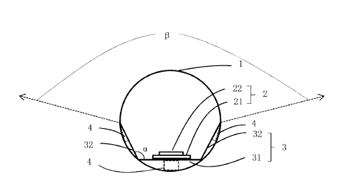
[00033] Figure 1 shows a schematic view of a lamp tube according to a first
embodiment
of the present invention. As shown in Figure 1, in the present embodiment, the
lamp tube
comprises a tube body I, light emitting member 2 and support member 3, wherein
the
support member 3 is provided with a support portion 31 and expansion portion
32, the light
emitting member 2 is located on the support portion 31 of the support member
3. The
expansion portion 32 of the support member 3 extends from one side of the
support portion
31 of the support member 3, with the light emitting member 2 installed, to the
inner wall
CA 2964650 2017-04-20
281472
of the tube body 1, at least part of the light emitted from the light emitting
member 2 is
emitted outside the tube body 1 along the expansion portion 32.
[00034] Optionally, the light emitting member 2 comprises a PCB substrate 21
and an LED
22 configured on top of the substrate.
[00035] Optionally, a light-diffusing material is applied to the inside of the
tube body 1 of
the lamp tube, the light emitted by light emitting member 2 is evenly mixed
through the
reflection from the light2diffusing material inside tube body 1, thereby
allowing better
uniformity of the light emitted by the lamp tube.
[00036] Continuing with Figure 1, in the present embodiment, the support
member 3 is at
least partially a non-diffuse reflector or a diffuse reflector. The angle
formed between the
support portion 31 and the expansion portion 32 of the support member 3 is a,
where 90
< a < 180 . As shown in Figure 1, in the present embodiment, the partial light
emitted
from the light emitting member 2 is reflected by the expansion portion 32
and/or the
support portion 31, the light emitting angle 13 of the lamp tube is less than
200 degrees.
When a gradually increases from 90 , the light emitting angle 13 of the lamp
tube also
increases. In general, in the existing designs, the light emitting element of
the lamp tube is
directly secured to the inner wall of the tube body through the use of an
adhesive, that is,
the light emitting member and the inner wall of the tube body are too close to
each other,
and the light emitting angle 13 is able to exceed 200 . In addition, traces of
the adhesive can
be seen on the side or back of the lamp tube, making it unsightly. In the
present
embodiment, in order to realize a narrower light emitting angle, the light
emitting element
2 is provided on the support portion 31 of the support member 3. At least part
of the light
emitted from the light emitting member 2 is emitted outside the tube body 1
along the
expansion portion 32. Compared with existing technology in which the light
emitting
member is directly located inside the lamp tube, the lamp tube of the present
invention can
achieve a smaller light emitting angle that improves the illumination
concentration of the
lamp tube.
6
CA 2964650 2017-04-20
281472
[00037] Optionally, the support portion 31 of the support member 3 can be a
planar, a
curved surface or other shapes capable of supporting the light emitting
member.
[00038] The support member 3 comprises a heat dissipation material which can
dissipate
the heat of the lamp. In order to facilitate the manufacturing and
installation of the lamp
tube, support member 3 is usually formed integrally with aluminum foil.
Optionally, it may
also be made of other materials with heat dissipation properties, such as
metals. In addition,
the support member 3 may also be made of other non-heat-dissipating materials
such as
plastic, resin, etc. It is possible to provide a heat dissipation coating or a
heat dissipation
film on the support member 3 made of a non-heat-dissipating material in order
to achieve
heat dissipation for the lamp tube according to actual needs.
[00039] Referring again to Figure 1, in the present embodiment, a stabilizing
portion 4 to
provide further support to the support member 3 is provided between the inner
wall of the
tube body 1 and the support member 3. The stabilizing portion 4 may be
provided between
the support portion 31 of the support member 3 and the inner wall of the tube
body I, or it
may be provided between the expansion portion 32 of the support member 3 and
the inner
wall of the tube body 1. The stabilizing portion 4 may also be integral with
the support
member 3, or it may be a separate member.
[00040] As shown in Figure 2, the lamp tube of the present invention may
further comprise
an end cap 6, whereby it is fixed by the support member 3 through the end cap
6 inside the
tube body 1. In the present embodiment, the end cap 6 is provided with one or
more
engaging portions 5, and -the support member 3 is fixed inside the tube body 1
by one or
more engaging portions 5.
[00041] As shown in Figure 3, in one embodiment, the engaging portion 5 may be
configured as a U-shaped groove. The edges of the support portion 31 and/or
expansion
portion 32 of the support member 3 are engaged inside the U-shaped engaging
portion 5,
thereby, connecting the support member 3 to inside the tube body 1 through the
U-shaped
engaging portion 5 of the end cap 6. Furthermore, the inner edge of the end
cap 6 can be
7
CA 2964650 2017-04-20
281472
securely connected to the outer edge of the tube body 1 using an adhesive, so
that the
support member 3 is even more securely fixed within the tube body I.
[00042] Although the engaging portion 5 disclosed in the present embodiment is
U-shaped,
it is to be understood that the U-shaped engaging portion 5 may also be
configured as other
similar shapes capable of functioning similarly.
[00043] As shown in Figure 4, in another embodiment, the engaging portion 5
may also
be configured as a hook, wherein the support member 3 may also work together
with the
hook to connect the engaging portion 5 to the stopper portion of the support
member 3 (not
shown in the figure). The stopper portion may be provided on the support
portion 31 and/or
the expansion portion 32 of the support member 3. The hook is connected to the
stopper
portion to secure support member 3. In particular, the hook and the stopper
portion are
engaged with each other so as to secure the support member 3 inside the tube
body I. The
stopper portion can be constructed in a variety of forms, such as projections,
recesses or
small holes.
[00044] In order to facilitate the securing, mounting and manufacturing of the
support
member 3, in the present embodiment, the support member 3 can be directly
placed inside
the tube body 1, where the support member 3 and the inner wall of the tube
body are in
linear contact. Optionally, the support member may also be secured within the
tube body
by means of an adhesive, when not considering aesthetics or when there are
other means
to apply the adhesive without it being observable from the outside of the lamp
tube.
[00045] Referring again to Figure I, both ends of the expansion portion 32 of
the support
member 3 may both be in contact with the inner wall of the tube body 1, i.e.
support
member 3 and tube body 1 are in linear contact. Optionally, as shown in
Figures 6 and 7,
the expansion portion 32 of the support member 3 may also have only one end in
contact
with the inner wall of the tube body 1, that is, the support portion 31 of the
support member
3 and the inner wall of tube body 1 are in linear contact. Optionally, the
support member 3
may not be in contact with the inner wall of the tube body 1, but may be fixed
in the tube
body 1 by an end cap, or may be fixed inside the tube body 1 by an adhesive.
8
CA 2964650 2017-04-20
281472
[00046] Figure 5 is a schematic view of an exemplary lamp tube according to a
second
embodiment of the present invention. The lamp tube of the second embodiment
shown in
Figure 5 is similar to the first embodiment as shown in Figure 1, in principle
and structure.
The difference is that in the second embodiment, the support member 3 has a
curved cross
section, with the support portion 31 and the expansion portion 32 of the
support member 3
the curved bottom portion and a segment of both sides, respectively. In order
to facilitate
the securing, mounting and manufacturing of the support member 3, in the
present
embodiment, the support member 3 can be directly placed inside the tube body
1, and the
support member 3 and the inner wall of the tube body are in linear contact.
Optionally,
support member 3 may also be secured within the tube body I by an adhesive.
[00047] As shown in Figure 5, one end of the expansion portion 32 of the
support member
3 and the inner wall of tube body I are in linear contact. Optionally, as
shown in Figure 8,
the support member 3 may not be in contact with the inner wall of the tube
body 1, but is
fixed to the tube body I only by the end cap 6 or fixed to inside the tube
body 1 by an
adhesive.
[00048] Although the cross-sectional shape of the support member 3 disclosed
in the
embodiments of the present invention may be trapezoidal or curved, it should
be
understood that shapes similar to the cross section of support member 3 may
also comprise
a concave structure and other shapes, in addition to the two mentioned above.
[00049] In the embodiment of the present invention, the support member 3 has
an
expansion portion 32 extending from one side of the support portion 31, with
the light
emitting member 2 installed to the inner wall of the tube body 1, and part of
the light from
the light emitting member 2 provided on the support member 3 emitted outside
the lamp
tube along the expansion portion 31. Therefore, the support member 3 not only
supports
the light emitting member 2, but it also acts as a light reflector and/or
collimator. Since the
lamp tube is provided with a support member 3 that comprises an expansion
portion 32, it
can thereby optimize light distribution and achieve control of the light
emitting angle.
9
CA 2964650 2017-04-20
281472 =
[00050] While there have been described herein what are considered to be
preferred and
exemplary embodiments of the present invention, other modifications of these
embodiments falling within the scope of the invention described herein shall
be apparent
to those skilled in the art.
=