Language selection

Search

Patent 2964705 Summary

Third-party information liability

Some of the information on this Web page has been provided by external sources. The Government of Canada is not responsible for the accuracy, reliability or currency of the information supplied by external sources. Users wishing to rely upon this information should consult directly with the source of the information. Content provided by external sources is not subject to official languages, privacy and accessibility requirements.

Claims and Abstract availability

Any discrepancies in the text and image of the Claims and Abstract are due to differing posting times. Text of the Claims and Abstract are posted:

  • At the time the application is open to public inspection;
  • At the time of issue of the patent (grant).
(12) Patent: (11) CA 2964705
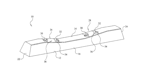
(54) English Title: RAIL SEAT CROWN AND CONCRETE RAILROAD TIE HAVING THE SAME
(54) French Title: COURONNE DE SIEGE DE RAIL ET ATTACHE DE CHEMIN DE FER EN BETON COMPORTANT LADITE COURONNE
Status: Granted
Bibliographic Data
(51) International Patent Classification (IPC):
  • E01B 3/28 (2006.01)
(72) Inventors :
  • MARTIN, JOHN K. (Canada)
(73) Owners :
  • MARTIN, JOHN K. (Canada)
(71) Applicants :
  • MARTIN, JOHN K. (Canada)
(74) Agent: CASSAN MACLEAN IP AGENCY INC.
(74) Associate agent:
(45) Issued: 2018-10-16
(22) Filed Date: 2017-04-20
(41) Open to Public Inspection: 2018-08-06
Examination requested: 2018-06-05
Availability of licence: N/A
(25) Language of filing: English

Patent Cooperation Treaty (PCT): No

(30) Application Priority Data:
Application No. Country/Territory Date
15/459,279 United States of America 2017-03-15

Abstracts

English Abstract

A concrete rail tie has an elongated tie body made of a first concrete material. The elongated tie body has an elongated top surface having a shaped profile. A preformed rail seat crown made of a second concrete material is embedded in the elongated tie body and disposed at a rail seat location of the elongated tie body. The preformed rail seat crown has top side flush with and shaped to match the shaped profile of the elongated top surface of the elongated tie body. And the second concrete material has a greater compressive strength and a greater flexural strength than the first concrete material.


French Abstract

Une attache de rail en béton comporte un corps dattache allongé fait dun premier matériau de béton. Le corps dattache allongé comporte une surface de dessus allongée ayant un profil formé. Une couronne de siège de rail préformée faite dun deuxième matériau de béton est intégrée dans le corps dattache allongé et disposée à un emplacement de siège de rail du corps dattache allongé. La couronne de siège de rail allongée a un côté supérieur affleurant et est formée pour correspondre au profil formé de la surface supérieure allongée du corps dattache allongé. Et le deuxième matériau de béton a une force de compression supérieure et une force de flexion supérieure à celles du premier matériel de béton.

Claims

Note: Claims are shown in the official language in which they were submitted.


CLAIMS:

1. A concrete rail tie comprising:
an elongated tie body made of a first concrete material, said elongated tie
body having an
elongated top surface having a shaped profile;
a preformed rail seat crown made of a second concrete material, said preformed
rail seat
crown embedded in said elongated tie body and disposed at a rail seat location
of said elongated
tie body, said preformed mil seat crown having top side flush with and shaped
to match said
shaped profile of said elongated top surface of said elongated tie body;
wherein said second concrete material has a greater compressive strength and a
greater
flexural strength than said first concrete material; and
wherein the compressive strength of the first concrete material is between 15
and 50
MPa, wherein the flexural strength of the first concrete material is between 3
and 7MPa, wherein
the compressive strength of the second concrete material is between 100 and
150 MPa, and
wherein the flexural strength of the second concrete material is between 20
and 50 MPa.
2. The concrete rail tie of claim 1, wherein said preformed rail seat crown
has a pair of
opposite lateral edges each having a notch in which is disposed a rail clip
shoulder of said
elongated tie body.
3. The concrete rail tie of claim 1, wherein said second concrete material
is reinforced by
metal fibers.
4. The concrete rail tie of claim 3, wherein said metal fibers are
stainless steel metal
fibers.
5. The concrete rail tie of claim 1, wherein said first concrete material
is prestressed
concrete.

8


6. The concrete rail tie of claim 1, wherein said preformed rail seat crown
further
includes a concaved shaped bottom side.
7. A concrete rail tie comprising:
an elongated tie body made o f a first concrete material, said elongated tie
body having an
elongated top surface having a shaped profile;
a preformed rail seat crown made of a second concrete material, said preformed
rail seat
crown embedded in said elongated tie body and disposed at a rail seat location
of said elongated
tie body, said preformed rail seat crown having top side flush with and shaped
to match said
shaped profile of said elongated top surface of said elongated tie body, said
preformed rail seat
crown having a pair of opposite lateral edges each having a notch in which is
disposed a rail clip
shoulder of said elongated tie body;
wherein said second concrete material has a greater compressive strength and a
greater
flexural strength than said first concrete material; and
wherein said second concrete material is reinforced by metal fibers;
wherein the compressive strength of the first concrete material is between 15
and 50
MPa, wherein the flexural strength of the first concrete material is between 3
and 7MPa, wherein
the compressive strength of the second concrete material is between 100 and
150 MPa, and
wherein the flexural strength of the second concrete material is between 20
and 50 MPa.
8. The concrete rail tie of claim 7, wherein said metal fibers are
stainless steel metal
fibers.
9. The concrete rail tie of claim 7, wherein said first concrete material
is prestressed
concrete.

9


10. The concrete
rail tie of claim 7, wherein said preformed rail seat crown is entirely
made of said second material.


Description

Note: Descriptions are shown in the official language in which they were submitted.


CA 2964705 2017-04-20
RAIL SEAT CROWN AND CONCRETE RAILROAD TIE HAVING THE SAME
BACKGROUND OF THE INVENTION
Field of the Invention
[001] The present invention relates generally to railroad ties, and more
particularly,
relating to prestressed concrete railroad rail ties having a rail seat capable
of
reducing rail seat damage.
Description of the Related Art
[002] Prestressed concrete railroad ties have a problem of flexural
cracking at the rail
seat, which is caused by rail seat impact loading. One solution to prevent or
reduce impact loading is to position a seat pad between the rail and the real
seat of
the tie to attenuate the impact loads and vibrations resulting from the
passage of
railroad vehicles over the rail. When the wheels pass over the tie, the seat
pad is
momentarily compressed to attenuate the load. In heavy haul situations, the
repeated cycle of compression and release of downward pressure on the seat pad

abrades the rail seat of the tie and overtime creates an undesirable void
under the
pad and rail, which is commonly referred to as rail seat abrasion.
[003] To repair rail seat abrasion, the track structure must be taken out
of service so that
the rail pad can be replaced with a thicker pad to compensate for the loss of
cement and restore the track to the proper gauge. This is process is repeated
ever
three to five years to achieve maximum tie life expectancy of about twenty-
five
years. Replacing seat pads due to rail seat abrasion is very time consuming
and

CA 2964705 2017-04-20
results in downtime and loss of revenue for the railroads when the track is
out of
service.
SUMMARY OF THE INVENTION
[004] Embodiments of the present invention overcome the problem of rail seat
abrasion
by providing a rail seat crown that is capable of resisting rail seat
abrasion.
[005] Embodiments of the present invention overcome the problem of rail seat
abrasion
by providing a concrete rail tie having a preformed rail seat crown embedded
in a
concrete rail tie.
[006] In general, in one aspect, a preformed rail seat crown to be cast
integral with a
concrete rail tie is provided. The preformed rail seat crown has top side that
is
shaped to match the profile of a top surface of a concrete rail tie and the
preformed rail seat crown made entirely of metal fiber-reinforced concrete.
[007] In general, in another aspect, a concrete rail tie is provided. The
concrete rail tie
has an elongated tie body made of a first concrete material. The elongated tie

body has an elongated top surface having a shaped profile. A preformed rail
seat
crown made of a second concrete material is embedded in the elongated tie body

and disposed at a rail seat location of the elongated tie body. The preformed
rail
seat crown has top side flush with and shaped to match the shaped profile of
the
elongated top surface of the elongated tie body. And the second concrete
material
2

CA 2964705 2017-04-20
has a greater compressive strength and a greater flexural strength than the
first
concrete material.
[008] There has thus been outlined, rather broadly, the more important
features of the
invention in order that the detailed description thereof that follows may be
better
understood and in order that the present contribution to the art may be better

appreciated.
BRIEF DESCRIPTION OF THE DRAWINGS
[009] In the drawings:
[010] Figure 1 is a perspective view of a concrete rail tie constructed in
accordance with
the principles of an embodiment of the present invention;
[011] Figure 2 is a partial top plan view of the concrete rail tie of FIG.
1;
[012] Figure 3 is a partial side elevational view of the concrete rail tie
of FIG. 1;
[013] Figure 4 is a cross-section view taken along line 4-4 in FIG. 3;
[014] Figure 5 is a cross-section view taken along line 5-5 in FIG. 2;
3

CA 2964705 2017-04-20
[015] Figure 6 is a top perspective view of a preformed rail seat crown
construction in
accordance with the principles of an embodiment of the present invention;
[016] Figure 7 is a bottom perspective view of the preformed rail seat
crown of FIG. 6;
[017] Figure 8 is a top perspective view of a preformed rail seat crown
construction in
accordance with the principles of an embodiment of the present invention; and
[018] Figure 9 is a bottom perspective view of the preformed rail seat
crown of FIG. 8.
DETAILED DESCRIPTION OF THE INVENTION
[019] FIGS. 1 through 5 illustrate a new concrete railroad tie 10 in
accordance with an
embodiment of the present invention. The tie 10 includes an elongated tie body
12
defined by an elongated top surface 14, a pair of opposing elongated side
surfaces
16 and 18, an elongated bottom surface 20, and a pair of opposing end surfaces
22
and 24 connecting the lateral edges of the top, side, and bottom surfaces.
[020] The tie body 12 has generally a trapezoidal cross-section such that
at any point
along the length of the tie body, the width of the top surface 14 is lesser
than that
of the bottom surface 20. The tie body 12 is made of a concrete material,
preferably prestressed concrete.
[021] The tie body 12 includes a pair of rail seat sections 26 and 28 that
are laterally
spaced along the length of the tie body. Each rail seat section includes a
pair of
4

CA 2964705 2017-04-20
rail clip shoulders 30 and 32 that laterally spaced and disposed on opposite
sides
of the rail seat section. The rail clip shoulders are embedded into the tie
body 12
and are adapted to removably receive rail clips to hold a rail in position on
the rail
seat section.
[022] The tie 10 further includes a rail seat crown 34 located at each rail
seat section 26
and 28. The rail seat crown 34 is preformed and embedded into the tie body 12
during casting and is disposed between the rail clip shoulders 30 and 32. In
the
depicted embodiment, the top side 36 of the rail seat crown 34 is flush with
the
top surface 14 of the tie body 12. Additionally, in the depicted embodiment,
the
top side 36 of the rail seat crown 34 is shaped to match the profile of the
top
surface 14 of the tie body 12. In other embodiments, depending upon the
application, it may be desirable for the top side 36 of the rail seat crown 34
to be
shaped differently from the profile of the top surface 14 of the tie body 12.
[023] The rail seat crown 34 further includes a bottom side 38 that is
opposite of the top
side 36 and is flat surface. The rail seat crown 34 further includes a pair of

opposite lateral edges 40 and 42 each having a notch 44 in which is disposed a
rail
clip shoulder 30 and 32, respectively, of said elongated tie body 12. The
engagement between the rail clip shoulders 30 and 32 and notch 44 of each
lateral
edge 40 and 42 hold the rail seat crown 34 in position and prevents lateral
movement of the rail seat crown.

CA 2964705 2017-04-20
[024] The rail seat crown 34 is made of a different material from the
material that the tie
body is constructed. Particularly, the rail seat crown 34 is made of a
material that
has a higher compressive strength and flexural strength than that of the
material
forming the tie body. For example, the compressive strength of the material
forming the tie body may be between 15 to 50 MPa, whereas the compressive
strength of the material forming the rail seat crown 34 may be between 100 and

150 MPa. Addition, the flexural strength of the material forming the tie body
may
be between 3 and 7 MPa, whereas the flexural strength of the material forming
the
seat crown 34 may be between 20 and 50 MPa. Further, the material forming the
rail seat crown 34 may be reinforced by metal fiber or other fibers material.
In an
embodiment, the metal fiber may be stainless steel metal fiber. A suitable
material
for the rail seat crown is described in U.S. Patent Numbers 8,303,708;
6,887,309;
6,478,867 or 6,723,162.
[025] In FIGS. 6 and 7, the rail seat crown 34 is shown separate from the
rail tie 10 and
illustrates the top side 36, the bottom side 38, the lateral edges 40 and 42,
and the
notch 44 formed through each lateral edge.
[026] The rail seat crown 34 is preformed prior to casting the rail tie
body 12 and is
placed into the mold used to cast the rail tie body 12, such that the rail
seat crown
is embedded into the rail tie body in the manner described above. In
application,
the preformed rail seat crown 34 prevents rail seat abrasion caused by the
cyclic
6

CA 2964705 2017-04-20
compression and release of the rail seat pad disposed between the rail and the
top
surface 36 of the rail seat crown.
[027] In FIGS. 8 and 9, there is representatively illustrated a rail seat
crown 34'
according to a second embodiment. Rail seat crown 34' is substantially similar
to
rail seat crown 34 except bottom side 38' is concaved shape. The bottom side
38'
being concaved allows for the rail seat crown 34' to be more securely embedded

within the rail tie body 12. That is, the concaved shape of the bottom side
38'
prevents the rail seat crown 34' from shifting relative the rail tie body 12,
that
otherwise may happen with a flat bottom side.
7

Representative Drawing
A single figure which represents the drawing illustrating the invention.
Administrative Status

For a clearer understanding of the status of the application/patent presented on this page, the site Disclaimer , as well as the definitions for Patent , Administrative Status , Maintenance Fee  and Payment History  should be consulted.

Administrative Status

Title Date
Forecasted Issue Date 2018-10-16
(22) Filed 2017-04-20
Examination Requested 2018-06-05
(41) Open to Public Inspection 2018-08-06
(45) Issued 2018-10-16

Abandonment History

There is no abandonment history.

Maintenance Fee

Last Payment of $100.00 was received on 2024-04-10


 Upcoming maintenance fee amounts

Description Date Amount
Next Payment if small entity fee 2025-04-22 $100.00
Next Payment if standard fee 2025-04-22 $277.00

Note : If the full payment has not been received on or before the date indicated, a further fee may be required which may be one of the following

  • the reinstatement fee;
  • the late payment fee; or
  • additional fee to reverse deemed expiry.

Patent fees are adjusted on the 1st of January every year. The amounts above are the current amounts if received by December 31 of the current year.
Please refer to the CIPO Patent Fees web page to see all current fee amounts.

Payment History

Fee Type Anniversary Year Due Date Amount Paid Paid Date
Application Fee $200.00 2017-04-20
Request for Examination $400.00 2018-06-05
Final Fee $150.00 2018-09-06
Maintenance Fee - Patent - New Act 2 2019-04-23 $50.00 2019-03-26
Maintenance Fee - Patent - New Act 3 2020-04-20 $50.00 2020-03-27
Maintenance Fee - Patent - New Act 4 2021-04-20 $50.00 2021-03-11
Maintenance Fee - Patent - New Act 5 2022-04-20 $100.00 2022-04-13
Maintenance Fee - Patent - New Act 6 2023-04-20 $100.00 2023-04-03
Maintenance Fee - Patent - New Act 7 2024-04-22 $100.00 2024-04-10
Owners on Record

Note: Records showing the ownership history in alphabetical order.

Current Owners on Record
MARTIN, JOHN K.
Past Owners on Record
None
Past Owners that do not appear in the "Owners on Record" listing will appear in other documentation within the application.
Documents

To view selected files, please enter reCAPTCHA code :


To view images, click a link in the Document Description column. To download the documents, select one or more checkboxes in the first column and then click the "Download Selected in PDF format (Zip Archive)" or the "Download Selected as Single PDF" button.

List of published and non-published patent-specific documents on the CPD .

If you have any difficulty accessing content, you can call the Client Service Centre at 1-866-997-1936 or send them an e-mail at CIPO Client Service Centre.


Document
Description 
Date
(yyyy-mm-dd) 
Number of pages   Size of Image (KB) 
Maintenance Fee Payment 2020-03-27 1 19
Maintenance Fee Payment 2021-03-11 1 19
Office Letter 2022-04-04 2 193
Maintenance Fee Payment 2022-03-28 1 20
Maintenance Fee Payment 2022-04-13 1 28
Maintenance Fee Payment 2023-04-03 1 24
PPH Request / Amendment 2018-06-06 11 355
Request for Examination 2018-06-05 1 25
Early Lay-Open Request 2018-06-05 1 26
Claims 2018-06-06 3 76
Representative Drawing 2018-07-03 1 6
Cover Page 2018-07-03 2 36
Final Fee 2018-09-06 1 26
Cover Page 2018-09-21 1 33
Maintenance Fee Payment 2019-03-26 3 122
Office Letter 2019-09-20 2 36
Maintenance Fee Payment 2024-04-10 1 25
Office Letter 2024-03-28 2 189
Abstract 2017-04-20 1 16
Description 2017-04-20 7 206
Claims 2017-04-20 3 70
Drawings 2017-04-20 5 51