Note: Descriptions are shown in the official language in which they were submitted.
CA 02964748 2017-04-13
WO 2016/080978 PCT/US2014/066349
Drilling Direction Correction of a Steerable Subterranean
Drill in view of a Detected Formation Tendency
FIELD
[0001] The present disclosure relates generally to subterranean drilling
systems. More
particularly, the present disclosure relates to adjusting drilling steering
direction in consideration
of formation tendency.
BACKGROUND
[0002] During drilling operations, there are numerous forces that act on a
drill bit that can
influence the drilling direction. For example, a drilling steering tool, such
as a rotary steerable
tool, may be impacted by lateral forces that tend to "push" steering, via the
drill bit, in a
particular direction.
[0003] Lateral forces include, for example, forces exerted on the drill bit
by the formation
through which drilling is taking place. During straight drilling, lateral
forces can result from
such causes as anomalies in the formations being drilled, formation
anisotropy, imbalances in the
drill string, the arrangement of components within the drill string, and as a
reaction to rotation of
the drill bit (also referred to colloquially as "bit walk"). During
directional drilling, lateral forces
may additionally result from reaction forces exerted by the formation in
resistance to the steering
tool's lateral push to change the direction of drilling. These lateral forces
exerted by the
formation against the drill bit, and in turn the steering tool, are referred
to generally as
"formation tendency."
[0004] Directional steering of the drill can be carried out in several
ways. For example, in
a "push the bit" system, the drill bit is pushed laterally in the desired
direction. In a "point-the-
bit" system, the drill bit is pointed in the desired direction by changing the
orientation of the drill
bit axis relative the borehole. In both systems, for steering purposes, it is
typically assumed that
drilling proceeds in the direction the drill bit is pushed or pointed, and
that the borehole exerts a
reaction force on the steering tool in a direction directly opposite to the
direction in which the
drill bit is being pushed or pointed.
[0005] However, the indeterminate lateral forces noted above push and pull
on the drill bit,
via the toolfacc, altering the steering direction and causing drilling to veer
off course. Therefore,
CA 02964748 2017-04-13
WO 2016/080978 PCMJS2014/066349
an operator may intend to drill in one direction toward a target, yet due to
these lateral forces,
drilling proceeds off course.
BRIEF DESCRIPTION OF THE DRAWINGS
[0006] Implementations of the present technology will now be described, by
way of
example only, with reference to the attached figures, wherein:
[0007] FIG. 1 is a schematic diagram illustrating vectors of the formation
tendency;
[0008] FIG. 2A is a schematic diagram illustrating vectors of the formation
tendency and a
desired drilling direction;
[0009] FIG. 2B is a schematic diagram illustrating vectors of the formation
tendency and
an actual drilling direction;
[0010] FIG. 2C is a schematic diagram illustrating vectors of the formation
tendency and a
corrected drilling direction;
[0011] FIG. 3 is a schematic diagram illustrating vectors of the formation
tendency and a
desired drilling direction;
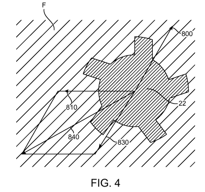
[0012] FIG. 4 is an exemplary sectional view demonstrating a simplified
vector calculation
for correcting drilling direction;
[0013] FIG. 5 is a diagram illustrating one example of a 360 degree sweep
by the toolface
of a drill bit;
[0014] FIG. 6A is a diagram illustrating an embodiment of a rotary
steerable drilling
device;
[0015] FIG. 6B is a diagram illustrating an embodiment of a rotary
steerable drilling
device;
[0016] FIG. 7 is a diagram illustrating a drilling shaft deflection
assembly, including a
rotatable outer eccentric ring and a rotatable inner eccentric ring;
[0017] FIG. 8 is a diagram illustrating an embodiment of a deflection
assembly of the
drilling shaft deflection assembly that exaggerates the offset position of the
drilling shaft relative
the housing;
[0018] FIG. 9 is a schematic diagram illustrating an embodiment of an
internal portion of a
drilling shaft deflection device having a pair of drive motors;
[0019] FIG. 10 is a schematic diagram illustrating a portion of a rotary
steerable drilling
2
CA 02964748 2017-04-13
WO 2016/080978 PCMJS2014/066349
device with hatch covers removed and the pair of drive motors and
transmissions exposed;
[0020] FIG. 11 is a schematic diagram illustrating an embodiment of a
simplified
electrically commutated motor;
[0021] FIG. 12 is a diagrammatic flowchart for correcting the drilling
direction based on a
detected formation tendency;
[0022] FIG. 13 is a diagram illustrating an exemplary rotary steerable
device with sensors
for measuring formation tendency;
[0023] FIG. 14A is a diagram illustrating exemplary eccentric rings
configured such that
the thick side of the inner ring is oriented with the thin side of the outer
ring thereby centering
the drilling shaft with respect to the assembly;
[0024] FIG. 14B is a diagram illustrating exemplary eccentric rings
configured such that
the thick side of the inner ring is oriented with the thick side of the outer
ring thereby deflecting
the drilling shaft with respect to the assembly;
[0025] FIG. 15A is a diagram illustrating zero deflection of the drilling
shaft with the
eccentric rings configured as in FIG. 14A;
[0026] FIG. 15B is a diagram illustrating an exemplary deflected drilling
shaft with the
eccentric rings configured as in FIG. 14B;
[0027] FIG. 16A is an exemplary sectional view illustrating complementary
ramps with
the housing shifted to the left such that the drilling shaft is in an
undeflected configuration;
[0028] FIG. 16B is an exemplary sectional view illustrating complementary
ramps with
the housing shifted to the right such that the drilling shaft is in a
deflected configuration;
[0029] FIG. 17A is an exemplary sectional view illustrating a "push-the-
bit" system
wherein the hydraulic pads extend uniformly within the borehole;
[0030] FIG. 17B is an exemplary sectional view illustrating a "push-the-
bit" system
wherein the hydraulic pads extend non-uniformly within the borehole;
[0031] FIG. 18 an exemplary sectional view illustrating component forces of
a formation
force acting on hydraulic pads of a "push-the-bit" system; and
[0032] FIG. 19 a schematic view illustrating vector calculation in view of
the forces acting
on the hydraulic pads of a "push-the-bit" system in FIG. 16.
[0033] FIG. 20 is a diagram illustrating an embodiment of a drilling rig
for drilling a
borehole with the drilling system in accordance with the principles of the
present disclosure;
3
CA 02964748 2017-04-13
WO 2016/080978 PCMJS2014/066349
DETAILED DESCRIPTION
[0034] It will be appreciated that for simplicity and clarity of
illustration, where
appropriate, reference numerals have been repeated among the different figures
to indicate
corresponding or analogous elements. In addition, numerous specific details
are set forth in
order to provide a thorough understanding of the embodiments described herein.
However, it
will be understood by those of ordinary skill in the art that the embodiments
described herein can
be practiced without these specific details. In other instances, methods,
procedures and
components have not been described in detail so as not to obscure the related
relevant feature
being described. Also, the description is not to be considered as limiting the
scope of the
embodiments described herein. The drawings are not necessarily to scale and
the proportions of
certain parts have been exaggerated to better illustrate details and features
of the present
disclosure.
[0035] In the following description, terms such as "upper," "upward,"
"lower,"
"downward," "above," "below," "downhole," "uphole," "longitudinal," "lateral,"
and the like, as
used herein, shall mean in relation to the bottom or furthest extent of, the
surrounding borehole
even though the borehole or portions of it may be deviated or horizontal.
Correspondingly, the
transverse, axial, lateral, longitudinal, radial, and the like orientations
shall mean positions
relative to the orientation of the borehole or tool. Additionally, the
illustrated embodiments are
depicted so that the orientation is such that the right-hand side is downhole
compared to the left-
hand side.
[0036] Several definitions that apply throughout this disclosure will now
be presented.
The term "coupled" is defined as connected, whether directly or indirectly
through intervening
components, and is not necessarily limited to physical connections. The
connection can be such
that the objects are permanently connected or releasably connected. The term
"communicatively
coupled" is defined as connected, either directly or indirectly through
intervening components,
and the connections are not necessarily limited to physical connections, but
are connections that
accommodate the transfer of data between the so-described components. The term
"outside"
refers to a region that is beyond the outermost confines of a physical object.
The term "inside"
indicates that at least a portion of a region is partially contained within a
boundary formed by the
object. The term "substantially" is defined to be essentially conforming to
the particular
dimension, shape or other thing that "substantially" modifies, such that the
component need not
4
CA 02964748 2017-04-13
WO 2016/080978 PCMJS2014/066349
be exact. For example, substantially cylindrical means that the object
resembles a cylinder, but
can have one or more deviations from a true cylinder.
[0037] The term "radial" and/or "radially" means substantially in a
direction along a radius
of the object, or having a directional component in a direction along a radius
of the object, even
if the object is not exactly circular or cylindrical. The term "axially" means
substantially along a
direction of the axis of the object. If not specified, the term axially is
such that it refers to the
longer axis of the object.
[0038] A system and method are disclosed for correcting a drilling
direction of a steerable
subterranean drill in consideration of a contemporaneously detected formation
tendency force
acting on a drill bit. In particular, the direction and magnitude of a
formation tendency force
acting on the drill bit of the steerable subterranean drill is first detected.
The steering direction
setting device is then configured to contemporaneously cause the drill bit of
the steerable
subterranean drill to drill in the desired direction, counteracting the
formation tendency force
based on the detected direction and magnitude of the formation tendency force
acting on the drill
bit.
[0039] As disclosed herein, the direction and magnitude of the formation
tendency may be
detected by sweeping a drill bit in a substantially 360 degree orbit. By
measuring the peak
maximum torque during this sweep, as well as the orientation at which it
occurs, the direction
and magnitude of the formation tendency can be determined. Additionally the
steering direction
setting device can include electrically commutated motors (ECM) and eccentric
rings to carry
out the sweep as well as effect direction. The current supplied to the ECM
during the sweep can
provide a basis for calculating torque, and consequently, the magnitude of the
formation
tendency. A controller can then transmit instructions to correct the drilling
direction to
counteract the effects of formation tendency.
Steering Corrections based on
Forces Acting on a Steering Tool
[0040] During drill operations, there are numerous forces that act on a
drill bit which can
influence the drilling direction, such as formation anisotropy, and various
anomalies in the
formation. These forces imposed by the formation, referred to herein for
convenience as
formation tendency, can cause the drilling direction to veer off course from
the desired direction.
There may be a number of formation forces acting at any one location, but
those forces can be
CA 02964748 2017-04-13
WO 2016/080978 PCT/1JS2014/066349
resolved into one resultant formation force. The component of the formation
force (tendency)
that is aligned with the drilling direction imposes little effect on drilling
direction, but the
transverse component of the resultant formation force can cause drilling
direction deviation.
Therefore, the forces acting on the drill bit and/or tool face are frequently
referred to as lateral
force(s). Because of these course-altering formation forces, the drilling
operator must repeatedly
check-and-correct the drilling direction of the drill bit in an on-going,
iterative process. The
present disclosure, however, describes a proactive process in which the
formation tendency is
detected and the drilling direction contemporaneous adjusted to compensate for
the formation
tendency in order to achieve the desired drilling direction. Contemporaneous
herein means a real
time response, where drilling direction is substantially immediately or
concurrently adjusted, or
at approximately the same time so as to correct for the effect of formation
tendency on drilling
direction.
[0041] One example of the effect of lateral forces, such as formation
tendency is illustrated
in FIG. 1. Shown in FIG. 1 is a drill shaft 24 having drill bit 22, which is
drilling down within a
formation F. The formation F is made up of a plurality of layers 5 stacked
upon one another and
extending in varying directions. The formation layers 5 can be the same or
different type of rock
but will differ by some property or characteristic which differentiates one
layer from another.
When drilling, the shape and slope of each of the layers can affect the
direction of drilling. The
change in direction imposed on the drilling direction by the shape of these
layers can be referred
to as formation tendency discussed above. As shown in FIG. 1, the drill bit 22
begins to drill
into the surface 9 of a new layer of rock in formation F. The formation layer
imposes a force on
the drill bit with a magnitude and direction (i.e., vector) illustrated by the
respective vector
arrows in FIG. 1. The layer imposes a side force illustrated by vector 6, as
well as a vertical
force illustrated by vector 8 on the drill bit 22. From these, a formation
tendency normal force
illustrated by vector 7 is imposed on the drill bit 22 as shown in FIG. 1.
[0042] The same vertical force vector 8, side force vector 6, and formation
tendency
normal force vector 7 are shown also in FIG. 2A (vectors, i.e., direction and
magnitude of a
forces, are represented by the arrows in FIGS. 2A-2C). The forces are shown in
an isometric
view of drill shaft 24 and drill bit 22. The desired drilling direction vector
810 shown by the
arrow pointing to the upper left of the figure indicates the desired drilling
direction. Due to the
formation tendency normal force represented by vector 7 on the drill bit 22,
the drilling direction
6
CA 02964748 2017-04-13
WO 2016/080978 PCT/US2014/066349
is shifted off course from desired drilling direction represented by vector
810. In particular, as
shown in FIG. 2B, the side force represented by vector 6 shifts drilling from
the desired direction
shown by vector 810 to the actual drilling direction represented by vector
820. In this way the
direction of drilling is shifted off course. However, as described herein, by
applying vector
addition, a corrective force can be applied to counteract the force imposed by
the formation
tendency. In particular, by vector addition, in view of the side force vector
6 and the desired
drilling direction vector 810, the corrected drilling direction vector 840 can
be determined,
represented by the arrow pointing downward and to the left in FIG. 2C.
Accordingly, by drilling
in this corrected direction, the formation tendency can be counteracted and
drilling in the desired
direction 810 can be achieved.
[0043] An additional schematic discussion is illustrated in FIGS. 3-4,
showing a sectional
view of formation F and a drilling bit 22. Illustrated in FIG. 3 is a vector
arrow 800 pointing to
the upper right of the figure which represents the direction and magnitude of
the force of the
formation tendency. The vector 810 pointing to the left side of the figure
represents the desired
drilling direction and magnitude. The magnitude of the desired direction can
be referred to for
example as the side cutting force ¨ due to the drill bit cutting, or being
forced, diagonally into the
formation as it drills. Such value can be measured by a force sensor, and/or
by the MWD system
previously noted. Alternatively, or additionally, this can be determined with
reference to the
amount of pressure applied at the surface upon the drill string in the
borehole. Depending on the
magnitude and direction of the formation tendency, the actual drilling
direction will proceed
somewhere between the desired drilling direction and the direction of the
formation tendency.
[0044] With knowledge of the magnitude and direction at which the formation
is exerting
force, the desired drilling direction can be instituted. For example, by
employing simple vector
mathematics, the force of the formation tendency can be accounted for, and the
desired drilling
direction achieved. For example, FIG. 4 demonstrates a simple vector addition.
The formation
tendency is shown by the vector arrow 800 pointing to the upper right, whereas
the desired
drilling direction is shown by the vector 810 pointing to the left similar to
FIG. 3. By noting a
counteracting force (equal, but opposite) 830 to the formation force, along
with the desired
drilling direction and magnitude of vector 810, a resulting vector 840 can be
determined. This
resultant vector 840 represents the force and direction at which the toolface
must act on the
7
CA 02964748 2017-04-13
WO 2016/080978 PCMJS2014/066349
formation during drilling in order to overcome the formation tendency and
drill in the desired
direction.
[0045] The magnitude and direction of the formation tendency is determined
empirically,
and can differ greatly between sites and along a formation borehole. Disclosed
herein are
multiple examples for measuring or determining the formation tendency.
[0046] In some examples, the direction and magnitude of the formation
tendency can be
determined by using a rotary steerable drilling device. For example, referring
to FIG. 5, the
formation tendency is determined by rotating a deflected drilling shaft 24
through a substantially
360 degree sweep during which the toolface of the drill bit 22 is pressed
against the
circumferential periphery of the borehole wall. In the absence of any lateral
force, such as
formation tendency, the force required to rotate the toolface in one complete
revolution will be
constant throughout the sweep. However, if the formation imposes a lateral
force, the portion of
the sweep which acts opposite the formation tendency will require the
greatest, or maximum,
torque. By measuring this peak maximum torque, as well as the orientation of
the drilling shaft
24 or drill bit 22 at which it occurred, the lateral force applied by the
formation as well as its
direction can be determined. Accordingly, both (1) the magnitude of the
maximum torque and
(2) the orientation at which maximum torque occurred is determined. Based on
this
measurement, steering corrections can be made as in FIG. 4 in order to drill
in the desired
direction.
[0047] The shaft deflection device of a rotary steerable drilling device
disclosed herein,
and discussed in detail in FIGS. 6A and 6B below, can be used to determine
formation tendency.
In particular, the torque provided by the drive motors of the shaft deflection
device for rotation
of the shaft in the rotary steerable drilling device can be used to determine
formation tendency.
Further, the torque is determinable based on built in features of an
electrically commutated motor
(ECM) as part of the drive motors.
8
CA 02964748 2017-04-13
WO 2016/080978 PCMJS2014/066349
Rotary Steering Device having a Drilling Shaft Deflection Device
[0048] As shown in FIGS. 6A and 6B, the rotary steerable drilling device 20
includes a
rotatable drilling shaft 24 which is connectable or attachable to a rotary
drilling bit 22 and to a
rotary drilling string 25 during the drilling operation. More particularly,
the drilling shaft 24 has
a proximal end 26 typically closest to the earth's surface via the wellbore 48
(shown in FIG. 20)
and a distal end 28 deepest in the well, typically furthest from the earth's
surface via the wellbore
48.
[0049] The distal end 28 of the drilling shaft 24 is drivingly connectable
or attachable with
the rotary drilling bit 22 such that rotation of the drilling shaft 24 by the
drilling string 25 results
in a corresponding rotation of the drilling bit 22.
[0050] The rotary steerable drilling device 20 includes a housing 46 for
rotatably
supporting a length of the drilling shaft 24 for rotation therein upon
rotation of the attached
drilling string 25. The housing 46 may support, and extend along any length of
the drilling shaft
24. However, in the illustrated example, the housing 46 supports substantially
the entire length of
the drilling shaft 24 and extends substantially between the proximal and
distal ends 26, 28 of the
drilling shaft 24.
[0051] An exemplary drilling shaft deflection device 750 is provided in
order to deflect the
shaft to the desired deflection (bend), obtain the desired azimuthal
orientation, as well as sweep
the drill bit 22 as shown in FIG. 5. One or more motors (two are shown)
including for example
an outer eccentric ring drive motor 760a and an inner eccentric ring drive
motor 760b received
beneath the hatches 710a, 710b are. The hatches 710a, 710b can be secured to
the housing 46
with threaded bolts or similar releasable securement mechanisms that
facilitate the hatches' 710a,
710b removal. A seal can also be provided between the hatches 710a, 710b and
the housing 46
which maintains a fluid tight, closed compartment within the housing 46.
[0052] The outer eccentric ring drive motor 760a and an inner eccentric
ring drive motor
760b are coupled indirectly to the deflection assembly 92 via fixed-ratio
transmissions
(illustrated in FIGS. 9-10). The deflection assembly 92 provides for the
controlled deflection of
the drilling shaft 24 resulting in a bend or curvature of the drilling shaft
24 in order to provide
the desired deflection of the attached drilling bit 22. The orientation of the
deflection of the
drilling shaft 24 may be altered in order to change the orientation of the
drilling bit 22 or
toolface, while the magnitude of the deflection of the drilling shaft 24 may
also be altered to vary
9
CA 02964748 2017-04-13
WO 2016/080978 PCMJS2014/066349
the magnitude of the deflection of the drilling bit 22 or the bit tilt
relative to the housing 46. As
described below the deflection assembly can include eccentric rings.
[0053] The outer eccentric ring drive motor 760a and an inner eccentric
ring drive motor
760b may be ECMs. As discussed in more detail below, the use of built in
features and
commutative information of ECMs, along with the fixed ratio coupling to the
deflection
assembly 92, permits determination of the relative orientation of the
deflection of the drilling
shaft effected by the deflection assembly 92 as well as the torque required
for rotation.
[0054] During drilling, the rotary steerable drilling device 20 is anchored
against rotation
in the wellbore by anti-rotation device 252 or any mechanism, structure,
device or method
capable of restraining or inhibiting the tendency of the housing 46 to rotate
upon rotary drilling
may be used. Advantageously, wheels resembling round pizza cutters can be
employed that
extend at least partially outside the rotary steerable drilling device 20 and
project into the earth
surrounding the borehole.
[0055] The distal end includes a distal radial bearing 82 which included a
fulcrum bearing,
also referred to as a focal bearing, or some other bearing which facilitates
the bending of the
drilling shaft 24 at the distal radial bearing location upon the controlled
deflection of the drilling
shaft 24 by the rotary steerable drilling device 20 to produce a bending or
curvature of the
drilling shaft 24.
[0056] The rotary steerable drilling device 20 has at least one proximal
radial bearing 84
which is contained within the housing 46 for rotatably supporting the drilling
shaft 24 radially.
[0057] The housing orientation sensor apparatus 364 can contain an ABI or
At-Bit-
Inclination insert associated with the housing 46. Additionally, the rotary
steerable drilling
device 20 can have a drilling string orientation sensor apparatus 376. Sensors
which can be
employed to determine orientation include for example magnetometers and
accelerometers. The
rotary steerable drilling device 20 also optionally has a releasable drilling-
shaft-to-housing
locking assembly 382 which can be used to selectively lock the drilling shaft
24 and housing 46
together.
[0058] Further, in order that information or data may be communicated along
the drilling
string 25 from or to downhole locations, the rotary steerable drilling device
20 can include a
drilling string communication system 378.
CA 02964748 2017-04-13
WO 2016/080978 PCMJS2014/066349
Deflection Mechanism
[0059] The drive motors 760a, 760b noted above are connected indirectly to
the deflection
assembly 92 by fixed-ratio transmissions 780, or transmission components for
deflection of the
drilling shaft 24. As shown in the exemplary embodiment illustrated in FIG. 7,
the deflection
assembly 92 has a deflection mechanism 384 made up of a double ring eccentric
mechanism.
The eccentric rings may be located at a spaced apart distance from one another
along the length
of the drilling shaft 24. However, in the illustrated example, the deflection
mechanism 384 is
made up of an eccentric outer ring 156 and an eccentric inner ring 158,
provided one within the
other at the same axial location or position along the drilling shaft 24,
within the housing 46.
Rotation of one or both of the two eccentric rings 156, 158 imparts a
controlled deflection of the
drilling shaft 24 at the location of the deflection mechanism 384.
[0060] The eccentric rings contain a drilling shaft receiver 27 which
receives and is
coupled about the drilling shaft 24 passing therethrough. The central axis of
the drilling shaft 24
and the drilling shaft receiver 27 substantially coincide. The outer ring 156,
and also the circular
outer peripheral surface 160 of the outer ring 156, may be rotatably supported
by or rotatably
mounted on, directly or indirectly, the circular inner peripheral surface 78
of the housing 46.
When indirectly supported, there can be included for example an intermediate
housing 751
between the outer ring 156 and inner peripheral surface 78 of the housing 46.
[0061] The circular inner peripheral surface 78 of the housing 46 is
centered on the center
of the drilling shaft 24, or the rotational axis "A" of the drilling shaft 24,
when the drilling shaft
24 is in an undeflected condition or the deflection assembly 92 is
inoperative. The circular inner
peripheral surface 162 of the outer ring 156 is centered on point "B" which is
offset from the
centerlines of the drilling shaft 24 and housing 46 by a distance "e."
[0062] The circular inner peripheral surface 168 of the inner ring 158 is
centered on point
"C", which is deviated from the center "B" of the circular inner peripheral
surface 162 of the
outer ring 156 by the same distance "e". As described, the degree of deviation
of the circular
inner peripheral surface 162 of the outer ring 156 from the housing 46,
defined by distance "e", is
substantially equal to the degree of deviation of the circular inner
peripheral surface 168 of the
inner ring 158 from the circular inner peripheral surface 162 of the outer
ring 156, also defined
by distance "e".
11
CA 02964748 2017-04-13
WO 2016/080978 PCMJS2014/066349
[0063] Upon the rotation of the inner and outer rings 158, 156, either
independently or
together, the center of the drilling shaft 24 may be moved with the center of
the circular inner
peripheral surface 168 of the inner ring 158 and positioned at any point
within a circle having a
radius equal to the sum of the amounts of deviation of the circular inner
peripheral surface 168 of
the inner ring 158 and the circular inner peripheral surface 162 of the outer
ring 156.
[0064] In other words, by rotating the inner and outer rings 158, 156
relative to each other,
the center of the circular inner peripheral surface 168 of the inner ring 158
can be moved to any
position within a circle having the predetermined or predefined radius as
described above. Thus,
the portion or section of the drilling shaft 24 extending through and
supported by the circular
inner peripheral surface 168 of the inner ring 158 can be deflected by an
amount in any direction
perpendicular to the rotational axis of the drilling shaft 24.
[0065] A simplified and exaggerated expression of the drilling shaft 24
deflection concept
is illustrated in FIG. 8. As depicted, the orientation of the rings 156, 158
causes deflection of the
drilling shaft 24 in one direction thereby tilting the drilling bit 22 in the
opposite direction
relative to the centerline of the deflector housing 46.
[0066] In practice, a control signal is sent to one or both motors 760a,
760b which then
actuates and applies a rotating force through one or both spider couplings
763a, 763b to drive the
shafts 765a, 765b that rotate their respective pinions 766a, 766b. The pinions
766a, 766b engage
and rotate their respective spur gears 770a, 770b, which communicate rotation
to the respective
eccentric rings 156, 158. In this way, the eccentric rings can be singly, or
simultaneously rotated
from a position in which the axial centers are aligned (i.e., "e" minus "e"
equals zero) to any
other desired position within a circle having a radius of "2e" around the
centerline A of the
housing 46. In this way the drilling shaft 24 is deflected at a desired angle.
That is, the amount
of deflection is affected based on how far the drilling shaft 24 is radially
displaced (pulled) away
from the centerline of the housing 46. The degree of radial displacement can
be affected by
rotation of one or both of the eccentric rings 156, 158, in either direction.
[0067] Subsequent deflection of the shaft, by rotating the eccentric rings
simultaneously,
the toolface can be swept in a 360 degree orbit as shown in FIG. 5. The torque
provided by the
drive motors for the sweep can be used to determine the peak torque during the
sweep as well as
the orientation at which it occurred, in part due to fixed-ratio transmission
between the motors
760a, 760b and the eccentric rings 156, 158.
12
CA 02964748 2017-04-13
WO 2016/080978 PCMJS2014/066349
Deflection Mechanism
[0068] As shown in FIGS. 9-10, the drive motors 760a, 760b are connected to
the
eccentric rings by fixed-ratio transmissions 780, or transmission components.
These are fixed in
their gear ratios such that upon rotation of a rotor within motors 760a, 760b
the fixed-ratio
transmissions 780 transmit the rotor's rotation to the mechanical actuator at
a particular ratio.
The transmissions include for example, spider couplings, shafts, pinions, spur
gears further
outlined and defined hereinbelow. In particular, the drive motors 760a, 760b
are each coupled to
a pinion 766a, 766b via upper spider coupling 763a and lower spider coupling
763b. The spider
couplings 763a, 763b are each comprised of opposing interlocking teeth 762a,
762b which
communicate rotation from the drive motors 760a, 760b to a set of pinions
766a, 766b. The
upper coupling portion 765a, 765b of each spider coupling 763a, 763h includes
a series of teeth
and channels that engage a similar (mirror image) series of teeth and channels
on the lower
coupling portion 764a, 764b of each spider coupling 763a, 763b. There can be
drive shafts 767a,
767b which extend from the lower coupling portion 764a, 764b to an outer
eccentric ring pinion
766a and inner eccentric ring pinion 766b. The respective pinions 766a, 766b
are each splined,
having gear teeth that engage with an outer eccentric ring spur gear 770a and
inner eccentric ring
spur gear 770b. The spur gears 770a, 770b are each splined, having gear teeth
that surround the
entire peripheral edge of the respective gear and receive the teeth from
pinions 766a, 766b. The
spur gears 770a, 770b can have substantially the same diameter, with a
circumference less than
that of the housing 46, and alternatively may also have the same or greater
than the outer
eccentric ring 156.
[0069] The pinions 766a, 766b are positioned adjacent the spur gears 770a,
770b, at their
periphery, so that pinion teeth intermesh with spur gear teeth as shown in
FIG. 9. The motors
760a, 760b provide rotational driving force that is communicated through the
spider coupling
763a, 763b and drive shafts 767a, 767b causing rotation of the pinions 766a,
766h. The rotating
pinions 766a, 766b engage and rotate the spur gears 770a, 770b. The spur gears
770a, 770b can
be connected directly or indirectly to the outer and inner eccentric rings
156, 158 contained
within the body of the deflection device 750. For example, spur gears 770a,
770b can be bolted
to inner and outer eccentric rings 156, 158. In the illustrated example, the
outer eccentric ring
spur gear 770a is coupled to the outer eccentric ring 156 via a linkage, which
may take the form
13
CA 02964748 2017-04-13
WO 2016/080978 PCMJS2014/066349
or an interconnected cylindrical sleeve. The inner eccentric spur gear 770b,
however, is coupled
to the inner eccentric ring 158 via an Oldham coupling. The Oldham coupling
permits off-center
rotation and the necessary orbital motion of the inner eccentric ring 158
relative the housing 46.
[0070] The inner eccentric ring spur gear 770b permits deflection or
floating of the drilling
shaft 24 held in the interior aperture of the inner eccentric ring 156. As the
drilling shaft 24
orbits about within the housing 46 as the orientations of the eccentric rings
change, the powering
transmission, at least to the inner eccentric ring 156, must shift in order to
maintain connection to
the ring 156, and this is accomplished by use of the Oldham coupling.
[0071] Therefore, the fixed-ratio transmissions 780 between the drive
motors 760a, 760b
and the eccentric rings 156,158 enable rotation of the rings relative one
another to deflect the
shaft as well as simultaneous rotation to sweep the toolface.
Electrically Commutated Motors
[0072] As discussed above, the drive motors 760a, 760b are connected to the
deflection
assembly 92 via fixed-ratio transmissions 780. Each of the drive motors 760a,
760b employ one
or more electrically commutated motors (ECM). The term ECM can include all
variants of the
general class of electrically commutated motors, which may be described using
various
terminology such as a BLDC motor, a permanent magnet synchronous motor (PMSM),
an
electrically commutated motor (ECM/EC), an interior permanent magnet (IPM)
motor, a stepper
motor, an AC induction motor, and other similar electric motors which are
powered by the
application of a varying power signal, including motors controlled by a motor
controller that
induces movement between the rotor and the stator of the motor.
[0073] As discussed with respect to FIG. 5, to determine formation tendency
both (1) the
magnitude of the maximum torque and (2) the orientation at which maximum
torque occurred is
determined during a sweep of the toolface. The ECMS's as described herein
permit
determination of these values.
[0074] For example, a beneficial aspect of the ECMs employed in the
described deflection
device 750 is that the degree of deflection of the drilling shaft and the
toolface direction of the
drill bit can be determined with reference to the position of the ECM's
rotor(s). Such positional
information can be used to determine the direction of the formation tendency.
14
CA 02964748 2017-04-13
WO 2016/080978 PCMJS2014/066349
[0075] A simplified version of component parts of an ECM 907 is shown in
FIG. 11.
Illustrated therein is a rotor 910 made up of a magnet and a stator 912 made
up of a series of
coiled stator pieces 914 surrounding the rotor 910. The relative position of
the rotor 910 is used
by a motor controller 955 for electric commutation of the rotor 910. A
resolver 921 may be used
to determine this rotor position, and in particular the degrees of rotation.
Alternatively, or in
addition to the resolver 921, Hall effect sensors 922 can be employed to
detect the position of the
rotor 910. In some examples, only one Hall effect sensor need be used, while
in other examples
a number of Hall effect sensors can be used making up one Hall effect sensor
unit, or such Hall
effect sensors can be used with a resolver. In still other examples, sensors
can be omitted
altogether, for instance by employing sensorless commutation techniques used
in ECM
applications. Sensorless commutation techniques "field oriented control"
("FOC") or "vector
mode control." FOC is a control feature performed by the motor controller or
other processing
device for commutation of the motor. With the sensorless or built-in sensing
function of the
ECM for electric commutation of the rotor 910, this same information can be
employed for
determining actuation position of the eccentric rings of the deflection
assembly 92.
[0076] In particular, the information obtained by the resolver 921 of the
ECM 907 or other
position sensors can be used by the motor controller 955 to determine and
control the mechanical
actuator 384 position. This is possible due to fixed gear ratios of the fixed-
ratio transmissions
780 between the ECM 907 and the mechanical actuator 384. The motor controller
955 can
actuate fixed-ratio transmissions 780, for example, components that convey
motive power to the
eccentric rings 156, 158, and can include the aforementioned spider couplings
763a, 763b,
pinions 766a, 766b, or spur gears 770a, 770b, or other transmission components
coupled to the
mechanical actuator 384 for deflecting or indexing the shaft 24.
[0077] For control of the eccentric rings 156, 158, a sensor, such as a
resolver 921, can
measure the cumulated number of rotor 910 rotations and position in the ECM
907 required for
one full rotation of the eccentric ring 156, 158. The sensor can be built into
the ECM, and can be
inside or outside the housing of the ECM. Whereas typically a sensor need only
detect one
rotation of the rotor of the ECM to carry out ordinary commutation, in the
present example, the
cumulated rotations of the rotor required to rotate the eccentric ring or
other mechanical actuator
are detected and received at the motor controller. Generally the ECM will
require multiple rotor
revolutions to turn the eccentric ring one full rotation, by means of the
resolver or other sensor,
CA 02964748 2017-04-13
WO 2016/080978 PCMJS2014/066349
the motor controller tracks the position and number of rotations throughout
the life of the ECM
relative the corresponding rotation of the eccentric rings.
[0078] Accordingly, the motor controller 955 of the ECM 907 uses the
commutation
information obtained from the resolver 921 to track the corresponding
incremental changes to the
position of the eccentric ring. This is possible due to the fixed ratio
transmissions 780 between
the ECM's rotor and eccentric rings 156, 158. Unlike other biasing mechanisms
such as clutch
systems, the transmissions herein have no slip between each linkage because
the system employs
fixed gears; namely, reciprocally engaged teeth or splines between gears.
Accordingly, there is a
fixed gear ratio between each of the transmission components, for example from
the ECM rotor
to the spider couplings 763a, 763b, and from there to the pinions 766a, 766b,
and subsequently to
the spur gears 770a, 770b, and finally the eccentric rings 156, 158.
Therefore, for every full or
partial rotation, or multiple rotations of the ECM rotor 910, there is a
direct and fixed amount of
rotation of the associated eccentric ring. Accordingly, the resolver 921
provides position
information of the ECM rotor 910 as a part of the commutation process, which
in turn can be
used to control the rotational position of the eccentric ring.
[0079] In some examples, in place of a resolver, a Hall effect sensor or
sensors 922 can be
employed, built-in or proximate the ECM 907. The Hall effect sensors 922
provide positional
information of the ECM rotor 910 similar to the resolver 921. The exact
placement of the Hall
effect sensors or resolver can depend on the sensitivity or the particular
build of the ECM.
Alternatively, sensors can be dispensed with altogether by use of the
energized phase of the
motor to infer where the rotor is in its rotation. In other examples, the
motor can employ FOC or
"vector mode control."
[0080] Another beneficial aspect of the ECMs employed herewith is that the
magnitude of
the formation tendency can be obtained indirectly by measuring the torque
delivered by the
ECM. In particular, ECMs have a built-in feedback control feature which
determines or
calculates the amount of torque produced by the motor. This built-in feature
in the ECMs allows
for the overall reduction in the need for additional sensors or processing
units elsewhere in the
rotary steerable drill, as this function is taken care of within the ECM unit
itself. This torque can
be used as a basis to determine the magnitude of formation tendency.
Therefore, the ECMs of
the deflection device 750 can be used to determine both the direction as well
as the magnitude of
the formation tendency.
16
CA 02964748 2017-04-13
WO 2016/080978 PCMJS2014/066349
[0081] In order to determine the torque delivered by the ECM, any torque
measuring
method or mechanism can be employed; however, in this illustrative example,
the ECM employs
FOC or "vector mode control." FOC is a control feature performed by the motor
controller or
other processing device for commutation of the motor and which obtains torque
as part of its
control process. For example, as part of the control feature, such as FOC
control, torque can be
calculated by the motor controller based on the current input into the stator.
Moreover, other
methods can be used to determine torque, such as torque sensors placed inside
or outside the
motor and which measure torque output of the ECM.
[0082] Therefore, to implement feedback control, the motor controllers can
have the
processor, discussed above, connected with memory elements via a system bus,
for execution of
control instructions, such as FOC. Data related to electrical signals,
including voltage and
current, can be obtained through a variety of ways including I/O devices for
processing by the
motor controller. Electrical data, such as current supplied to the stator, can
be used by the one or
more processors for calculating or determining torque of one or both ECMs.
Determining Formation Tendency Using Shaft Deflection Device
[0083] Referring again to FIG. 5, and as discussed above the direction and
magnitude of
the formation tendency can be determined by rotating a deflected drilling
shaft 24 through a
substantially 360 degree sweep during which the toolface of the drill bit 22
is pressed against the
circumferential periphery of the borehole wall. This sweep can be carried out,
for example, by
the motor controller 955 of the ECMs communicating an instruction to the ECM
motor to rotate
the corresponding eccentric rings 156, 158. In the absence of any lateral
force, such as formation
tendency, the force required to rotate the eccentric rings 156, 158 in one
complete revolution will
be constant throughout the sweep. However, if the formation imposes a lateral
force, the portion
of the sweep which acts opposite the formation tendency will require the
greatest, or maximum,
torque to turn the rings. By measuring this peak maximum torque, as well as
the orientation of
the drilling shaft 24 or drill bit 22 at which it occurred, the lateral force
applied by the formation
as well as its direction can be determined.
[0084] In order to obtain such a measurement, the eccentric rings can be
rotated to sweep
the drilling shaft and rotate the toolface direction of the drill bit
substantially one complete
azimuthal rotation while recording the maximum torque, as well as the
orientation of the
17
CA 02964748 2017-04-13
WO 2016/080978 PCMJS2014/066349
eccentric rings at which it occurs using the built-in feedback control of the
ECM. Initially, the
eccentric rings are rotated to set a desired amount of deflection (0 degrees
to a maximum amount
of deflection, or from "0" to "2e"). The drilling shaft and toolface is then
swept/rotated through
360 degrees of the azimuthal direction. This rotation is illustrated, for
example, in Fig. 5 with
the drill bit 22 rotating in the direction of arrow 15. During this rotation
of the toolface, the
torque exerted by the motor(s) to rotate the eccentric rings is measured
continuously by the
feedback process in the motor controller. This provides an indirect
measurement of the lateral
forces which are exerted on the drilling shaft at the toolface by the
formation tendency.
Specifically, the torque which is required by the ECM to overcome the lateral
forces which
resists rotation of the biasing mechanism is used to determine the formation
tendency magnitude
and direction.
[0085]
Moreover, for this sweeping action, the toolface is preferably rotated
opposite the
rotational direction of the drilling shaft during drilling. For example in
FIG. 5, the drill bit is
swept counterclockwise in the direction of arrow 15, while the housing 46
tends to rotate
clockwise. This is due to the "roll" of housing 46 discussed above caused by
the spinning of the
drilling shaft 24 in the clockwise direction during drilling. By sweeping the
toolface in the
opposite direction that the drilling shaft 24 rotates to drill, the time
required for the drill bit 22 to
complete the 360 degree sweep with respect to the housing is reduced.
Additionally, the ability
of ECM motors and other motors to rotate in both directions (forward and
reverse) ensures the
capability to sweep the toolface in the opposite direction of the drill string
rotation as well.
[0086] If
directional drilling is underway with the toolface of the drill bit biased
against
the borehole via deflection of the drilling shaft, and the ECM(s) is
controlled to complete a full
rotation sweep of the toolface about the borehole via the biasing mechanism,
and elevated drag
(evidenced as a torque peak at the ECM) is only measured in the drilling
direction, then there is
no formation force at work on the toolface and no directional correction is
required. If,
however, a torque peak(s) is detected at another point(s) about the sweep,
then formation
tendency is present and is acting from the direction(s) in which the toolface
is pressing when the
torque peak (drag on the toolface) is detected and the magnitude of the
formation force acting at
that point corresponds to the magnitude of the torque peak at that position in
the sweep. In this
latter case, the detected formation tendency must be compensated for in order
to achieve the
desired drilling direction.
18
CA 02964748 2017-04-13
WO 2016/080978 PCMJS2014/066349
[0087] During the full rotational sweep of the toolface, experienced torque
is measured
and averaged. This becomes a baseline against which the torque peaks can be
compared and
quantified. To understand this, it must be appreciated that the peaks
essentially cancel out in the
averaging process; that is, each peak of increased torque occurs at the
position where the toolface
is pressing against the particular force, but there is a commensurate (same
magnitude) torque
valley at the opposite circumferential position about the borehole where the
toolface is pressing
in the same direction of the force in the sweep. In this manner, the current
relative drilling
direction/force and formation direction/force can be resolved and compared to
the desired
drilling direction/force. The difference is the adjustment that needs to be
made to the new drilling
direction/force.
[0088] These comparisons and corrections are exemplified in the example of
FIG. 4. The
direction and magnitude of the formation tendency as well as desired drilling
direction are
provided as variables for calculating a resulting vector. The resulting vector
indicates the
corrected direction of the toolface to overcome the formation tendency and
attain the desired
drilling direction. Thereafter, the ECM motors actuate the eccentric rings to
sweep the toolface
into the corrected direction. In such manner the steering direction can be
revised and corrected
to achieve drilling requirements.
[0089] This correction method can be better understood if analogized to a
swimmer
crossing a river to reach a particular point on the opposite bank. If the
direction and magnitude
of the river's current that is taking the swimmer off course can be determined
(likened to the
formation force), corrective measures can be taken by the swimmer to counter
the current
(swimming a bit more upstream) and still reach his/her desired destination on
the opposite bank.
[0090] As stated above, the sweeping rotation of the toolface is preferably
made in the
opposite direction to the strings rotational direction while drilling
(counterclockwise versus
clockwise) in order to reduce the time required to complete the 360 degree
sweep/rotation. The
ability of ECM motors and other motors to rotate in both directions (forward
and reverse)
ensures the capability to rotate the toolface in the opposite direction of the
drill string rotation.
[0091] Furthermore, the rotation of the toolface may be performed while
drilling is
ongoing (i.e., without interrupting drilling). For example, the process can be
conducted
manually by an operator, or can be carried out automatically with computer
processing and
software. With automatic implementation, the process can be conducted
periodically,
19
CA 02964748 2017-04-13
WO 2016/080978 PCT/US2014/066349
repeatedly, or continuously as drilling proceeds. Processing steps can be
performed in the motor
controller, shared or carried out in another processor such as the surface
operator control unit or
another control processing unit in the rotary steerable drill.
[0092] A flow diagram of a process for correcting drilling direction is
shown in FIG. 12.
The initial step 900 includes "Operator request desired drilling direction."
This step can involve
the operator sending a signal from the surface controller to the rotary
steerable drilling unit to
drill in a particular desired direction, which can include azimuthal and angle
or deflection
requests. The step 905 "Signal to ECM motor with FOC" involves the receipt of
a signal from
the Operator control unit or a communication apparatus in the rotary steerable
drill to drill in a
particular direction, and/or to rotate the eccentric rings, and/or rotate and
deflect the drilling
shaft, or similar instruction regarding drilling direction. This can involve
the use of one or more,
and preferably two ECM in a rotary steerable drilling device that arc each
connected with a
respective eccentric ring and capable of rotating the eccentric rings to
achieve a desired
deflection and/or rotation of the toolface. Further, the ECMs employ FOC as
part of their
feedback control in the motor controller, and can calculate or otherwise
determine the ECM
torque delivery based on electrical signals such as current input into the
motor, as
described previously.
[0093] The next step 910 "Shaft deflection" involves deflecting the
drilling shaft to the
desired degree of deflection. Accordingly one or both ECM's can actuate the
eccentric rings to
deflect the drilling shaft the desired degree. In particular, instructions are
sent by the respective
motor controller to the rotor of each ECM to rotate the particular number of
times required to
rotate the eccentric rings to a desired position to deflect the drilling shaft
to a desired degree of
deflection. This step can be optional, as the drilling shaft may already be
deflected to a desired
degree. The next step 915 is "Conduct one full rotation of the toolface." This
step involves the
sweeping rotation of the toolface one full azimuthal rotation either in the
same rotational
direction as the drilling shaft or in the opposite direction of the drilling
shaft. Accordingly, the
motor controllers of one or both ECM send instructions to rotate the eccentric
rings together in
order to sweep the drilling shaft and toolface approximately one full 360
degree revolution.
[0094] The next step 920 is "Determine magnitude and direction of torque
peak(s)". This
step occurs in the motor controller of the ECM(s) or other controller. In
particular, if one motor
is required to carry out determination of the torque delivered by rotation of
the ECM, the motor
CA 02964748 2017-04-13
WO 2016/080978 PCT/US2014/066349
controller records the torque during the full sweep rotation of the toolface,
and records the torque
peak(s) regarding both direction and magnitude. The torque for example can be
calculated by
the motor controller based on the electrical signals, such as current supplied
to stator or other
component(s) of the ECM. Further, the ECM motor controller further records the
point in the
sweep at which the particular torque peak occurs. Moreover, the average torque
of the full
rotation is calculated and recorded by the motor controller or other
processing unit for
comparison to, and quantification of the torque peaks corresponding to current
drilling direction
and force, as well as direction and magnitude of the formation
force,/tendency.
[0095] Step 925 is "Conduct vector calculation." At this stage, based on
the torque
information in step 920 and the desired drilling direction from step 900, the
vector calculation for
overcoming the formation tendency is calculated. The motor controller or other
processing unit
compares the formation peak torque to the average torque, with the difference
giving the
magnitude of the formation tendency. Moreover, the motor controller or other
processing unit
has received or saved in its memory elements the desired drilling direction as
requested by the
operator in step 900. Based on the direction and magnitude of the formation
tendency, as well as
desired direction, the motor controller or other processing unit calculates
the vector at which the
toolface must drill in order to overcome the formation tendency and achieve
the desired drilling
direction.
[0096] Step 930 is "Correct Steering" wherein based on the vector
calculation, the
direction of drilling is corrected to achieve the desired drilling direction.
In particular, the motor
controller of one or both ECM units issue instructions to rotate the eccentric
rings or drilling
shaft in accordance with the calculated vector.
[0097] The steps of Fig. 12 can be conducted repetitively, and
continuously. As shown,
step 930 can proceed back to step 915 to again conduct a full azimuthal sweep.
Moreover, the
full sweep of step 915 can occur during drilling. In other words, while the
drilling shaft and drill
bit spin as part of typical drilling action, the drilling shaft and toolface
can be continually sweep
by the eccentric rings.
[0098] While the ECMs are employed in the illustrated in the above
discussion, other
types of motors can be used, including other types of electric motors, or
hydraulic motors,
provided that some operating parameter of the motor (such as torque, current
or voltage in the
case of an electric motor, and pressure or flow rate in the case of a
hydraulic motor) can be
21
CA 02964748 2017-04-13
WO 2016/080978 PCMJS2014/066349
correlated with the direction at which the drag peaks are experienced during
the 360 degree
sweep of the toolface.
[0099] Further, the determination of the magnitude and direction of the
formation
tendency can be determined over time in order to plan corrective steering. For
example, steps
910 and 920 could be conducted at different points over a time interval, for
example t = 0, t =1,
t=2, t=n... With the formation tendency determined at each point, the rate of
change in
magnitude or direction can be considered over the specific time interval to
predict trends in the
formation tendency in order to plan for drilling direction over time. For
example, if formation
tendency is decreasing or increasing, or shifting in direction over the course
of time, a controller
could calculate the trend and predict or calculate a corrective steering
course based on the rate of
change in the vector components of the formation tendency.
[00100] Moreover, although eccentric rings are discussed above with respect
to deflection
and rotation of the toolface, other mechanical actuators capable of
sweeping/rotating the toolface
substantially in a full 360 degrees may be used. For example, a hydraulic
motor can be
employed which applies force in the longitudinal direction to a sleeve cam
having spiral tracks,
which cause the toolface to sweep as in step 915. This can be conducted as
described above by
rotating the sleeve cam such that tracks serve to rotate both rings at the
desired deflection.
However, in order to determine torque, either pressure or flow rate of the
hydraulic motor is used
to calculate torque, or torque sensors employed.
[00101] Alternatively, complementary ramp actuators 412, 416 as discussed
above can be
employed (as shown in FIGS. 15a and 15b). In such cases complementary ramp
surfaces 412,
416 engage one another thereby deflecting the drilling shaft. The
complementary ramp surfaces
412, 416 can engage to deflect the drilling shaft substantially in the 360
degree sweep as
discussed above. This also can be used to conduct the full sweep of the
toolface in step 830.
However, in order to determine torque, either pressure or flow rate of the
hydraulic motor is
converted to torque, or torque sensors employed. Alternatively, rather than
ramp actuators, pads
can be employed containing fluid or solid material which can engage and
deflect the drilling
shaft. The force for expansion or movement of the pads to engage the drilling
shaft can be used
for determining the torque during a sweep of the toolface.
22
CA 02964748 2017-04-13
WO 2016/080978 PCMJS2014/066349
Housing and Shaft Sensor Detection
[00102]
Although, the above examples are discussed with respect to a rotary steerable
drilling device, steering corrections as disclosed herein may be used with any
type of steering
tool which permits substantially 360 degree sweep of the toolface and
measurement of the
magnitude of the forces. For example, measurement of the magnitude of the
formation tendency
can be conducted indirectly by use of sensors which detect strains, bending
moments or forces
which are exerted around the circumference of a component of a steering tool.
The
measurements, including the direction and magnitude of the lateral force can
then be used to
adjust the drill in the correct direction to achieve the desired drilling
direction.
[00103] In
one example, the lateral forces experienced at the toolface of a rotary
steerable
device are determined by measuring the strain or bending moments which are
exerted around the
circumference of the non-rotating housing of the steerable tool. As previously
noted, the rotary
steerable device has a substantially non-rotating housing which supports the
drive shaft via
bearings. Accordingly, sensors can be placed on the housing to detect the
deflection of the
drilling shaft created from the reaction loads on the bearings. For example,
an experienced force
during a sweep of the toolface is transmitted along the shaft and to the
housing through bearings.
Sensors or gauges can be arranged circumferentially around the housing, or on
or about the
drilling shaft. Sensors detections can be collected periodically or
continuously, and used along
with the directional data to determine the formation tendency acting on the
drill bit during
drilling.
[00104] One
example of a rotary steerable device with sensors for measuring lateral forces
is illustrated in Fig. 13. Shown therein is a drilling shaft 24 contained in
the housing 46 via a set
of proximal bearings 860 and distal bearings 861. The drilling shaft 24 is
fixed at one end 850
(left side of the figure) while having an applied force at the other end 851
(right side of the
figure). One or more sensor(s) 855 are shown in the housing 46 for detecting
the degree of
deflection of the drilling shaft 24. In reaction to reaction forces applied to
the drilling shaft 24,
the bearings 860, 861 transfer forces and moments to the housing which the
sensor(s) 855 can
measure. Alternatively the sensor 855 could be mounted to the drilling shaft
and the force and
moments measured directly. Measurements to determine forces and moments
include direction,
strain or some other method that resolves to a magnitude and direction.
23
CA 02964748 2017-04-13
WO 2016/080978 PCMJS2014/066349
[0100] When no force is being applied to the drilling shaft, i.e. no
deflection is actuated, in
which cases the sensors should not detect any force to the drilling shaft.
However, for an
undeflected drilling shaft, if a force is being detected by the sensors (for
example shown by the
arrow at end 851 of Fig. 13), then it can be deduced that any detected force
is a result of force
from the formation tendency applied to the drilling shaft. Therefore, with
knowledge of the
orientation of the housing, the direction of the measured force can also be
determined. The
orientation of the housing can be sensed by the housing orientation sensor
apparatus 364, which
can include resolvers, hall effect sensors, accelerometers or magnet
containing sensors. With the
magnitude and direction known with respect to the housing, these values can be
used to calculate
the drilling direction vector to attain the desired drilling direction as
discussed with respect to
FIGS. 1-4. The sensor data and required information can be provided to a
controller or the
operator controller for calculating the vector and processing a corrected
drilling direction.
[0101] The deflection of the drilling shaft 24 can be illustrated for
example in FIG. 14A
and 14B, which shows nested eccentric rings 156, 158 and drilling shaft 24
nested therein.
When the rings are oriented such that the thick side 157 of the inner ring 158
is oriented with the
thin side 160 of the outer ring 156 the drilling shaft 24 is centered with
respect to the assembly.
In this configuration and with no external force on the drilling shaft, the
load on the bearings is
zero. However, when the thick side 157 of the inner ring 158 is oriented with
the thick side 160
of the outer ring, the force is a maximum, and is expected to be whatever
force is required to
deflect the drilling shaft.
[0102] FIGS. 15A and 15B show the eccentric rings 156, 158 configured for
zero and
maximum deflection of the drilling shaft respectively, corresponding to the
positions of the
eccentric rings in FIGS. 14A and 14B. When there is no external force applied
to the drilling
shaft, i.e., zero deflection, then the force to deflect the drilling shaft
should be the same in any
direction. However, when there is a net force present, the torque required to
turn the eccentric
rings is offset by the lateral force applied by the formation. The magnitude
of the torque is
calculated from the load on the eccentric rings and since it is known what it
takes to deflect the
drilling shaft, the difference must be due to formation tendency. Further, if
the magnitude of the
force to deflect the drilling shaft in the absence of a lateral force is not
known, it can be
determined by taking the average of the forces during the azimuthal rotation.
24
CA 02964748 2017-04-13
WO 2016/080978 PCMJS2014/066349
[0103] Accordingly, the drilling shaft can be rotated in 360 degree
direction, and the force
on the drilling shaft measured by either sensor(s) on the housing as
transferred via bearings 860,
861 from the drilling shaft, or from sensors directly on the drilling shaft,
or other position that
detects the force on the drilling shaft. The maximum or peak torque can be
taken along with the
orientation at which occurred, and the corrected vector calculated in the
manner discussed with
respect to FIGS. 1-4 for achieving the desired direction.
[0104] The same concept can be applied to other steering direction setting
devices where
the mechanical actuator is made up of complementary ramps for deflecting the
drilling shaft
rather than eccentric rings. For example, FIGS. 16A and 16B show the
deflection of a drilling
shaft in a housing but using a ramp system instead of eccentric rings. In
FIGS. 16A and 16B,
there is shown complementary ramps 412, 416 which are shifted against one
another to deflect
the drilling shaft. For example, by shifting ramps 412 in FIG. 16A to the
right, the drilling shaft
24 deflects as shown in FIG. 16B. Therefore, from FIG. 16A to FIG. 16B, the
ramps are moved
to the right side, i.e. the distal direction toward the drill bit end of the
drilling string, thereby
deflecting the drilling shaft 24. Not shown in FIG. 16A and 16B are two
additional set of ramps
at 90 degrees between ramps 412 and 416, permitting hi-axial deflection. This
enables the
deflection of the drilling shaft, and thus the tool face as well, in a 360
degree rotation. The force
exerted on the bearings is directly proportional to the drilling shaft
deflection plus external
sources such as formation tendency, similar to the eccentric rings. The force
or pressure required
to move the ramps is an indication of the resulting load vector.
[0105] Accordingly, the ramps can be actuated to deflect the drilling shaft
and rotate the
toolface through 360 degrees of rotation and record the orientation where the
force to move the
ramps is greatest. This is an indication of the formation tendency and
magnitude. Again vector
addition can be used to determine the corrected tool direction.
Push-the-Bit Formation Tendency Detection
[0106] A similar principle can also extend to other tools or other steering
direction setting
devices. For example, rather than eccentric rings or ramps deflecting a
drilling shaft, a steering
direction setting device and/or a stabilizer can include four sets of
hydraulically expandable pads
can be equally spaced around the circumference of housing. Fewer or a greater
number of pads
may be spaced about the housing, from 3, 4, 5, 6, 7, or 8 or more sets. One
simplified example
CA 02964748 2017-04-13
WO 2016/080978 PCMJS2014/066349
of a "push-the-bit" assembly is illustrated in FIGS. 17A and 17B, where there
is shown hydraulic
pads 720 coupled to a housing 730, and which inflate to push against the
formation F. FIG. 17A
shows the pads 720 extended concentrically in the formation F. In such a
configuration, there is
no lateral force imposed by the formation and therefore the pads 720 extend
until they contact
the formation F. However, to the extent a formation tendency exists, the
assembly is pushed off
center thereby resulting in eccentric configuration. For example shown in FIG.
17B, the
assembly is eccentric with respect to the formation F, which imposes a
formation tendency 700.
[0107] Any formation tendency exerts a force on one or two pads.
Accordingly, a
formation tendency as shown in Fig. 17B would impose a force represented by
arrows 835 and
740 on two lower left pads of FIG. 18. Further, when an external force pushes
the assembly off
center, the fluid pressure in the pads retracting increases by the amount
proportional to the force
applied. Pressure sensors can be placed around the pads or the housing 730 to
detect the pressure
change. The pressure change can be provided to a controller which calculates
the force imposed
by the formation tendency based on the pressure on the pads 720, as shown in
Fig. 19. Further,
the controller can calculate the vector based on the force and calculate the
corrected toolface
direction to achieve the desired drilling direction as discussed with respect
to FIGS. 1-4. The
controller can be within the push-the-bit" tool or can be an operator
controller on the surface.
Application to other Motors
[0108] In other examples, any type of steerable system or motor can be
employed
according to the disclosure herein. In particular, any system or motor where
torque or the
direction and magnitude of the formation tendency can be determined can be
employed, and used
as a basis for vector addition to calculate a corrected direction and
implement the new direction.
For example, what is known as a "mud motor" can be employed in the drilling
operation and is
well known in the art. Mud motors comprise a drill pump at the surface which
pumps a
pressurized drilling fluid through the drill string, also referred to as
"mud." Toward the end of
the drill string near the drill bit is a stator and rotor contained within the
drill string. The
pressurized drilling fluid rotates the rotor within the stator thereby causing
a drilling shaft and
drill bit at the distal end to rotate. A universal joint can connect the
drilling shaft and drill bit to
the drill string and to facilitate directional drilling. Various steering
tools can be applied to
toward the end of the drill string or drilling shaft to point the drill bit
toolface. Such tools
26
CA 02964748 2017-04-13
WO 2016/080978 PCT/1JS2014/066349
include for example a bent housing which can be employed to orient the
direction of drilling. As
discussed above, a motor can be applied to sweep the toolface of the drill bit
in a 360 degree
sweep to measure the force and direction of the formation tendency. These
values can then be
used to calculate the drilling direction vector to achieve a desired drilling
direction.
[0109] Accordingly, numerous types of motors or drilling systems can be
employed to
measure the magnitude and direction of the formation tendency and thereby use
such information
as basis to calculate a new drilling direction.
Controllers
[0110] The one or more ECM(s) employed for control of the deflection device
750 include
a motor controller or controller for implementing control of the motor. Each
ECM can have a
local motor controller and/or there can be a global controller which directly
controls the
components of both motors or interfaces with the local ECM motor controllers
and accordingly
receives and sends data and instructions to and from either local units. The
global controller can
be within the rotary steerable device 20 and interact with the surface
operator controller, or the
surface operator controller can be the global controller or a series of
controllers on the surface
and drill string The controllers alone or together implement instructions for
rotation of the motor
rotor which communicate with the eccentric rings or other mechanical actuator
for deflection and
rotation of the shaft.
[0111] The controllers implementing the processes according to the present
disclosure can
include hardware, firmware and/or software, and can take any of a variety of
form factors. In
particular, such control units herein can include at least one processor
optionally coupled directly
or indirectly to memory elements through a system bus, as well as program code
for executing
and carrying out processes described herein. A "processor" as used herein is
an electronic circuit
that can make determinations based upon inputs. A processor can include a
microprocessor, a
microcontroller, and a central processing unit, among others. While a single
processor can be
used, the present disclosure can be implemented over a plurality of
processors. For example, the
plurality of processors can include the local motor controllers of the ECMs, a
global controller
and/or the surface operator controller, or a single controller can be
employed. Accordingly, for
purposes of this disclosure when referring to a motor controller, this
includes the local motor
27
CA 02964748 2017-04-13
WO 2016/080978 PCMJS2014/066349
controller of one or both ECM or any other controller or plurality of
controllers on the surface, in
the drill string or rotary steerable drill. Moreover, the controllers can also
include circuits
configured for performing the processes disclosed herein.
[0112] The memory elements can be a computer-usable or computer-readable
medium for
storing program code for use by or in connection with one or more computers or
processors. The
medium can be an electronic, magnetic, optical, electromagnetic, infrared, or
semiconductor
system (or apparatus or device) or a propagation medium (though propagation
mediums in and of
themselves as signal carriers are not included in the definition of physical
computer-readable
medium). Examples of a physical computer-readable medium include a
semiconductor or solid
state memory, magnetic tape, a removable computer diskette, a random access
memory (RAM),
a read-only memory (ROM), a rigid magnetic disk and an optical disk. The
program code can be
software, which includes but is not limited to firmware, resident software,
microcode, a Field
Programmable Gate Array (FPGA) or Application-Specific Integrated Circuit
(AS1C) and the
like. Implementation can take the forms of hardware, software or both hardware
and software
elements. Moreover, the controllers can be communicatively connected,
including for example
input and output devices coupled either directly or through intervening I/O
controllers, or
otherwise including connections to the stator, rotor, sensors, displays,
communication devices, or
other components of the rotary steerable unit or drilling shaft deflection
device to receive signals,
and/or data regarding such components.
Drill String and Rotary Steering Device
[0113] The assemblies or tools disclosed herein for determining formation
tendency can be
employed in a subterranean well environment that is depicted schematically in
FIG. 20. A
wellbore 48 is shown that has been drilled into the earth 54 from the ground's
surface 127 using a
drill bit 22. The drill bit 22 is located at the bottom, distal end of the
drill string 32 and the bit 22
and drill string 32 are being advanced into the earth 54 by the drilling rig
29. The drilling rig 29
can be supported directly on land as shown or on an intermediate platform if
at sea. For
illustrative purposes, the top portion of the well bore includes casing 34
that is typically at least
partially made up of cement and which defines and stabilizes the wellbore
after being drilled.
[0114] As shown in FIG. 20, the drill string 32 supports several components
along its
length. A sensor sub-unit 52 is shown for detecting conditions near the drill
bit 22, conditions
28
CA 02964748 2017-04-13
WO 2016/080978 PCMJS2014/066349
which can include such properties as formation fluid density, temperature and
pressure, and
azimuthal orientation of the drill bit 22 or string 32. In the case of
directional drilling,
measurement while drilling (MWD)/logging while drilling (LWD) procedures are
supported both
structurally and communicatively. The instance of directional drilling is
illustrated in FIG. 20.
The lower end portion of the drill string 32 can include a drill collar
proximate the drilling bit 22
and a drilling device such as a rotary steerable drilling device 20, or other
drilling devices
disclosed herein. The drill bit 22 may take the form of a roller cone bit or
fixed cutter bit or any
other type of bit known in the art. The sensor sub-unit 52 is located in or
proximate to the rotary
steerable drilling device 20 and advantageously detects the azimuthal
orientation of the rotary
steerable drilling device 20. Other sensor sub-units 35, 36 are shown within
the cased portion of
the well which can be enabled to sense nearby characteristics and conditions
of the drill string,
formation fluid, casing and surrounding formation. Regardless of which
conditions or
characteristics are sensed, data indicative of those conditions and
characteristics is either
recorded downhole, for instance at the processor 44 for later download, or
communicated to the
surface either by wire using repeaters 37, 39 up to surface wire 72, or
wirelessly or otherwise. If
wirelessly, the downhole transceiver (antenna) 38 can be utilized to send data
to a local processor
18, via topside transceiver (antenna) 14. There the data may be either
processed or further
transmitted along to a remote processor 12 via wire 16 or wirelessly via
antennae 14 and 10.
[0115] Coiled tubing 178 and wireline 30 can be deployed as an independent
service upon
removal of the drill string 32. The possibility of an additional mode of
communication is
contemplated using drilling mud 40 that is pumped via conduit 42 to a downhole
mud motor 76.
The drilling mud is circulated down through the drill string 32 and up the
annulus 33 around the
drill string 32 to cool the drill bit 22 and remove cuttings from the wellbore
48. For purposes of
communication, resistance to the incoming flow of mud can be modulated
downhole to send
backpressure pulses up to the surface for detection at sensor 74, and from
which representative
data is sent along communication channel 21 (wired or wirelessly) to one or
more processors 18,
12 for recordation and/or processing.
[0116] The sensor sub-unit 52 is located along the drill string 32 above
the drill bit 22.
The sensor sub-unit 36 is shown in FIG. 20 positioned above the mud motor 76
that rotates the
drill bit 22. Additional sensor sub-units 35, 36 can be included as desired in
the drill string 32.
29
CA 02964748 2017-04-13
WO 2016/080978 PCMJS2014/066349
The sub-unit 52 positioned below the motor 76 communicates with the sub-unit
36 in order to
relay information to the surface 127.
[0117] A surface installation 19 is shown that sends and receives data to
and from the well.
The surface installation 19 can exemplarily include a local processor 18 that
can optionally
communicate with one or more remote processors 12, 17 by wire 16 or wirelessly
using
transceivers 10, 14.
[0118] The exemplary rotary steerable drilling device 20 schematically
shown in FIG. 20
can also be referred to as a drilling direction control device or system. As
shown, the rotary
drilling device 20 is positioned on the drill string 32 with drill bit 22.
However, one of skill in
the art will recognize that the positioning of the rotary steerable drilling
device 20 on the drill
string 22 and relative to other components on the drill string 22 may be
modified while
remaining within the scope of the present disclosure.
[0119] Numerous examples are provided herein to enhance understanding of
the present
disclosure. A specific set of examples are provided as follows. In a first
example a method is
disclosed for causing a desired drilling direction of a steerable subterranean
drill in consideration
of a contemporaneously detected formation tendency force acting on a drill bit
of the steerable
subterranean drill, the method including detecting, utilizing a steering
direction setting device, a
direction and magnitude of a formation tendency force acting on the drill bit
of the steerable
subterranean drill; and configuring the steering direction setting device
contemporaneously to
cause the drill bit of the steerable subterranean drill to drill in the
desired direction, counteracting
the formation tendency force based on the detected direction and magnitude of
the formation
tendency force acting on the drill bit.
[0120] In a second example, the method according to the first example is
disclosed,
wherein the magnitude of the formation tendency force is detected utilizing
one or more sensors
on one of (i) a deflection housing and (ii) drilling shaft of the steering
direction setting device.
[0121] In a third example, the method according to the first or second
examples is
disclosed, further including detecting the magnitude of the formation tendency
force based on the
magnitude of forces acting on one of (i) a deflection housing and (ii)
drilling shaft of the steering
direction setting device.
[0122] In a fourth example, the method according to any of the preceding
examples first to
the third is disclosed, further including detecting the magnitude of the
formation tendency force
CA 02964748 2017-04-13
WO 2016/080978 PCMJS2014/066349
based on the amount of resistance supplied in an electrically commutated motor
in the steering
direction setting device.
[0123] In a fifth example, the method according to any of the preceding
examples first to
the fourth is disclosed wherein the steerable subterranean drill is a push-the-
bit steerable drill,
having a plurality of extendable pads spaced circumferentially about an
exterior of a housing.
[0124] In a sixth example, the method according to any of the preceding
examples first to
the fifth is disclosed, wherein the steering direction setting device
comprises the plurality of
extendable pads.
[0125] In a seventh example, the method according to any of the preceding
examples first
to the sixth is disclosed, wherein the magnitude of the formation tendency is
detected utilizing at
least one of the plurality of extendable pads.
[0126] In an eighth example, the method according to any of the preceding
examples first
to the seventh is disclosed wherein the steering direction setting device
includes a drilling shaft
deflection device including a drilling shaft rotatably supported in a drilling
shaft housing; a
drilling shaft deflection assembly comprising an outer eccentric ring and an
inner eccentric ring
that engages the drilling shaft; and a pair of electrically commutated drive
motors anchored
relative the housing and respectively coupled, one each, to the inner and
outer eccentric rings for
rotating each eccentric ring in two directions.
[0127] In a ninth example, the method is disclosed according to any of the
preceding
examples first to the eighth, further including detecting the magnitude of the
formation tendency
based on torque output in at least one electrically commutated motor of the
steering direction
setting device.
[0128] In a tenth example, the method according to any of the preceding
examples first to
the ninth is disclosed, wherein torque is determined, at a controller, from
the current supplied to
the at least one electrically commutated motor of the steering direction
setting device.
[0129] In an eleventh example, the method according to any of the preceding
examples
first to the tenth is disclosed, wherein the steerable subterranean drill is a
rotary steerable
subterranean drill comprising the steering direction setting device which
includes a drilling shaft
having the drill bit on a distal end thereof, said drilling shaft rotatably
supported in a housing, the
drilling shaft and the housing being each substantially cylindrical shaped and
having a
longitudinal centerline, the longitudinal centerlines of the drilling shaft
and housing being
31
CA 02964748 2017-04-13
WO 2016/080978 PCMJS2014/066349
substantially coincident when the drilling shaft is undeflected within the
housing and non-
coincident when deflected.
[0130] In an
twelfth example, the method according to any of the preceding examples first
to the eleventh is disclosed, wherein detecting the magnitude of the formation
tendency
comprises deflecting the drilling shaft so that the drilling shaft extends
from a housing at an
angle; and rotating the deflected drilling shaft through a substantially 360
degree sweep in which
the toolface of the drill bit is
pressed against the circumferential periphery of the borehole
wall during the sweep and wherein formation tendency is measured with respect
to the direction
of peak magnitude.
[0131] In a
thirteenth example, the method according to any of the preceding examples
first to the twelfth is disclosed further including the steps determining, at
a controller, in
dependence upon the detected peak magnitude of the formation force tendency
acting on the drill
bit, an instruction for a corrected azimuthal direction of the toolface of the
drill bit with respect
to the housing; and issuing, from the controller, the instruction and thereby
configuring the
toolface of the drill bit in the corrected azimuthal direction with respect to
the housing thereby
counteracting the formation tendency force based on the detected direction and
magnitude of the
formation tendency force acting on the drill bit.
[0132] In a
fourteenth example, a method is disclosed for detecting a formation tendency
force acting on a drill bit of a rotary steerable subterranean drill and
contemporaneously
reconfiguring a direction of the rotary steerable subterranean drill, the
method including
deflecting a drilling shaft of a drilling shaft deflection device so that the
drilling shaft extends
from a deflection housing of the drilling shaft deflection device at an angle;
rotating the deflected
drilling shaft through a substantially 360 degree sweep in which the toolface
of the drill bit is
pressed against the circumferential periphery of the borehole wall during the
sweep and wherein
formation tendency is measured with respect to the direction of peak
magnitude; and
determining, at a controller, the formation tendency force acting on the drill
bit based on the
measured peak magnitude.
[0133] In a
fifteenth example, the method according to the fourteenth example further is
disclosed including the steps determining, at a controller, in dependence on
the determined
formation force tendency acting on the drill bit, an instruction for a
corrected azimuthal direction
of the toolface of the drill bit with respect to the housing; andissuing, from
the controller, the
32
CA 02964748 2017-04-13
WO 2016/080978 PCMJS2014/066349
instruction and thereby configuring the toolface of the drill bit in the
corrected azimuthal
direction with respect to the housing thereby counteracting the formation
tendency force based
on the detected direction and magnitude of the formation tendency force acting
on the drill bit.
[0134] In a sixteenth example, a drilling apparatus is disclosed including
a steerable
subterranean drill having a drill bit and a steering direction setting device;
a controller; wherein
the controller, in dependence upon a detected peak magnitude of the formation
force tendency
acting on the drill bit, transmits an instruction configuring the steering
direction setting device
contemporaneously to cause the drill bit of the steerable subterranean drill
to drill in a direction
counteracting the formation tendency force based on the detected direction and
magnitude of the
formation tendency force acting on the drill bit.
[0135] In a seventeenth example, a drilling apparatus is disclosed
according to the
sixteenth example, further including one or more sensors, the one or more
sensors being
communicatively coupled to one of (i) a deflection housing and (ii) a drilling
shaft of the steering
direction setting device to detect the magnitude of the formation tendency
force.
[0136] In an eighteenth example, a drilling apparatus according to the
sixteenth or
seventeenth examples is disclosed, wherein the steering direction setting
device comprises one or
more electrically commutated drive motors that detect the magnitude of the
formation tendency
force based on the amount of current supplied to the one or more electrically
commutated
motors.
[0137] In a nineteenth example, a drilling apparatus according to any of
the preceding
examples sixteenth to the eighteenth is disclosed, wherein the steering
direction setting device
comprises a plurality of extendable pads, at least one of the plurality of
extendable pads detecting
the magnitude of the formation tendency.
[0138] In a twentieth example, a drilling apparatus according to any of the
preceding
examples sixteenth to the eighteenth is disclosed, wherein the steerable
subterranean drill is a
rotary steerable subterranean drill including the steering direction setting
device, the rotary
steerable subterranean drill further including a drilling shaft having the
drill bit on a distal end
thereof, said drilling shaft rotatably supported in a housing, the drilling
shaft and the housing
being each substantially cylindrical shaped and having a longitudinal
centerline, the longitudinal
centerlines of the drilling shaft and housing being substantially coincident
when the drilling shaft
is undeflected within the housing and non-coincident when deflected.
33
[0139] In a twenty first example, a drilling apparatus according to any of
the preceding
examples sixteenth to the twentieth is disclosed, wherein the drilling shaft
deflects to extend at
an angle with respect the housing, the drilling shaft being rotatable through
a substantially 360
degree sweep, and wherein the drill bit including a toolface that is pressed
against a
circumferential periphery of a borehole wall during the sweep to measure the
magnitude of the
formation tendency.
[0140] The embodiments shown and described above are only examples. Many
details
are often found in the art such as the other features of a logging system.
Therefore, many such
details are neither shown nor described. Even though numerous characteristics
and advantages of
the present technology have been set forth in the foregoing description,
together with details of
the structure and function of the present disclosure, the disclosure is
illustrative only, and
changes may be made in the detail, especially in matters of shape, size and
arrangement of the
parts within the principles of the present disclosure.
34
CA 2964748 2018-09-12