Note: Descriptions are shown in the official language in which they were submitted.
CA 02964835 2017-04-18
WO 2016/079605 PCT/IB2015/054325
CATHODE CURRENT COLLECTOR FOR A HALL-HEROULT CELL
Field of Invention
The invention relates to the production of aluminium using the Hall-Heroult
process; in particular to
the optimization of the collector bars for the decrease of energy consumption,
maximization of the
current efficiency and increase of cell productivity.
Background of the Invention
Aluminium is produced by the Hall-Heroult process, by electrolysis of alumina
dissolved in cryolite
based electrolytes at temperature up to 1000 C. A typical Hall-Heroult cell is
composed of a steel
shell, an insulating lining of refractory materials and a carbon cathode
holding the liquid metal. The
cathode is composed of a number of cathode blocks in which collector bars are
embedded at their
bottom to extract the current flowing through the cell.
A number of patent publications have proposed different approaches for
minimizing the voltage
drop between the liquid metal to the end of the collector bars. W02008/062318
proposes the use
of a high conductive material in complement to the existing steel collector
bar and gives reference
.. to WO 02/42525, WO 01/63014, WO 01/27353, WO 2004/031452 and WO 2005/098093
that
disclose solutions using copper inserts inside collector steel bars. US patent
4,795,540 splits the
cathode in sections as well as the collector bars. W02001/27353 and
W02001/063014 use high
conductive materials inside the collector bars. US2006/0151333 covers the use
of different
electrical conductivities in the collector bars. WO 2007/118510 proposes to
increase the section of
the collector bar when moving towards the center of the cell for changing the
current distribution at
the surface of the cathode. US 5,976,333 and 6,231,745 present the use of a
copper insert inside
the steel collector bar. EP 2 133 446 Al describes cathode block arrangements
to modify the
surface geometry of the cathode in order to stabilize the waves at the surface
of the metal pad
and hence to minimize the ACD (anode to cathode distance).
WO 2011/148347 describes a carbon cathode of an aluminium production cell that
comprises
highly electrically conductive inserts sealed in enclosures within the carbon
cathode. These inserts
alter the conductivity of the cathode body but do not participate in current
collection and extraction
by the collector bars.
The electrical conductivity of molten cryolite is very low, typically 220 aim-
land the ACD cannot
be decreased much due to the formation of magneto-hydrodynamic instabilities
leading to waves
1
CA 02964835 2017-04-18
WO 2016/079605 PCT/IB2015/054325
at the metal-bath (metal - cryolite electrolyte) interface. The existence of
waves leads to a loss of
current efficiency of the process and does not allow decreasing the energy
consumption under a
critical value. On average in the aluminium industry, the current density is
such that the voltage
drop in the ACD is a minimum at 0.3 V/cm. As the ACD is 3 to 5 cm, the voltage
drop in the ACD
is typically 1.0 V to 1.5 V. The magnetic field inside the liquid metal is the
result of the currents
flowing in the external busbars and the internal currents. The internal local
current density inside
the liquid metal is mostly defined by the cathode geometry and its local
electrical conductivity. The
magnetic field and current density produce the Lorentz force field which
itself generates the metal
surface contour, the metal velocity field and defines the basic environment
for the magneto-
hydrodynamic cell stability. The cell stability can be expressed as the
ability of lowering the ACD
without generating unstable waves at the surface of the metal pad. The level
of stability depends
on the current density and induction magnetic fields but also on the shape of
the liquid metal pool.
The shape of the pool depends on the surface of the cathode and the ledge
shape. The Prior Art
solutions respond to a given level to the needed magneto-hydrodynamic status
to satisfy good cell
stability (low ACD) but the solutions using copper inserts are very expensive
and often need
sophisticated machining processes.
Summary of the Invention
The invention relates to a cathode current collector for a carbon cathode of a
Hall-Heroult cell for
the production of aluminium, of the type where the cathode current collector
comprises a central
section that incorporates at least one bar of a highly-electrically-conductive
metal which in use is
located under the carbon cathode, the highly-electrically conductive metal
having an electrical
conductivity greater than that of steel,
According to the invention, the highly electrically conductive connector bar
comprises a central
part located under a central part of the carbon cathode, usually directly
located into a cathode slot
or through-hole or using a U-shaped profile as support, this central part of
the highly electrically
conductive connector bar having at least its upper outer surface in direct
electrical contact with the
carbon cathode or in contact with the carbon cathode through an electrically
conductive interface
formed by an electrically conductive glue and/or an electrically conductive
flexible foil or sheet
applied over the surface of the highly electrically conductive connector bar.
The highly electrically
conductive connector bar comprises one or two outer parts located adjacent to
and on one side or
on both sides of said central part and a terminal end part or parts extending
outwardly from said
outer part(s). Moreover, these terminal end part(s) of the highly electrically
conductive collector
bar is/are electrically connected in series each to a steel conductor bar of
greater cross-sectional
2
CA 02964835 2017-04-18
WO 2016/079605 PCT/IB2015/054325
area than the highly electrically conductive connector bar, said steel
conductor bar(s) extending
outwardly for connection to an external current supply busbar.
The highly conductive bar can be embedded into a cathode slot or through-hole
with or without a
U-shaped beam. However, electrical contact can be achieved over the whole
embedded area:
notably over the top and sides of the highly conductive bar.
Advantageously, the highly electrically conductive metal is selected from
copper, aluminium, silver
and alloys thereof, preferably copper or a copper alloy.
The surface of the upper part and optionally the sides of the highly
electrically conductive metal
can be roughened or provided with recesses such as grooves or projections such
as fins to
enhance contact with the carbon cathode.
When there is a conductive interface between the highly electrically
conductive metal and the
carbon cathode, such conductive interface can be selected from a metal cloth,
mesh or foam,
preferably of copper, a copper alloy, nickel or a nickel alloy, or a graphite
foil or fabric, or a
conductive layer of glue, or a combination thereof. Advantageously the
conductive interface
comprises a carbon-based electrically conductive glue obtainable by mixing a
solid carbon-
containing component with a liquid component of a 2-component hardenable glue.
Depending on the cell design, the sides and optionally the bottom of the
highly electrically
conductive metal bar can directly or indirectly contact ramming paste or
refractory bricks in contact
with the carbon cathode.
The highly electrically conductive metal bar can be machined with at least one
slot or provided
with another space, the slot or space being arranged to compensate for thermal
expansion of the
bar in the cathode by allowing inward expansion of the highly electrically
conductive metal into the
space provided by the slot(s).
The terminal end parts of the highly electrically conductive metal bar are
preferably electrically
connected in series to the steel conductor bar forming a transition joint
wherein the highly
electrically conductive metal bar and the steel conductor bar overlap one
another partially and are
secured together by welding, by electrically-conductive glue and/or by means
for applying a
mechanical pressure such as a clamp to achieve a press fit, or a joint secured
by thermal
expansion. Alternatively, the secured end parts are threaded together. The
steel bars forming the
3
CA 02964835 2017-04-18
WO 2016/079605 PCT/IB2015/054325
transition joint extend outwardly for connection to a busbar network external
of the cell, the
outwardly-extending end sections of the steel bars having an increased cross-
section to reduce
voltage drop and assure thermal balance of the cell.
The cathode carbon can electrically contact the open upper outer surface of
the highly electrically
conductive metal as a result of the weight of the carbon cathode on the highly
electrically
conductive metal, and by controlled thermal expansion of the highly
electrically conductive metal.
The aforementioned outer part(s) of the highly electrically conductive
connector bar typically
extend under or through an electrically conductive part of the cell bottom, in
which case these
outer parts of the highly electrically conductive connector bar are
electrically insulated from the
electrically conductive part of the cell bottom, in particular from side parts
of the carbon cathode or
ramming paste. Some sections of the highly electrically conductive metal bar
are conveniently
insulated from the electrically conductive part of the cell bottom by being
encased in an insulator,
in particular by being encased in one or more sheets of insulating material
such as alumina
wrapped around said outer part(s) or in a layer of electrically insulating
glue or cement or any
insulating material capable to withstand up to 1200 C.
In particular embodiments, the bar of the highly electrically conductive metal
in the central section
of the cathode current collector is held in a U-shaped profile made of a
material that retains its
strength at the temperatures in a Hall-Heroult cell cathode. Such U-shaped
profile can have a
bottom under said bar and on which the bar rests, optionally at least one
upstanding fin, and side
sections that extend on the sides and are spaced apart from or contact the
sides of the highly
conductive bar. Said highly conductive bar has at least an upper part and
optionally also side
parts left free by the U-shaped profile to enable the highly electrically
conductive metal to contact
the carbon cathode directly or via a conductive interface. The open upper part
and preferably also
the sides of the highly electrically conductive metal make contact with the
carbon cathode directly
or via a conductive interface. The U-shaped profile is typically made of a
metal such as steel, or of
concrete or a ceramic.
The invention also concerns a Hall-Heroult cell for the production of
aluminium fitted with a
cathode current collector assembly as set out above.
4
CA 02964835 2017-04-18
WO 2016/079605 PCT/IB2015/054325
Further explanations of the invention
The bar of the highly electrically conductive metal in the central section of
the cathode current
collector is in direct electrical contact to the carbon cathode or can be
glued to the carbon
cathode. It can for example be embedded in a groove or a hole in which it can
either be glued or
.. fixed by flexible foil or sheet applied over the surface of the highly
electrically conductive connector
bar. The glue is typically an electrically-conductive carbon-based two
component glue.
The highly electrically conductive connector bar comprises outer parts located
outside the carbon
cathode to connect the highly conductive connector to a conventional steel bar
(transition joint) to
.. extract the current outside the cell.
Depending on cathode designs, the highly electrically conductive bar can be
arranged as a single
bar or as multiple bars in parallel spaced apart by a gap allowing for thermal
expansion.
In one embodiment, parts of the cathode collector bar which are located
adjacent to and outside
its central section that is supported by the U-shaped profile, are
electrically insulated so as to be
electrically insulated from electrically-conductive components of the cathode
(in particular from
side parts of the carbon cathode or ramming paste), i.e. when the current
collector is installed in a
cell.
The highly-electrically¨conductive metal has a conductivity greater than that
of steel (which was
used in prior art cells in the form of a tubular sheath that enclosed the
highly-electrically¨
conductive metal such as copper) and is preferably selected from copper,
aluminium, silver and
alloys thereof between these metals and possibly with other alloying metals.
The highly-
electrically¨conductive metal is preferably made of copper or a copper alloy.
As mentioned, advantageously, the surface of the open upper free part and the
sides of the
highly-electrically¨conductive metal is roughened for enhanced contact with a
carbon cathode.
For example, it can be roughened by a machining operation. A typical surface
roughness is
defined by the average distance from peak to bottom of the roughness profile
(cross section of
surface). A roughness value from 0.2 mm to 4 mm (or higher) can be used. The
rough surface
can be obtained with a grinding tool (for lower values) or by a mechanical
operation such as
machining, embossing, engraving or knurling. Roughening of the surface can be
combined with
fins, ribs or grooves to increase mechanical retention.
.. When there is a U-shaped profile, the upper free parts of the highly-
electrically¨conductive metal
can be flat and flush with the open top of a U-shaped profile, or it can
protrude from the central
5
CA 02964835 2017-04-18
WO 2016/079605 PCT/IB2015/054325
part and/or from the top of the U-shaped profile so as to have a protruding
upper parts and and
sides of any shape (notably rounded or rectangular or finned to improve
electrical contact area
and mechanical retention) in contact directly with the carbon cathode, or
through a conductive
interface.
The bar embedded into the cathode bottom, with or without a U-shaped profile
or beam or other
support, is made for example of copper until the outside lateral front face of
the cathode block.
From this position on, the copper bar is electrically connected in series to a
transition joint. The
transition joint is the final end piece of the cathode bar. It is used to exit
the cell frame and acts as
transition joint between the copper bar inside the cell and the bus bars
outside the cell frame. The
transition joint enables the new concept to be implemented on existing cells
without any
modification to the cell frame and busbars. Each cell technology may have a
different type of
transition joint to comply with existing design of the bus bars external to
the cell.
Thus the central section of the highly conductive cathode current collector
bars is extended by end
sections (transition joints) that extend outwardly for connection to a current
supply external of the
cell. These outwardly-extending end sections, made of steel, have an increased
cross-section to
reduce the temperature of the end sections, for example to reduce their
temperature by down to
about +200 C compared to the temperature outside the cell.
The end of the collector bar can thus be connected to the-external busbars of
the cell by transition
joints. These transition joints can be secured to the highly electrical
conductive bar by mechanical
pressure, by a weld, by thermal expansion, by mechanical lock, by press
fitting, by threading
together or a combination thereof. This transition joint can be shaped in such
a way that the
connecting position of the external flex to an existing busbar remains
unchanged, avoiding any
modification to the existing shell and to the connecting system to the
busbars.
In one embodiment of the inventive cathode current collector assembly, the
sides and bottom part
of the highly conductive collector bar and/or of a U-shaped profile may
contact ramming paste that
is in contact with the carbon cathode. However, the ramming paste should not
extend above the
contact surface of the highly electrically conductive metal.
As mentioned, to control the forces applied to the sides of the cathode slot,
the thermal expansion
of the highly conductive collector bar embedded into the cathode slot can be
controlled by the
machining of one or more slots inside the highly conductive collector bar. The
gap of these slots
closes when reaching the operating temperature. Another way to obtain an
expansion slot is by
spacing two separate highly conductive collector bars.
6
CA 02964835 2017-04-18
WO 2016/079605 PCT/IB2015/054325
Using cathode current collector bars according the invention, increases the
conductivity of the
carbon cathode enabling the useful height of the cathode block to be increased
by from 10% to
30% depending on the original cathode design and the design of the upper
contact profile of the
highly conductive metal of the new collector bar. By increasing the height of
the cathode block, the
useful lifetime of the cathode and hence the cell can be increased
accordingly.
Using cathode current collector bars according the invention also leads to an
optimized current
distribution in the liquid metal and/or inside the carbon cathode allowing for
operating the cell at
lower voltage. The lower voltage results from either a lower anode to cathode
distance (ACD),
and/or to lower voltage drop inside the carbon cathode from liquid metal to
the end of the collector
bar.
Instead of using a U profile, the bar can be seated in a hole drilled into the
cathode. In that case
the high conductive material will be pushed into the hole together with glue.
The surface of the
high conductive material can be grooved (knurling) so that the contact surface
is increased and
the grip of the glue as well. In this embodiment, the bar of the highly
electrically conductive metal
at least in the central section of the cathode is contained in a through-hole
in the carbon cathode
whereby the bar of highly conductive metal is supported on the underlying part
of the carbon
cathode and is surrounded by and preferably in direct electrical contact with
the surface of the
through hole in the carbon cathode.
As discussed above, control of thermal expansion relative to the carbon
cathode can be achieved
by machining one or more slots into the highly conductive bar or by using two
or more spaced
bars.
Detailed explanation of the invention
The invention is based on the insight, through a thorough study of the
collector bars design and its
impact on cell magneto-hydrodynamic stability, that there is a possibility of
using a better and
cheaper technique for the implementation of a high conductive material as
collector bars (copper
or other) by embedding the conductive bar into a recessed matching seat under
the cathode,
preferably in direct contact with the carbon cathode, over a specific
distance. Mechanical retention
and containment may be achieved by using a U-shaped profile to contain the bar
from
underneath. Mechanical retention can also be achieved by inserting the bar of
highly conductive
metal into a through-hole in the cathode.
The invention is based on the observation that the cell life is limited by
chemical and mechanical
erosion which is mainly driven by the current density pattern in the cathode.
In order to increase
the cathode thickness, and therefore the cell life, the inventive collector
bars are simply placed
7
CA 02964835 2017-04-18
WO 2016/079605 PCT/IB2015/054325
under the cathode flat surface or fit into a recessed matching seat under the
cathode such that
contact between the carbon cathode and the highly electrically conductive
collector bars is
realized by the weight of the carbon cathode or by mechanical precision
fitting over the upper
contact profile line of the collector bar that can be horizontal flat,
rounded, elliptical, finned or in
general any shape from flat to convex.
To better secure the contact and the position of the conductive bar relative
to the cathode over
time, a U-shaped profile can be arranged to mechanically hook to lateral
positioning slots
machined in the cathode seat. The contact between the copper or other highly-
electrically
conductive collector bar and the carbon cathode can be improved by using an
"interface material"
placed on top of the high conductive material placed in the U-shaped profile.
The interface
material can be a metallic foam, such as nickel foam or copper foam and/or
structured surfaces
penetrating the carbon block such as a metallic mesh or a conductive layer of
glue or a graphite
foil or fabric or a combination of some of the above "interface materials".
These interface materials
also have the function of compensating the different thermal expansions of the
highly conductive
metal relative to the carbon cathode.
In order to assure an optimum current density in the cathode and inside the
liquid metal, allowing
for increasing the current in the cell, the section of the high conductive
metal is computed and
depends on the carbon cathode electrical conductivity, the cathode dimension
and even the
anodes positions in the cell. Outside the central area, the collector bars
should be insulated over a
specific distance and chosen intervals on the outgoing side of the current to
assure a smooth
current density at the cathode surface and almost no horizontal current in the
liquid metal.
Moreover, in order to decrease the contact resistance between the collector
bar and the carbon
cathode, a bed of ramming paste can be used on the lower sides of highly
conductive current
collector and optionally of a U-shaped profile.
The invention also concerns a Hall-Heroult cell for the production of
aluminium retrofitted with the
inventive cathode current collector or with the inventive cathode current
collector assembly.
Brief Description of the Drawings
The invention will be further described by way of example with reference to
the accompanying
drawings, in which:
Figure 1 is a schematic cross-section through a Hall-Heroult cell equipped
with a collector bar
according to the invention.
8
CA 02964835 2017-04-18
WO 2016/079605 PCT/IB2015/054325
Figure 2 is a cross section through a first embodiment of collector bar
showing a U-shaped profile.
Figure 3 is a cross section through a second embodiment of collector bar
showing another U-
shaped profile.
Figure 4 is a graph of current density across a cathode equipped with a
current collector according
to the invention with a U-shaped profile, and a reference cathode.
Figure 5A is a cross section through a cathode showing the highly conductive
material of the
collector bar glued to a carbon cathode.
Figure 5B is a cross section through a cathode showing the highly conductive
material of the
collector bar in direct electrical contact with the carbon cathode.
Figure 6 is a cross section through another embodiment of a cathode current
collector assembly
according to the invention.
Figure 7 illustrates how the highly conductive material of the cathode current
collector bar is
connected to a steel bar (transition joint) for leading the current outside
the cell.Figure 8 shows an
alternative connection of the highly conductive metal of the cathode current
collector bar to a steel
bar leading current outside the cell.
Figure 9 shows another alternative connection of the highly conductive
material of the cathode
current collector bar to a steel bar leading current outside the cell.Figure
10A shows the highly
conductive material of the current collector bar machined to create a groove
allowing for thermal
expansion.
Figure 10B shows the highly conductive material of the current collector bar
machined to create a
groove allowing for thermal expansion and in direct contact to a carbon
cathode.
Figure 100 shows the highly conductive material of the current collector bar,
in direct contact to
the carbon cathode, machined to create a slot allowing for thermal expansion
and contained in a
U shaped steel beam.
Figure 11 shows the highly conductive material 15 shaped to increase the
surface area between
the cathode and the highly conductive material glued to the cathode block.
Figure 12 shows the highly conductive material layer of the current collector
bar, in direct contact
to the carbon cathode with the upper side face and to a central folded fin of
the U-shaped steel
beam with the lower side face.
9
CA 02964835 2017-04-18
WO 2016/079605 PCT/IB2015/054325
Figure 13A shows the highly conductive material split into two separate
conductive parts by a
central vertical fin of a U-shaped steel beam, each conductive part being in
direct contact to the
carbon cathode from the upper sides and lateral faces.
Figure 13B shows the highly conductive material split into two separate
conductive parts by a
central vertical fin of a U-shaped steel beam and electrically insulated from
the carbon cathode.
Figure 13C shows the highly conductive material split into two separate
conductive parts by each
of two separate vertical fins of a U-shaped steel beam and in direct contact
with the carbon
cathode.
Figure 14 shows the highly conductive material on a support, and in direct
contact with a carbon
cathode from the upper and lateral sides.
Figure 15 shows a slotted copper tube inserted in a hole in a graphite carbon
block.
Figure 16 shows a solid copper rod inserted in a hole in a graphite carbon
block.
Figure 17 shows two copper rods inserted in holes in a graphite carbon block,
one rod having a
gap for thermal expansion.
Figure 18 is a perspective view of a copper bar bent into U-shape with two
legs that are
embedded in a graphite cathode block, the short section of the U-shaped copper
bar being press
fitted in a steel transition joint.
Detailed Description
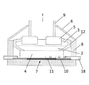
Figure 1 schematically shows a Hall-Heroult aluminium-production cell 1
comprising a carbon
cathode cell bottom 4, a pool 2 of liquid cathodic aluminium on the carbon
cathode cell bottom 4, a
fluoride- i.e. cryolite-based molten electrolyte 3, containing dissolved
alumina on top of the
aluminium pool 2, and a plurality of anodes 5 suspended in the electrolyte 3.
Also shown is the
cell cover 6, cathode current collector bars 7 according to the invention that
lead into the carbon
cell bottom 4 from outside the cell container 8 and anode suspension rods 9.
As can be seen, the
collector bar 7 is divided in zones. Zone 10 is insulated electrically and
zone 11 is composed of
layers as shown in Figure 2, Figure 3, Figure 5 or Figure 6. Molten
electrolyte 3 is contained in a
crust 12 of frozen electrolyte. Steel bars 18 connected in electrical series
to the ends of the
collector bars 7 protrude outside the cell 1 for connection to external
current supplies.
Zone 10 of the collector bar is for example electrically insulated by being
wrapped in a sheet of
alumina or by being encased in electrically insulating glue or cement.
CA 02964835 2017-04-18
WO 2016/079605 PCT/IB2015/054325
Figure 2 shows a U-shaped profile 14 made of any type of temperature-resistant
conductive or
insulating material for example steel and the high electrically conductive
material 15 such as
copper inside the U-shaped profile 14, forming together the collector bar. As
shown, the collector
bar is optionally surrounded by a coke bed (i.e. of ramming paste) 13 to
decrease the electrical
resistance towards the carbon cathode. The free top surface 16 of the high
conductive material
can be made rough to minimize the electrical contact resistance. In one
variation, the sides of the
U-shaped profile do not extend to the top of the highly electrically
conductive material and in
another variation the sides of the U-shaped profile are wider than and spaced
apart from the
highly electrically conductive material.
Figure 3 shows a U-shaped profile 14 made of any type of temperature-resistant
conductive or
insulating material for example steel and high conductive material 15 such as
copper, forming
together the collector bar in the case of using the "embedded" collector bar
inside the carbon
cathode 4 in this embodiment, contrary to Figure 2 where the top of the
copper/metal 15 is flush
with the open top of the U-shaped profile 14, here the copper/metal 15 is
separated from the two
lateral sides of the U-shaped profile thereby increasing the direct electrical
contact surface to the
carbon cathode 4 on three sides. The lower side of the copper/metal 15 rests
on the flat bottom of
the U-shaped profile 14 as mechanical support.
Figure 4 shows a typical impact of using the copper/metal bar on the current
density at the surface
of the cathode seen from the cathode center (point "0.0") to the edge of the
cathode (point "1.8").
These results will be discussed later.
Figure 5A shows the cathode 4 enclosing the high electrically conductive
material 15 and glue 16
around the highly conductive material, this glue being electrically
conductive.
Fig 5B shows the cathode 4 enclosing a bar 15 of high electrically conductive
material of
rectangular section in direct contact with the carbon cathode 4.
Figure 6 shows the cathode 4, the high electrically conductive material 15 and
glue 16 around the
highly conductive material, and refractory bricks 17. The highly conductive
material 15 is glued to
the carbon cathode 4 but only on the lower part of the cathode, the sides and
lower part of the
cathode being replaced by refractory bricks 17 such as Schamotte or any type
of electrically
insulating or even electrically conductive material such as ramming paste.
Figure 7 shows the cathode 4, the high electrically conductive material 15 and
the glue 16 around
the highly conductive material and on the contacting surfaces with a
transition joint formed by a
steel bar 18 leading current outside the cell. The end of the collector bar
can be press fitted in a
11
machined section in the steel bar 18, in a hole, or can be glued with the same
glue. Another type of
connection can be the use of a steel transition joint split in two
longitudinal parts that are clamped
over the collector bar by a bolted connection or weld.
Figure 8 shows the cathode 4 from the bottom, with two edge-to-edge bars of
high electrically
conductive material 15 separated by an expansion gap 15G and bolted to a steel
bar 18 leading the
current outside the cell. By using this bolted connection use is made of the
two highly conductive
metal elements 15 that can be spaced apart also inside the cathode to provide
a thermal expansion
gap inside the cathode.
Figure 9 shows an alternative connection where a steel bar 18 is made of two
separate elements
connected together by a bolted system 19. As shown, the end of the highly
electrically conductive
material 15 is also secured in the end of the split steel bars 18 by the same
bolted system 19.
Figure 10A shows the highly conductive material 15 of the current collector
bar machined to create
a central groove 27 extending over the main part of the height of the bar of
highly conductive
material, allowing for thermal expansion. In this example, the highly
conductive
material 15 is coated with electrically-conductive glue 16 which glues it to
the cathode 4.
Figure 10B shows the highly conductive material 15 of the current collector
bar machined to
create a central groove 27 extending over the main part of the height of the
bar of highly
conductive material, allowing for thermal expansion. In this example, the
highly conductive
material 15 is in direct contact to the carbon cathode 4. Instead of a
machined groove, two or
more bars of highly conductive material can be spaced from one another in
spaced facing
relationship.
Figure 10C shows the highly conductive material 15 of the current collector
bar machined to create
a central groove 27 extending over the main part of the height of the bar of
highly conductive material
allowing for thermal expansion. In this example the highly conductive material
15 is in direct contact to the carbon cathode and is supported from underneath
by a U-shaped
steel beam 14 wider than the highly electrically conductive material.
Figure 11 shows highly conductive material 15 whose upper surface is shaped by
a series of ribs or
other projections to increase the surface area between the cathode 4 and the
highly conductive
material 15 which is glued by a layer of electrically conductive glue 16 to
the cathode block 4.
Figure 12 shows the highly conductive material layer 15 of the current
collector bar, in direct
contact to the carbon cathode 4 by its upper side face and fitting over and
contacting a central
12
Date recue/date received 2021-10-19
CA 02964835 2017-04-18
WO 2016/079605 PCT/IB2015/054325
folded fin 14a of a U shaped steel beam 14 by its lower side face. There can
be more than one
vertical folded fin 14a as part of the U beam section 14.
Figure 13A shows highly conductive material 15 split into two separate
conductive parts by a
central vertical fin 14a of a wide U-shaped steel beam 14, each conductive
part being in direct
contact to the carbon cathode 4 from its upper sides and lateral faces.
Figure 13B shows the highly conductive material 15 split into two separate
conductive parts by a
central vertical fin 14a of a wide U-shaped steel beam 14, each conductive
part being electrically
insulated, over some segments of its length where insulation is required,
namely in zone 10
(Figure 1), from the carbon cathode 4 by a layer 20 of electrically insulating
material deposited
between the upper sides and the lateral faces of the conductive material and
the carbon cathode
4.
Figure 130 shows highly conductive material 15 split into two separate
conductive parts by each
of two separate vertical fins 14a of a U-shaped steel beam 14, each conductive
part being in direct
contact to the carbon cathode 4 from its upper sides and lateral faces. There
can be more than
two vertical fins 14a.
Fig 14 shows a bar of highly conductive material 15 in direct contact with the
carbon cathode 4 by
its upper and lateral sides. The lower side of the highly conductive material
15 is supported by a
"flat" steel beam 14b or by ramming paste or glue which is coextensive with
and supports the
highly conductive material 15. As described previously, the highly conductive
material can be split
by a groove or there can be more than one part of highly conductive material
spaced apart from
one another. The support beam 14b can be made of several layers, e.g. a steel
layer over
ramming paste.
Figure 15 shows a slotted copper tube 15A inserted in a cylindrical hole in a
graphite carbon block
4. The copper tube 15A is slotted along its length to provide a sufficient gap
to accomodate for
thermal expansion of the copper tube 15A as the cell reaches its operating
temperature. The outer
surface of the slotted tube 15A is preferably in direct electrical contact
with the graphite of block 4.
Figure 16 shows a solid copper rod 158 inserted in a hole in a graphite carbon
block 4. In this
case, expansion allowance can be achieved by precision fitting. In other
words, the diameter of
the cylindrical hole in the block 4 and the diameter of the rod 15B before
insertion are so
calculated that the rod fits comfortably in the hole and, as the temperature
of the cell rises, the rod
15B expands to fit tightly in the hole.
13
CA 02964835 2017-04-18
WO 2016/079605 PCT/IB2015/054325
Figure 17 shows two copper rods inserted in holes in a graphite carbon block
4, one rod 15B
being a plain cylindrical rod as in Figure 16 and the other rod 15B' having a
diametral gap for
thermal expansion.
Figures 15, 16 and 17 show copper bars of circular cross-section, but it is
noteworthy to mention
that the concept can be applied to any geometry of the hole and inserted
bar/tube. The illustrated
circular hole containing the copper conductor has the advantage of being
sealed from underneath
by the underlying carbon of the block. There is therefore no need for a
supporting U-shaped beam
for underneath support.
Figure 18 is a perspective view of a particular embodiment for connecting the
outer part of a highly
conductive (copper) bar to a transition joint. As shown, a copper bar 15 is
bent into U-shape with
two legs that are embedded in grooves in the underside of a graphite cathode
block 4 from which
the two legs protrude. The short section 15C at the protruding end of the U-
shaped copper bar 15
is press fitted in a transverse groove located towards the end of a steel
transition joint 18. An end
part of this transition joint 18 fits in between the two legs of the copper
bar 15 and the transition
joint 18 is deeper than the thickness of the legs of the copper bar 15.
Overall, the cross-sectional
area of the transition joint 18 is greater than the combined cross-sectional
area of the two legs of
the copper bar 15. A tight fit of the copper bar 15 with the transition joint
18 can be provided by
thermal expansion of the copper in the transverse groove of the transition
joint 18.
Further description of the high conductivity collector bars
The use of high conductivity collector bars can decrease the voltage drop from
the liquid metal 2
and the end part of the collector bars. The copper or other high conductive
material 15 with or
without a U-shaped profile 14 or support beam 14b also helps to decrease the
anode to cathode
distance (ACD) allowing a decrease of the specific energy consumption, and an
increase in the
height of the cathode leading to increased cell lifetime.
The lengths L-1, L2 and L3 (Figure 1) are optimized in function of the busbar
system and of the cell
geometry in order to optimize the cell stability. Indeed, the redistribution
of the current through the
collector bars allows for a much better magneto-hydrodynamic cell state that
will allow decreasing
the ACD while increasing the current and hence minimizing the energy
consumption. This is
reflected by a homogeneous vertical current density in a horizontal section in
the middle of the
liquid metal pool.
A typical example of current density is shown in Figure 4 for a standard cell
and for a cell
according to the invention in Figure 3 or Figure 5A. The vertical current
density (Jz) depends on
14
CA 02964835 2017-04-18
WO 2016/079605 PCT/IB2015/054325
the location in the liquid metal, ie. Jz=Jz(x,y,z) in a (x,y,z) coordinate
system. When moving from
the edge of the external part of the shadow of one anode (x= -X) to the edge
of the shadow of the
neighboring anode (x=XL) in an horizontal plane inside the liquid metal, the
absolute value of the
vertical component of the current density (lJz(x)I) varies typically as shown
in Figure 4. When
optimizing the collector bars by using a high conductivity metal 15, such as
copper in direct
electrical contact with the graphite cathode, contained in a U-shaped profile
14 or directly fitted
into a cathode slot, lJz(x)I is reduced by a minimum of 50% as shown in Figure
4 (right hand part).
The section of the collector bar is such that the heat extraction is minimum
from the side of the
carbon cathode to the end of the collector bar. In fact it is dimensioned in
such a way as to obtain
.. a temperature drop of around 200 C outside, and a voltage drop as low as
possible.