Note: Descriptions are shown in the official language in which they were submitted.
CA 02964850 2017-04-18
- 1
METHOD FOR COMPENSATING LOAD PEAKS DURING ENERGY
GENERATION AND/OR FOR GENERATING ELECTRICAL ENERGY AND/OR
FOR GENERATING HYDROGEN, AND A STORAGE POWER PLANT
The invention concerns a method of compensating for load peaks during the
generating of electrical energy and/or for the particularly decentralized
generating
of electrical energy, also in particular from regenerative energy sources such
as
biogas from biomass fermentation or synthesis gas from biomass gasification,
or
from fossil fuels such as natural gas, by utilizing the heat of heated carrier
gas for
the electricity generation, especially in a thermoelectric storage power
station,
io and/or for the utilization of the heat of heated carrier gas for
hydrogen generation,
especially in a gasification process. Furthermore, the invention concerns a
thermoelectric storage power station.
The development of renewable energy is leading to a change in the generation
structure in the electricity market. Supply-dependent electrical energy from
renewable energy sources such as wind power, biomass, and photovoltaics will
make up a majority of the electricity supply in the future. The available
technologies for electricity generation from regenerative energy sources,
however,
only permit a limited degree of precision in predictions of the volume of the
electricity to be generated, so that fluctuations occur on various time
scales,
namely, ranging from seasonal fluctuations during the course of the day to
short-
term fluctuations. These fluctuations amplify the fluctuations occurring in
electricity
demand and increase the need for ways of compensating for load peaks.
Compensation for load peaks at present is generally done through different
market structures in which operators of different generating and storage
technologies are participating. Furthermore, the energy system is faced with a
conversion from a centralized to a decentralized generation of electrical
energy
from fossil and regeneratively produced energy sources. This is producing new
requirements on the network infrastructure, since the problem of network
stabilization is being shifted increasingly from the transmission network
layer to
the layer of the distribution networks. However, so far these have little
infrastructure for the active control of the networks.
CA 02964850 2017-04-18
- 2 -
The problem which the present invention proposes to solve is to provide a
method
and a storage power station of the aforementioned kind which, with good
economy and high efficiency, compensate for generation peaks and valleys in
the
generating of electrical energy and can thereby make a contribution to load
management in the electricity network, wherein energy will be stored during
times
of high electricity generation and slight electricity demand and then released
during load peaks. In particular, it should be possible to reduce excess
capacity in
the electricity network and provide electric power during brief high
consumption
peaks in the shortest of time. Furthermore, the method and the storage power
io station should enable, in particular, decentralized electricity
generation and/or
hydrogen generation with good economy and high efficiency.
The aforementioned problems are solved by a method with the features of claim
1
and by a storage power station with the features of claim 13. Advantageous
embodiments will emerge from the subclaims.
The method according to the invention enables a utilization of the heat of
highly
heated carrier gas, especially hot air, for the electricity generation in a
power
station process or for hydrogen generation, especially in a gasification
process,
wherein first of all a carrier gas, such as air, is heated to a specified
target
charging temperature in at least one gas heater of a storage power station.
The
hot carrier gas serves for the thermal charging of at least one heat storage
module of a plurality of heat storage modules of the storage power station,
resulting in a release of heat from the hot carrier gas from the gas heater to
a heat
storage material of the heat storage module (charging cycle). In order to
generate
hot gas in sufficient amount and/or with sufficiently high target charging
temperature for the charging of the heat storage modules, a plurality of gas
heaters can be used. A maximum target charging temperature for the heating of
the carrier gases in the gas heater may amount to 1000 C to 1300 C, preferably
1100 C to 1200 C. Each heat storage module can be matched up with a separate
gas heater.
During the time-delayed thermal discharge of at least one heat storage module,
preferably a plurality of heat storage modules, the usable stored heat or the
CA 02964850 2017-04-18
- 3 -
usable caloric content of the heat storage modules is utilized for the heating
of
cold carrier gas, especially cold air, wherein cold carrier gas flows through
at least
one heat storage module and heat is transferred from the heat storage material
to
the carrier gas (discharge cycle). The carrier gas upon flowing through the
heat
storage module is heated to a specified discharge temperature and exits at
this
temperature level from the heat storage module. The specified discharge
temperature required for a utilization of the heat can amount to at least 500
C,
preferably at least 600 C, up to 900 C, more preferably up to 800 C. The heat
of
the hot carrier gas generated during a discharge cycle is then utilized in a
power
io station or gasification process. Both the charging cycle and the
discharge cycle
can be associated with a partial or complete charging and discharge of a heat
storage module. The usable caloric content of a heat storage module results
from
the specific heat capacity of the heat storage material, the mass of the heat
storage material or the size of the heat storage module and the (mean) heat
storage temperature achieved during a charging or discharging cycle or
process.
For a utilization of the heat of the carrier gas for generating electricity in
a power
station process, it can be provided that heat from carrier gas heated in at
least
one heat storage module is transferred to a working fluid of the power station
process, especially a working fluid of a steam power process. Preferably, the
working fluid will be water. In particular, a utilization of the heat
transferred to the
carrier gas in a conventional steam power plant can be provided, wherein the
power rating of the power plant is more than 5 MW, preferably more than 10 MW,
more preferably more than 50 MW, especially preferably more than 100 MW.
However, the power rating can also amount to several 100 MW. In a steam power
process the heat of the carrier gas can be utilized for steam production, for
preheating of the feed water, and/or for superheating of steam. Basically,
however, it is also possible to supply the heat transferred to the carrier gas
in the
form of hot air to the combustion chamber of a (conventional) coal-fired power
plant and/or a combined-cycle power plant, in order to burn a fuel such as
coal or
gas. The power rating of the coal-fired power plant and/or the combined-cycle
power plant in this case can preferably correspond to the above mentioned
power
rating of a steam power plant. Alternatively, the invention also enables a
utilization
CA 02964850 2017-04-18
- 4 -
of the heat transferred to the carrier gas in a gasification process in order
to
generate hydrogen. For example, steam can be generated with the heat, which
can then be used in an allothermal coal gasification process.
The thermoelectric storage power station according to the invention can
comprise
at least one compressor for compressing the carrier gas, at least one gas
heater
for heating the carrier gas, a plurality of heat storage modules for storing
the heat
of heated carrier gas and at least one heat exchanger, such as a steam
generator, for transferring the heat from heated carrier gas to a working
fluid of a
steam power process. Of course, the storage power station according to the
io invention can furthermore comprise additional components of a steam
power plant
known from the prior art, such as a feed water pump, a condenser and a steam
turbine.
If the heating of the carrier gas is done in the gas heater by transformation
of
electrical energy into thermal energy, for which purpose the gas heater can
comprise at least one electrical heating resistor, the method according to the
invention and the storage power station according to the invention make a
contribution to the load management in the electricity grid, storing
electrical
energy in the form of heat during a charging cycle at times of high
electricity
production and low electricity demand. During load peaks, at least one heat
storage module is then discharged in a discharge cycle and the hot carrier gas
so
produced is used for electricity production, for example, to turn water into
steam
for a steam power process. The electrical energy produced can again be
released
to the electricity grid. An operator of the storage power station according to
the
invention can offer system services and take part in the regulated energy
market.
Thanks to the heat storage modules used, a simple and economical storage of
electrical energy in the form of heat is possible, wherein electric power can
be
made available in a flexible and very brief as well as economical manner
during
transient high consumption peaks.
Especially preferably, a purely electrical heating of the carrier gas in at
least one
electrical air heater is provided by the transformation of electric energy
into
thermal energy. It is then not necessary to burn a fuel in order to produce
hot
CA 02964850 2017-04-18
- 5 -
carrier gas, so that an additional releasing of carbon dioxide is avoided.
The production of a hot carrier gas can also alternatively or additionally be
done
by the burning of at least one fuel in at least one combustion chamber of the
gas
heater, for example by the burning of biogas from biomass fermentation and/or
synthesis gas from biomass gasification. The use of natural gas is also
possible
and advantageous. Of course, an energy production is also possible with the
use
of other fossil fuels, such as synthesis gas from coal gasification. Solid
fuels can
also be used. Thus, the power station according to the invention can help
cover
the base load, for example, in the vicinity of a biogas plant, which enables
an
io economical electricity production. In particular, the power station
according to the
invention is distinguished for being an isolated operation, when electricity
is
produced in a decentralized manner from preferably regeneratively produced
fuels.
It may be expedient for the hot gas production in the air heater to be equally
possible by transforming electrical energy into thermal energy and by burning
at
least one fuel. In this way, needs-based support of the grid infrastructure is
possible by compensating for load peaks and generating electricity to cover
the
base load.
It is not ruled out that waste heat or process heat from a secondary process
also
be utilized in the gas heater for the production of hot gas.
In one expedient embodiment of the method according to the invention, a
plurality
of heat storage modules connected in series can form a heat storage series,
wherein a carrier gas is heated in at least one gas heater to a specified
target
charging temperature and then flows in succession through several heat storage
modules of the heat storage series, especially all the heat storage modules.
The
heat storage modules are in this way heated or "charged" to the same or
different
heat storage temperatures depending on the size of the hot gas volume flow,
the
level of the target charge temperature of the hot carrier gas at the exit from
the
gas heater, the size of the particular heat storage module and/or the thermal
capacity of the heat storage material used. Preferably, all heat storage
modules
CA 02964850 2017-04-18
- 6 -
are outfitted the same and have equal-sized usable caloric contents in the
fully
charged state.
In an especially preferred embodiment, there is provided an at least pairwise
actuation of several heat storage modules. The at least pairwise actuation of
heat
storage modules simplifies the design of the heat storage modules in terms of
required pipeline lengths and their interconnection and thus enables an
economical fabrication of the modules. By a "pairwise actuation" in the sense
of
the invention is meant the joint actuating of at least two heat storage
modules,
preferably precisely two heat storage modules, for charging, i.e., for the
joint
io charging in series connection to allow for the flow of hot carrier gas
through them.
At least two heat storage modules can form a heat storage pair. Several heat
storage pairs of a heat storage system can be actuated independently of one
another or separately. This can be achieved by a suitable pipeline layout and
valve control in the heat storage system. During the charging of a heat
storage
pair, the heat storage modules of the particular heat storage pair can then be
arranged in series and the carrier gas can flow through them in succession.
Accordingly, a pairwise actuation can be provided for the discharge of the
heat
storage modules.
Basically, a separate actuating of heat storage modules during the charging
and/or discharging is also possible, in which case each individual heat
storage
module is actuated as needed, i.e., it can be opened up for a flow of carrier
gas
through it.
Hot carrier gas from a gas heater with a high, preferably with a maximum
target
charge temperature can enter into at least the first heat storage module of a
heat
storage series, in which case the hot carrier gas cools down during the
charging
of the first heat storage module and exits with a lower exit temperature from
the
heat storage module. The carrier gas is then taken to the next heat storage
module of the heat storage series for charging. With increasing degree of
charging of a heat storage module or with increasing heat uptake of the
storage
material, the exit temperature of the carrier gas flowing from the particular
heat
storage module also increases during a charging cycle. The exit temperature of
CA 02964850 2017-04-18
- 7 -
the carrier gas upon exiting from a preceding heat storage module corresponds
preferably substantially to the entrance temperature of the carrier gas upon
entering the next heat storage module. Preferably the heat storage modules of
a
heat storage series are heated to different degree during a charging cycle,
where
the heat content of the heat storage modules attained during a charging cycle
and
usable during the discharge and preferably the heat storage temperature
decrease in stages in the flow direction of the carrier gas from one heat
storage
module to another. Accordingly, the exit temperature of the carrier gas
decreases
from one heat storage module to another.
io Again preferably, during each charging cycle at least a last heat
storage module
of the heat storage series is not fully charged. The carrier gas can then exit
cold at
the end of a charging cycle from this heat storage module, that is, with an
exit
temperature of, for example, less than 100 C, preferably less than 50 C,
especially less than 30 C. Thanks to the described procedure, during the
charging, a simple and economical storage of electrical energy is possible,
wherein the heat contained in the carrier gas can be stored almost completely
in
the heat storage modules and again be made available in the near term.
The carrier gas exiting from a heat storage module during its charging can be
utilized for the charging of a following heat storage module of the heat
storage
series, until the exit temperature of the carrier gas from the preceding heat
storage module drops below a specified minimum exit temperature. The minimum
exit temperature can be less than 200 C, preferably less than 100 C, more
preferably less than 50 C, especially preferably less than 30 C. If the
minimum
exit temperature is still high enough, the carrier gas exiting from a heat
storage
module can be utilized for the purpose of maintaining warmth, for example, in
the
steam power process.
During the charging of several heat storage modules connected in series, the
charging of a following heat storage module of the series can also be done at
least partly by direct supply of hot carrier gas from a gas heater, especially
if the
exit temperature of the carrier gas from a preceding heat storage module of
the
series drops below a specified minimum exit temperature. The directly supplied
CA 02964850 2017-04-18
- 8 -
hot carrier gas from the gas heater may then have the target charge
temperature
which is reached in the gas heater, so that a preferably complete charging of
a
following heat storage module is possible. If the exit temperature of the
carrier gas
from a preceding heat storage module does not drop below a specified minimum
temperature, yet is not high enough to enable a complete charging of the
following
heat storage module, the charging of the following heat storage module can be
done by the carrier gas from a preceding heat storage module of the heat
storage
series and by supplying hot carrier gas from the gas heater. Thus, thanks to
the
direct supply of hot carrier gas, a definite high charging state of the
following heat
io storage module can be achieved in simple manner.
Basically, it is also possible to charge several heat storage modules in
parallel,
each heat storage module being supplied with a separate hot carrier gas
stream.
Preferably, here as well, at least a pairwise actuation of several heat
storage
modules can be provided. For example, at least every two heat storage modules
can form a heat storage unit or a heat storage pair. Several heat storage
units can
be charged in parallel, but the individual heat storage modules of a heat
storage
unit are hooked up in series and carrier gas flows through them in succession.
The heat storage units can preferably be actuated independently of each other.
A
corresponding control system can be provided for the discharge.
Several gas heaters can be provided in order to generate separate carrier gas
streams, each heat storage module being assigned to at least one gas heater.
From each gas heater a carrier gas stream emerges with a specified target
charging temperature for the charging of the associated heat storage module.
The
target charge temperatures of the carrier gas streams can be the same or
different. Preferably, a maximum target charge temperature is achieved in all
gas
heaters between 1000 C and 1300 C. The parallel charging of several heat
storage modules makes possible in particular a simultaneous high, preferably
complete, charging of the heat storage modules in very short time.
In order to create a heated carrier gas stream for providing heat in the power
plant
and/or gasification process, several heat storage modules can be discharged in
parallel, each heat storage module being assigned a separate cold carrier gas
CA 02964850 2017-04-18
- 9
stream. In order to provide hot gas of a specified target discharge
temperature for
utilization of heat in the power plant and/or gasification process, it is
advisable to
discharge at least one heat storage module with a lower heat storage
temperature
and at least one heat storage module with a higher heat storage temperature in
parallel and to merge the heated carrier gas so produced from both heat
storage
modules in order to adjust a specified target discharge temperature.
Preferably it
is provided that a heat storage module with the relatively lowest heat storage
temperature and at least one heat storage module with a relatively next higher
heat storage temperature from a plurality of heat storage modules are
discharged
io in
parallel in order to provide a carrier gas stream with a desired target
discharge
temperature. The discharge of the heat storage modules is preferably done at
the
same time. As a result, at least two different hot carrier gas streams are
mixed in
order to adjust or regulate a specified target discharge temperature of the
carrier
gas required for the subsequent heat transfer to the power plant and/or
gasification process. This target discharge temperature can be kept constant
by a
suitable volume regulation of the merged carrier gas streams over the entire
discharge cycle of the heat storage modules. The mixing of different warm
carrier
gas streams enables a simple regulation of the target discharge temperature
and
a complete discharge of heat storage modules whose heat content is too low to
heat a particular carrier gas stream to the target discharge temperature. A
charged heat storage module with a lower heat content and/or with a lower heat
storage temperature can thus be used during a discharge cycle as a bypass for
a
charged heat storage module with a higher heat content and/or a higher heat
storage temperature.
Alternatively and/or in addition, a merging of heated carrier gas during the
discharge of at least one heat storage module with cold carrier gas,
especially
cold air, can be provided in order to accomplish a cooldown of the heated
carrier
gas to a specified target discharge temperature of the carrier gas. This
allows a
simple and precise regulating of the target discharge temperature of the
carrier
gas.
In order to ensure a certain (high) target discharge temperature for the heat
CA 02964850 2017-04-18
- 10 -
utilization in a process for the production of electricity and/or hydrogen, it
can also
be provided that carrier gas heated in at least one heat storage module is
mixed
directly with hot carrier gas from the gas heater. The carrier gas from the
gas
heater is preferably at the maximum target charge temperature.
Furthermore, the heat transferred to the carrier gas in a gas heater can also
be
utilized directly, without interim storage of the heat in a heat storage
module, in a
process for the production of electricity and/or hydrogen. For example, it is
possible for a portion of the hot carrier gas heated in the gas heater to
bypass the
heat storage modules and be supplied to at least one steam generator of the
io steam power process in order to keep the steam generator warm during a
charging cycle of the heat storage module.
In one preferred embodiment of the method according to the invention, during a
discharge cycle at least one heat storage module is fully discharged and at
least
one heat storage module is only partly discharged. During a complete
discharge,
the exit temperature of the carrier gas from the heat storage module at the
end of
the discharge cycle is preferably less than 200 C, preferably less than 100 C,
more preferably less than 50 C, especially preferably less than 30 C. In
particular,
it is provided in this context to fully discharge at least one heat storage
module
whose usable heat content and/or whose heat storage temperature is too low to
heat the carrier gas by itself to a specified target discharge temperature,
which
depends of course on the size of the carrier gas volume flow. On the other
hand,
heat storage modules with higher heat content, especially a higher heat
storage
temperature, are not fully discharged during a discharge cycle. This applies
especially to the first heat storage module or several heat storage modules of
a
heat storage series through which hot carrier gas flows at first during a
charging
cycle and which are heated to a storage temperature above the target charge
temperature. Advisedly, during a discharge cycle, at first the heat storage
module
with the lowest heat content, especially the lowest heat storage temperature,
is
discharged and then heat storage modules each with increasing usable heat
content and/or each with rising heat storage temperature.
During very high demand for electrical energy, it is of course also possible
to fully
CA 02964850 2017-04-18
- 11 -
discharge all heat storage modules. Depending on the heat content of a heat
storage module and/or the heat storage temperature, a temperature regulation
may also be required by supplying of cold carrier gas in order to maintain a
specified target discharge temperature. In this way, the required target
discharge
temperature can be reliably maintained.
The hot carrier gas generated during a discharge cycle can also be used
according to the invention for steam generation in a steam power process,
wherein the electrical efficiency of the storage power station can be boosted
in
that the heated carrier gas at first is expanded in an expander or a gas
expansion
io turbine of the storage power station and then supplied to a steam
generator. The
absolute pressure of the carrier gas before entering the gas expansion turbine
may be up to 20 bar. For this purpose, a corresponding compression of the cold
carrier gas is provided. If the electricity generation is done only in the
steam
power process, an absolute pressure of the carrier gas between 2 and 5 bar,
preferably between 3 and 4 bar, is enough to supply the heated carrier gas to
a
steam generator. Here as well, an upstream expander or a gas expansion turbine
can be provided in order to boost the electrical efficiency of the storage
power
station. The expander can be provided downstream from the heat storage
modules in the flow direction of the carrier gas and upstream from a steam
generator.
In the utilization of the heat storage power station to cover the base load,
the
carrier gas can be heated in at least one gas heater and then be used directly
in
the steam process for generation of steam, that is, without charging and
discharging the heat storage modules. In particular, it may be provided here
that
carrier gas is heated in the gas heater by the burning of a fossil fuel, such
as
natural gas. Alternatively, of course, it is also possible to use non-fossil
fuels, such
as biogas. Moreover, in particular, an indirect heating of the carrier gas can
be
provided, so as not to contaminate the carrier gas with combustion gases.
In order to reduce environmentally harmful emissions, a circulation of the
carrier
gas can be provided. The carrier gas in this case is not vented to the
surroundings
after the heat transfer to the working fluid, but instead utilized for another
charging
CA 02964850 2017-04-18
- 12 -
_
of the heat storage modules. There may be a substantially closed carrier gas
system. If the carrier gas is vented to the surroundings after a heat transfer
to the
working fluid, on the other hand, there is an open carrier gas system, which
requires a supply of fresh carrier gas for a subsequent charging cycle.
Further features, benefits and application possibilities of the present
invention will
emerge from the following description of sample embodiments with the help of
the
drawing and from the drawing itself. All features described and/or graphically
portrayed, either alone or in any given combination thereof, form the subject
matter of the present invention, regardless of their summarization in the
claims or
io through referrence back to the claims.
In the drawing are shown:
Fig. 1
a schematic process flow chart of a method according to the
invention for compensating for load peaks in the generating of
electrical energy and/or in particular for the decentralized generating
of electrical energy in a storage power station according to the
invention with a plurality of heat storage modules during the charging
of the heat storage modules, wherein an open carrier gas system is
provided,
Fig. 2
a schematic process flow chart of the method according to the
invention per Fig. 1 during the discharge of the heat storage
modules,
Fig. 3
a schematic process flow chart of an alternative embodiment of the
method according to the invention during the charging of the heat
storage modules, wherein a closed carrier gas system is provided,
Fig. 4 a schematic
process flow chart of the method according to the
invention per Fig. 3 during the discharge of the heat storage
modules, and
Figs. 5 to 8 schematic representations of the possible interconnecting of four
CA 02964850 2017-04-18
- 13 -
heat storage modules during charging and discharging.
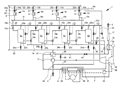
Figures 1 to 4 show a thermoelectric storage power station 1 for utilization
of the
heat of heated carrier gas 2 for electricity generation, with a compressor 3
for
compressing the carrier gas 2, with a plurality of gas heaters 4a-d for
heating the
carrier gas 2, with a plurality of heat storage modules 5a-d for storing the
heat of
heated carrier gas 2 and with a steam generator 6 for the transfer of the heat
from
heated carrier gas 2 to a working fluid 7 of a steam power process. The
carrier
gas 2 is preferably air or some other suitable gas. The working fluid 7 is
preferably
water.
io Each gas heater 4a-d in the present case comprises a combustion chamber
8 for
the use of a gaseous fuel 8a in particular, such as biogas or natural gas, and
an
electric heater 9, having heating conductors, such as ones made of silicon
carbide
or a suitable metal, and which can be connected to a power source. When the
power source is switched on, the heating conductors heat up and give off their
heat to the carrier gas 2. The carrier gas 2 with suitable design of the gas
heater
4a-d can be heated to a target charge temperature of, for example, 1200 C at
maximum. The target charge temperature is dictated by a control and/or
regulating mechanism, not shown.
In order to compensate for load peaks in the generation of electric energy,
the
carrier gas 2 is at first heated in at least one gas heater 4 to the target
charge
temperature. The volume regulation of the system is designed so that,
depending
on the supply of electric energy, the specified target charge temperature for
the
carrier gas 2 is maintained at the exit from a gas heater 4a-d. It is also
possible to
operate several gas heaters 4a-d at the same time for the heating of the
carrier
gas 2, each time supplying a partial stream of the carrier gas 2 to a gas
heater 4a-
d by a gas line 10a-d and heating it there. The partial streams after the
heating
can also be brought together by a collecting line 11 and be supplied to a
first heat
storage module 5a in order to charge the heat storage module 5a with heat by
releasing heat from the heated carrier gas 2 to a heat storage material of the
heat
storage module 5a. For the charging of the first heat storage module 5a, a
supply
valve 12a is opened, while other supply valves 12 b-d which connect the other
CA 02964850 2017-04-18
- 14 -
heat storage modules 5b-d to the associated gas heaters 4b-d are closed.
In the embodiment shown, the heat storage modules 5a-d are hooked up in series
and form a heat storage series, wherein the carrier gas 2 heated to the target
charge temperature in the gas heater 4a during a charging cycle then flows
through the heat storage modules 5b-d of the heat storage series and the heat
storage modules 5a-d are heated. The carrier gas 2 at the beginning of the
charging cycle leaves the heat storage module 5a across a three-way valve 13a,
being at first cold. With increasing heat uptake from the storage material,
the
temperature of the carrier gas 2 flowing out from the heat storage module 5a
increases.
The three-way valve 13a has two switching possibilities. The carrier gas 2 can
either be taken via the collecting line 14, the outlet valve 15 and a heat
exchanger
16 to a chimney 17 as vented air. But for a charging of the following heat
storage
modules 5b-d, the carrier gas 2 if its heat content or heat storage
temperature is
sufficient is taken across the three-way valves 13a-c to the following heat
storage
modules 5b-d. This occurs via the supply lines 18a-c. In this way, the thermal
energy contained in the carrier gas 2 can be stored almost completely in the
heat
storage modules 5a-d.
The heat storage module 5b is preferably designed such that cold carrier gas 2
still emerges from the heat storage module 5b even when the heat storage
module 5a is fully charged. A full charging occurs when the exit temperature
of the
carrier gas 2 from the heat storage module 5a corresponds to the entrance or
target charge temperature of, for example, 1200 C. The carrier gas 2 leaving
the
heat storage module 5a is taken across the three-way valve 13b and the supply
line 18b to the third heat storage module Sc. Alternatively, the carrier gas 2
can be
vented to the surroundings via the collecting line 14. The possibility exists
of
likewise charging the heat storage module 5d or switching in other heat
storage
modules, not shown.
The gas heaters 4a-d can supply the individual heat storage modules 5a-d with
heated carrier gas 2, which is possible via the charging lines 19a-d and
possibly
CA 02964850 2017-04-18
- 15 -
other valves, not shown. In this way, a heat storage module 5b-d can be fully
charged even when the heat content of the carrier gas 2 coming from the
preceding heat storage module 5a-c is not enough for a full charging of the
following heat storage modules 5b-d. Preferably, however, it is provided that
the
hot carrier gas streams generated in the gas heaters 4a-d are merged by the
collecting line 11 and flow through the heat storage modules 5a-d in
succession,
starting from the first heat storage module 5a, for a charging of hot gas.
It is not depicted that, during a charging cycle of the heat storage modules
5a-d, a
partial stream of the hot carrier gas 2 from the collecting line 11 can be
mixed with
io a partial stream of cold carrier gas 2, supplied via the compressor 3,
and supplied
to the steam generator 6 to keep it warm. The temperature regulation can be
done
in terms of the size of the volume flows.
The heat storage modules 5a-d can be thermally insulated vessels in which a
heat
storing material, such as a ceramic bead fill, is disposed. Suitable heat
storage
materials are known to a skilled person. The heat storage material is heated
up by
the hot carrier gas 2 as the carrier gas 2 cools down. With a suitable design
of the
heat storage modules 5a-d, the efficiency of the transformation of electric
power
into heat and the transfer of the heat to the storage material can be more
than
90%, preferably more than n 95%.
During the charging of the heat storage modules 5a-d, the supplying of carrier
gas
2 occurs via an opened supply valve 20 to the compressor 3, with which carrier
gas 2 can be supplied across a preheater 21 and a collecting line 22 as well
as
other supply valves 23a-d to the gas heaters 4a-d. According to Fig. 1, the
entire
carrier gas 2 is taken only to the first gas heater 4a when the supply valve
23a is
open. The supply valves 23b-d are closed. But basically, as described above, a
heating of the carrier gas 2 can also be provided in several or all gas
heaters 4a-
d.
Fig. 2 shows schematically the discharge of the heat storage modules 5a-d of
the
storage power station 1 shown in Fig. 1. For the discharge mode, the supply
valves 23a-d are closed. Instead, other supply valves 24a-d are opened, so
that
CA 02964850 2017-04-18
- 16 -
cold carrier gas 2 for a parallel discharge of the heat storage modules 5a-d
is
forced across the compressor 3 and the collecting line 22 into the heat
storage
modules 5a-d. In this process, the carrier gas 2 is heated in the heat storage
modules 5a-d. Optionally, the carrier gas 2 can be taken in parallel across
all heat
storage modules 5a-d or it is possible to discharge only one or more heat
storage
modules 5a-d. The carrier gas 2 after exiting from the heat storage modules 5a-
d
can be brought together in a further collecting line 25. For this, the
collecting line
25 is connected by exit lines 26a-d to the heat storage modules 5a-d. From the
heat storage modules 5a-d, the carrier gas 2 exits at most with the target
charge
io temperature of 1200 C.
Furthermore, preheated carrier gas 2 can go by bypass lines 27a-d at least
partly
past the heat storage modules 5a-d and be fed to the collecting line 25. In
this
way, it is possible to mix hot carrier gas from the heat storage modules 5a-d
and
cold carrier gas 2 by an appropriate volume regulating system so that the
desired
target discharge temperature of the hot carrier gas 2 is adjusted. This target
discharge temperature can be, for example, between 600 C and 800 C. This
temperature is preferably kept constant over the entire discharging operation.
If
the exit temperature of the carrier gas 2 coming from a heat storage module 5a-
d
is higher than the desired target discharge temperature, a temperature
regulation
can be done via the respective bypass lines 27a-d.
When the heat storage modules 5a-d are arranged in a heat storage series, it
can
be provided to empty the heat storage modules 5a-d in dependence on the usable
heat content and/or the heat storage temperature of the particular heat
storage
modules 5a-d, wherein starting with a heat storage module 5d which may have
the lowest heat content and/or the lowest heat storage temperature the heat
storage modules 5c, 5b, 5a are discharged in succession, that is, in the
reverse of
the direction of charging. Thus, the discharge begins preferably with the heat
storage module having the lowest usable heat content and/or the lowest heat
storage temperature. After this, the respective heat storage module which has
the
lowest usable heat content or the lowest heat storage temperature in
comparison
to the remaining heat storage modules is discharged. However, not all heat
CA 02964850 2017-04-18
- 17 -
_
storage modules 5a-d need to be fully discharged. Thanks to the described
method, a high system efficiency can be achieved and the generated electric
power can be adapted according to the actual needs.
For example, if the exit temperature of the carrier gas 2 from the last heat
storage
module 5d of the heat storage series falls below a specified target discharge
temperature, a partial stream of the carrier gas 2 is transferred across the
preceding heat storage 5c in the heat storage series with a higher heat
content
and/or a higher heat storage temperature. The carrier gas streams are merged
together, so that the target discharge temperature is established. The heat
io storage module 5d then serves as a bypass, which is operated for as long
as it
takes to fully empty the heat storage module 5d. The desired target discharge
temperature of the carrier gas 2 is achieved in this case by discharging at
least
one upstream heat storage module 5a to 5c of the heat storage series, once
again
possibly having the temperature regulated by supplying cold carrier gas 2
across
at least one bypass line 27a-d.
The compressor 3 compresses the carrier gas 2 preferably to a system pressure
of up to 20 bar. The hot carrier gas 2 produced during a discharge cycle is
taken
across the collecting line 25 to an expander 28 and expanded in the expander
28.
In this process, the carrier gas 2 cools down, depending on its pressure
level. If
the use of an expander is not provided, the system pressure can be
significantly
lower and, for example, may be only between 3 and 4 bar (absolute). The
carrier
gas 2 exiting from the expander 28 serves for the generating and superheating
of
high-pressure steam in the steam generator 6. The steam generator 6 may have a
preheater 29, a steam drum 30 and a superheater 31. Otherwise, the steam
generator 6 corresponds to a typical design. The steam generated is taken to a
steam turbine 32. The expander 28 and the steam turbine 32 are connected to a
generator, not shown. Moreover, a deaerator 33 and a condenser 34 can be
provided.
The electrical efficiency of the storage power station 1 can reach 60%.
Furthermore, it is possible to divert heat for district heating. The thermal
efficiency
of remote heat utilization can reach 98%. Moreover, process steam can be
CA 02964850 2017-04-18
- 18 -
diverted out from the storage power station 1.
While Figures 1 and 2 show an operation of the storage power station 1 with an
open carrier gas system, the carrier gas 2 being vented as waste air into the
surroundings through the chimney 17, the possibility exists for taking the
carrier
gas 2 in a circuit. This is shown schematically in Figures 3' and 4, where
Fig. 3
shows the state during a charging cycle and Fig. 4 the state during a
discharge
cycle.
In the closed carrier gas system, preferably no supply of fuel gas and no
burning
of fuel gas in the combustion chambers 8 of the gas heaters 4a-d is provided,
but
it is possible in the case of indirect heat transfer. Instead, the heating of
the carrier
gas 2 is done preferably and exclusively by means of thermal conductors by
transforming electric energy into thermal energy. If the carrier gas 2 is
taken in a
circuit, the outlet valve 15 is closed during the charging of the heat
exchange
modules 5a-d. Instead, the circulation valves 35, 36 are opened, so that
carrier
gas emerging from a heat storage module 5a to 5d is taken across the
collecting
line 14 and a circulation line 37 to the compressor 3. The supply valve 20 is
closed, so that no supply of fresh carrier gas 2 to the carrier gas system
occurs. In
a discharge cycle, the carrier gas 2 after passing through the preheater 21 is
taken across a return line 38, an opened return valve 39 and the circulation
line
37 to the compressor and is then available for another charging of the heat
storage modules 5a-d. The circulation valves 35, 36 and another outlet valve
40,
which allows the carrier gas 2 during the discharge to be discharged in the
open
carrier gas system across an outlet line 41 and the chimney 17 (Fig. 2), are
closed.
As moreover appears from Figures 1 and 2, a further combustion chamber 42 can
be provided as part of a further gas heater, with which it is possible to heat
the
carrier gas 2 before entering the expander 28 by the burning of fuel gas 8a to
a
certain target temperature of, for example, 600 C to 800 C. The gas heater
can
be designed for direct or indirect heat transfer. This allows for the
utilization of the
storage power station 1 to cover the base load, for which a charging and
discharging of the heat storage modules 5a-d is not required. Furthermore, the
CA 02964850 2017-04-18
- 19 -
combustion chamber 42 can serve to provide hot gas during the charging of the
heat storage modules 5a-d for keeping machinery warm. The heating of the
carrier gas in the combustion chamber 42 can furthermore help lower the
electricity production costs.
Figs. 5 to 8 show schematically a connection example for the charging and
discharging of four heat storage modules 5a-d. Fig. 5 and Fig. 6 show the
connection during charging of the heat storage modules 5a-d, while Fig. 7 and
Fig. 8 show the connection during discharge of the heat storage modules 5a-d.
For the charging of the heat storage modules 5a-d, carrier gas 2 is heated in
a
io gas heater 4a, which is designed as an air heater, and then taken per
Fig. 5 to the
heat storage modules 5a-d. The carrier gas 2 can be air. The hot carrier gas 2
from the gas heater 4a flows successively through the series-connected heat
storage modules 5a-d. The heat storage modules 5a-d can be actuated in pairs
for carrier gas 2 to flow through them. This holds equally for charging and
discharging. In the embodiment shown, the first two heat storage modules 5a
and
5b shown at the left in Fig. 5 to 8 and the other heat storage modules 5c and
5d
shown at the right are each matched up with one heat storage pair or one heat
storage unit, the heat storage pairs being actuated and receiving the flow of
carrier gas 2 separately and independently of each other, due to the piping.
Of
course, it is also possible to match up more than two heat storage modules 5a-
d
with a separately actuated heat storage pair, if the storage layout comprises
more
than four heat storage modules 5a-d.
According to Fig. 5 and 6, two heat storage pairs are each hooked up in series
with two heat storage modules 5a, 5b and 5c, 5d and successively receive the
flow of hot carrier gas 2 from the gas heater 4a. The carrier gas 2 here is
taken in
a circuit per Fig. 5 through a circulation line 50 and, after exiting from the
fourth
heat storage module 5d shown at the right in Fig. 5, it returns across a
compressor 3 to the gas heater 4a. The gas control is achieved by a suitable
control system for a plurality of valves.
According to Fig. 6, a charging of the four heat storage modules 5a-d can also
CA 02964850 2017-04-18
- 20 -
occur such that hot carrier gas 2 from the gas heater 4a flows through the two
heat storage pairs with the heat storage modules 5a, 5b on the one hand and
5c,
5d on the other hand, in parallel. The carrier gas 2 exits with a specified
target
charge temperature from the gas heater 4a and is supplied with this
temperature
to the respective first heat storage module 5a or 5c of the respective heat
storage
pair. In this way, a complete charging is possible.
According to Fig. 6, the hot carrier gas 2 from the gas heater 4a is taken by
a
bypass line 43 past the two heat storage modules 5a, 5b of the first heat
storage
pair and thereby arrives at the heat storage module 5c of the heat storage
pair
io shown at the right in Fig. 6. Furthermore, it is possible to supply hot
carrier gas 2
from the gas heater 4a directly across a consumer line 44 to a consumer 45.
The
term "Consumer" in the sense of the invention encompasses any possible usage
of the heat of the carrier gas 2 in a power plant process and/or gasification
process.
Moreover, the connection per Fig. 6 allows fresh air 46 to be supplied via a
further
compressor 47 and a regulating line 52 to a mixing chamber 48, in order to
appropriately regulate the temperature of the hot carrier gas 2 before being
routed
on to the consumer 45. The fresh air 46 in this case lies at a significantly
lower
temperature than the hot carrier gas 2 emerging from the gas heater 4a.
During the discharge of the heat storage modules 5a-d, it can be provided per
Fig.
7 to supply fresh air 46, which forms the carrier gas 2, across the compressor
3,
47 and another bypass line 49 past the two heat storage modules 5c, 5d of the
right-hand heat storage pair shown in Fig. 7 and to the right-hand heat
storage
module 5b of the left-hand heat storage pair shown in Fig. 7 at right. The
fresh air
46 and the carrier gas 2 then flow through the two heat storage modules 5a, 5b
of
the heat storage pair shown in Fig. 7 at left and arrive across the bypass
line 43
and the consumer line 44 at the consumer 45. Here as well, if needed a supply
of
fresh air 46 to the carrier gas 2 can be provided via the regulating line 52
and the
mixing chamber 48 in order to adjust or regulate a particular utilization
temperature of the carrier gas 2 for the power plant process and/or
gasification
process.
CA 02964850 2017-04-18
- 21 -
Moreover, per Fig. 7, if the target discharge temperature of the carrier gas 2
is too
low upon exiting from the heat storage module 5a shown at far left in Fig. 7,
it is
possible to mix hot carrier gas 2 from the gas heater 4a with heated carrier
gas 2
from the heat storage module 5a in order to achieve a utilization temperature
of
the carrier gas 2 as required by the consumer 46.
According to Fig. 8, fresh air 46 can be supplied across the compressor 47, 3
and
a discharge line 51 to the last heat storage module 5d of the heat storage
pair
shown at right in Fig. 8. The carrier gas 2 heated in the heat storage modules
5c,
5d arrives by the bypass line 43 at the mixing chamber 48. Furthermore, fresh
air
1() 46 is supplied via the bypass line 49 to the heat storage modules 5a,
5b of the
other heat storage pair and heated there. The carrier gas 2 heated in the heat
storage modules 5a, 5b likewise arrives through the bypass line 43 at the
mixing
chamber 48. The two heat storage pairs are thus discharged in parallel, while
the
heat storage modules 5a, 5b and 5c, 5d of each heat storage pair in the series
are
discharged. Here as well, if need be, the temperature of the heated carrier
gas 2
can be regulated by supplying fresh air 46 via the regulating line 52 to the
mixing
chamber 48. The carrier gas 2 then goes to the consumer 45. Basically, a
direct
supply of hot carrier gas 2 from the gas heater 4a to the mixing chamber 48 is
also possible as needed, in order to increase the temperature of the carrier
gas 2
heated in the heat storage modules 5a-d.
During the discharge of the heat storage modules 5a-d it is also possible for
the
flow through the heat storage modules 5a-d to start with the last heat storage
module 5d shown at far right in Fig. 8 and thus go through the heat storage
pairs
in succession in the series connection.
CA 02964850 2017-04-18
- 22 -
List of reference numbers:
_
1 Storage power station 19a-d Charging line
2 Carrier gas 20 Supply valve
3 Compressor 21 Preheater
4a-d Gas heater 25 22 Collecting line
5a-d Heat storage module 23a-d Supply valve
6 Steam generator 24a-d Supply valve
7 Working fluid 25 Collecting line
8 Combustion chamber 26a-d Exit line
8a Fuel gas 30 27a-d Bypass line
- 9 Electric heater 28 Expander
10a-d Partial stream 29 Preheater
11 Collecting line 30 Steam drum
12a-d Supply valve 31 Superheater
13a-c Three-way valve 35 32 Steam turbine
14 Collecting line 33 Deaerator
15 Outlet valve 34 Condenser
16 Heat exchanger 35 Circulation valve
17 Chimney 36 Circulation valve
18a-c Supply line 40 37 Circulation line
CA 02964850 2017-04-18
- 23 -
- 38 Return line 46 Fresh air
39 Return valve 10 47 Compressor
40 Outlet valve 48 Mixing chamber
41 Outlet line 49 Bypass line
42 Combustion chamber 50 Circulation line
43 Bypass line 51 Discharge line
44 Consumption line 15 52 Regulating line
45 Consumer