Note: Descriptions are shown in the official language in which they were submitted.
CA 02965494 2017-04-21
WO 2016/105650
PCT/U52015/055576
AUTOPILOT SYSTEM, AND RELATED COMPONENTS AND METHODS
CROSS REFERENCE TO RELATED APPLICATION AND CLAIM OF PRIORITY
[1] This application claims priority from commonly owned U.S. Provisional
Patent
Application 62/075,528 filed 5 November 2014, and titled "Portable Autopilot
Technology", presently pending and incorporated by reference.
BACKGROUND
[2] An autopilot is a system that controls the trajectory of an aircraft
without a human
pilot's constant input or 'hands-on' control. Three types of autopilots are
commonly
available ¨ single-axis autopilots, two-axis autopilots, and three-axis
autopilots.
Single-axis autopilots control an aircraft's roll or rotation about the
aircraft's roll axis.
= Single-axis autopilots typically control an aircraft's ailerons. Two-axis
autopilots control
an aircraft's pitch or rotation about the aircraft's pitch axis in addition to
an aircraft's roll.
Two-axis autopilots typically control independently an aircraft's ailerons and
elevator or
stabilator. And three-axis autopilots control an aircraft's yaw or rotation
about the
aircraft's yaw axis in addition to an aircraft's roll and pitch. Three-axis
autopilots
typically control independently an aircraft's rudder, ailerons and elevator.
= [3] Because autopilots automate one or more aspects of controlling
an aircraft
during flight, autopilots relieve human pilots of continually holding an
aircraft's flight
controls, such as an aircraft's control yoke or stick, which can be very
tiring on long
flights. When a pilot is allowed to divert some of his/her attention away from
some of
the aircraft's flight controls, the pilot can focus on other aspects of the
flight, such as
plotting a new course to avoid an approaching storm, and/or rest. Thus,
autopilots
frequently enhance flight safety by reducing a pilot's workload and fatigue.
Autopilots
can also improve flight efficiency in terms of time and fuel.
=
1
CA 02965494 2017-04-21
WO 2016/105650 PCT/US2015/055576
[4] Many commercial jet airliners and corporate aircraft with five or more
seats have
an autopilot that a human pilot can use while flying the aircraft.
Unfortunately, though,
many smaller, private, general aviation aircraft do not have an autopilot.
Often this is
because an autopilot is expensive and complex to purchase and install in an
aircraft.
For older aircraft such cost may exceed the value of the aircraft.
[5] Thus, there is a need for a portable, low-cost autopilot that may be
releasably
mounted in an aircraft, used during a flight, and then, if desired, removed
from the
aircraft for use in another aircraft. Furthermore, there is a need for an
autopilot that may
be releasably mounted in a variety of different aircraft types and models.
SUMMARY
[6] In an aspect of the invention, a device for releasably mounting an
autopilot
, control circuit to a flight control component of an aircraft, includes a
frame that holds a
component of an autopilot control circuit; a first coupler releasably fastened
to the frame
and operable to releasably mount the frame to the airframe of an aircraft; and
a second
coupler releasably fastened to the frame and operable to releasably mount the
frame to
a flight control component of the aircraft. The autopilot control circuit may
be any of the
control circuits discussed elsewhere in this application, or the autopilot
control circuit
may be any other desired control circuit. In addition, the device may hold two
or more
autopilot control circuits. Such as one to control an aircraft's roll and
another to control
an aircraft's pitch. When the device is releasably mounted in an aircraft's
cabin and the
autopilot control circuit is engaged, the autopilot control circuit controls
an aspect of the
aircraft's flight by moving the second coupler relative to the first coupler,
thus moving
the aircraft's flight control component that is releasably coupled to the
second coupler
relative to the aircraft's airframe that is releasably coupled to the first
coupler.
[7] With the device one can releasably mount an autopilot control circuit
to an
aircraft that does not have one and use the autopilot control circuit and
device to control
one or more aspects of the aircraft's flight. Then, after the flight is
finished, one can
remove the device and autopilot control circuit for use in another aircraft.
This allows
2 =
CA 02965494 2017-04-21
WO 2016/105650 PCT/US2015/055576
the pilot to enhance the safety of his flight by reducing his workload and
fatigue,
especially during longer flights, and improve flight time and fuel efficiency.
In addition,
in aircraft that already have an autopilot system, the additional device and
autopilot
control circuit can provide a redundant autopilot system should the original
autopilot
system not work properly.
[8] In another aspect of the invention, a method for controlling the flight
of an aircraft
via an autopilot control circuit includes releasably mounting to an airframe
of an aircraft
a first coupler of a device that holds a component of an autopilot system;
releasably
mounting to a flight control component of the aircraft a second coupler of the
device;
and moving a first portion of a frame of the device relative to a second
portion of the
device's frame, wherein the frame's first portion is releasably fastened to
the first
coupler, and the frame's second portion is releasably fastened to the second
coupler.
BRIEF DESCRIPTION OF THE FIGURES
[9] FIG. 1 shows a perspective view of an autopilot system releasably
mounted to a
control yoke in a cabin of an aircraft, according to an embodiment of the
invention.
[10] FIG. 2 shows a perspective view of a device of the autopilot system in
FIG. 1 for
releasably mounting a component of an autopilot control circuit to the control
yoke,
according to an embodiment of the invention.
[11] FIG. 3 shows a perspective view of the device in FIGS. 1 and 2, and a
component
of an autopilot control circuit of the autopilot system shown in FIG. 1, each
according to
an embodiment of the invention.
[12] Each of the FIGS. 4A and 4B shows a perspective view of a first coupler
of the
device shown in FIGS 1 ¨ 3, according to an embodiment of the invention.
[13] Each of the FIGS. 4C and 4D shows a perspective view of a second coupler
of
the device shown in FIGS 1 ¨ 3, according to an embodiment of the invention.
3
CA 02965494 2017-04-21
WO 2016/105650 PCT/US2015/055576
[14] FIG. 5 shows a perspective view of a portion of a device of the autopilot
system
in FIG. 1 for releasably mounting a component of an autopilot control circuit
to the
control yoke, according to another embodiment of the invention.
[15] FIG. 6 shows a perspective, exploded view of a portion of the device
shown in
FIG. 5, according to an embodiment of the invention.
[16] FIG. 7 shows a perspective view of the autopilot system shown in FIG. 1,
according to an embodiment of the invention.
[17] FIG. 8 shows a schematic view of the autopilot system in FIG. 7,
according to an
embodiment of the invention.
[18] FIG. 9 shows a plan view of a component the autopilot system in FIG. 7,
according to an embodiment of the invention, and a perspective view of another
component of the autopilot system in FIG. 7, also according to an embodiment
of the
invention.
[19] FIG. 10 shows a flowchart of a process that the autopilot system shown in
FIG. 7
follows to control an aircraft's roll, according to an embodiment of the
invention.
[20] Each of FIGS. 11 ¨ 14 shows a schematic view of a portion of the
autopilot
system shown in FIG. 7 that corresponds to one of four operational modes for
controlling an aircraft's roll, each according to an embodiment of the
invention.
[21] FIG. 15 shows an example of a flight plan that the autopilot system shown
in FIG.
7 follows to navigate an aircraft, according to an embodiment of the
invention.
[22] FIG. 16 shows a flowchart of a process that the autopilot system shown in
FIG. 7
follows to control an aircraft's pitch, according to an embodiment of the
invention.
[23] Each of FIGS. 17¨ 19 shows a schematic view of a portion of the autopilot
system shown in FIG. 7 that corresponds to one of three operational modes for
controlling the aircraft's pitch, each according to an embodiment of the
invention.
[24] Each of FIGS. 20 ¨ 23 shows a flowchart of a process that the autopilot
system
shown in FIGS. 1 and 7 ¨ 19 follows, each according to an embodiment of the
invention.
4
CA 02965494 2017-04-21
WO 2016/105650 PCT/US2015/055576
DETAILED DESCRIPTION
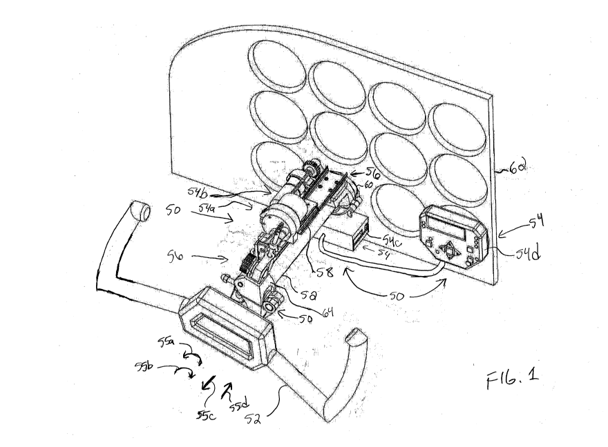
[25] FIG. 1 shows a perspective view of an autopilot system 50, according to
an
embodiment of the invention. The autopilot system 50 is releasably mounted to
a
control yoke 52 in a cabin of an aircraft (here a Cessna 172). Although, the
autopilot
system 50 is shown releasably mounted to a control yoke 52, the autopilot
system 50
may be releasably mounted to an aircraft's stick if the aircraft includes a
stick in lieu of a
control yoke 52. The autopilot system 50 includes an autopilot control circuit
54 to
control an aspect of the aircraft's flight, and a device 56 to releasably
mount the
autopilot control circuit 54 to the aircraft's control yoke 52. As shown here
in FIG. 1 and
discussed in greater detail in conjunction with FIGS. 3 and 7 ¨ 19, the
autopilot system
50 includes two control circuits 54a and 54b; however, the autopilot system 50
may
include fewer or more control circuits as desired. Control circuit 54a
controls the
aircraft's roll during flight by controlling the rotation of the yoke 52 in
the directions
indicated by the arrows 55a and 55b. Control circuit 54b controls the
aircraft's pitch
during flight by controlling the movement of the yoke 52 in the directions
indicated by
the arrows 55c and 55d. And, each of the control circuits 54a and 54b are
governed by
the autopilot system's control unit 54c and user interface unit 54d.
[26] The device 56 includes a frame 58 that holds the control circuits 54a and
54b, a
first coupler 60 to releasably mount the frame 58 to the aircraft's airframe
62 (here an
instrument panel of the Cessna 172 which is fixed to the portion of the
airframe that
defines the aircraft's cabin), and a second coupler 64 to releasably mount the
frame 58
to the control yoke 52. When the device 56 is releasably mounted to the
aircraft's
instrument panel 62 and control yoke 52, and when the autopilot control
circuits 54a and
54b are engaged, each control circuit 54a and 54b receives a signal from the
control
unit 54c to either hold the device's frame 58 still to maintain the aircraft's
current flight
trajectory, or move the devices frame 58 to move the control yoke 52 to change
the
aircraft's current flight trajectory.
[27] With the autopilot system 50, one may convert an aircraft that does not
include
an autopilot system into one that does, and use the autopilot system 50 to
control one
or more aspects of the aircraft's flight. This allows a pilot to enhance the
safety of
CA 02965494 2017-04-21
WO 2016/105650 PCT/US2015/055576
his/her flight by reducing his/her workload and fatigue, especially during
longer flights,
and improve flight time and fuel efficiency. The autopilot system 50 may also
be used
to keep an aircraft's wings level when the pilot needs both hands to look up
reference
information. This is particularly important while flying in unstable air,
which requires the
pilot to maintain an uninterrupted force on the aircraft's flight controls to
maintain a
heading. In addition, in aircraft that already have an autopilot system, the
additional
autopilot system 50 can provide a redundant autopilot system should the
original
autopilot system not work properly.
[28] With the device 56 one can releasably mount one or more autopilot control
circuits 54 to a control yoke and/or stick of a variety of different aircraft
to quickly and
easily control one or more aspects of the aircraft's flight. This allows a
pilot to use the
same autopilot system 50 in a variety of different aircraft. For example, a
pilot may rent
an aircraft that does not include an autopilot system, and safely fly the
aircraft a long
distance by releasably mounting the portable autopilot system 50 in the
aircraft's cabin.
Then, for the return trip, the pilot may rent a different aircraft that also
does not include
an autopilot system, and safely fly the aircraft by releasably mounting the
same portable
autopilot system 50 in the aircraft's cabin, enjoying the benefits stated
above.
[29] FIG. 2 shows a perspective view of the device 56 shown in FIG. 1,
according to
an embodiment of the invention. The device 56 includes a frame 58 for holding
an
autopilot control circuit. The device 56 also includes a first coupler 60 that
is releasably
fastened to the frame 58 and is operable to releasably mount the frame 58 to
an
aircraft's airframe. The first coupler 60 is discussed in greater detail in
conjunction with
FIGS. 3, 4A and 4B. The 'device 56 also includes a second coupler 64 that is
also
releasably fastened to the frame 58 and is operable to releasably mount the
frame 58 to
an aircraft's flight control component. In addition to the second coupler 64
being shown
in FIG. 2 and discussed below, the second coupler 64 is shown in FIGS. 4C and
4D,
which should also be referred during the discussion below.
[30] The frame 58 may be configured as desired to hold an autopilot control
circuit
and move the second coupler 64, and thus an aircraft's flight control
component (control
yoke and/or stick), relative to the first coupler 60. For example, in this and
other
6
CA 02965494 2017-04-21
WO 2016/105650 PCT/1JS2015/055576
embodiments, the frame 58 includes a first portion 70 having an end 72 and a
second
portion 74 having an end 76. The first portion's end 72 is configured to
releasably
fasten to the first coupler 60 as shown in FIG. 3 and discussed in greater
detail in
conjunction with FIG. 3. The first portion 70 is configured to hold the second
portion 74
such that the second portion 74 may slide in either of the directions
indicated by the
arrows 78a and 78b, but not move in the directions indicated by the arrow 80
relative to
the first portion. The second portion's end 76 is configured to pivot in the
directions
indicated by the arrows 82a and 82b about the axis 84. In this configuration,
when the
second coupler 64 is releasably mounted to the yoke 52 (FIG. 1) and the second
portion's end 76 pivots about the axis 84, the second coupler 64, and thus the
yoke 52,
rotate about the axis 86, or the axis of the shaft of the yoke. And, when the
frame's
second portion 74 slides relative to the frame's first portion 70, the second
coupler 64,
and thus the yoke 52, move along the axis 86 closer to or farther away from
the first
coupler 60.
[31] The second coupler 64 may be releasably fastened to the frame 58 in any
desired manner. For example, in this and other embodiments, the coupler 64 is
pinned
to the end 76 of the frame's second portion. More specifically, the device 56
includes a
pin 88 that a receptacle 90 of the second coupler 64 receives and that a
collar 92 of the
end of the frame's second portion surrounds. The receptacle 90 and collar 92
are sized
to fit around the pin 88 such that the pin 88 does not wobble inside each of
them, but
slides along the axis 94 relative to each. Configured in this manner, the
collar 92 slides
relative to the pin 88 along the axis 94 as the end 76 pivots about the axis
84, so that
the second coupler 64 may freely rotate about the axis 86 in response. If the
collar 92
didn't slide relative to the pin 88, then the rotation of the end 76 would try
to move the
second coupler across the axis 86 in addition to rotating it about the axis
86, and thus
bind up the motion of the second coupler 64.
[32] Another benefit of this configuration is that one may quickly and easily
releasably
fasten the frame 58 to the second coupler 64 after the coupler 64 is mounted
to the
yoke 52 by aligning the collar 92 with the receptacle 90 and then inserting
the pin 88
through the collar 92 and into the receptacle 90. Or, one may releasably
fasten the
frame 58 to the second coupler 64 before releasably mounting the second
coupler 64 to
7
CA 02965494 2017-04-21
WO 2016/105650
PCT/US2015/055576
the yoke 52. In either case, after the device 56 has been releasably mounted
to the
yoke 52, one can quickly and easily release the second coupler 64, and thus
the yoke
52, from the frame 58 by withdrawing the pin 88 from the receptacle 90. This
allows
one to quickly disengage the autopilot system 50 (FIG. 1) from the aircraft to
take
control of the aircraft's flight trajectory. In addition, the pin 88 includes
a breakaway
portion 96 (shown in FIG. 40) that is sized to break in shear when a
predetermined
shear load is applied to the pin 88 to provide the pilot another mechanism for
disengaging the autopilot system 50. With the pin's breakaway portion 96, one
may
simply grab the yoke 52 and push/pull and/or rotate the yoke 52 with enough
force to
= cause the breakaway portion 96 to break, and thus release the second
coupler 64 from
the frame 58. =
[33] Still referring to FIG. 2, the second coupler 64 may be configured as
desired to
releasably mount the frame 58 to the aircraft's flight control component. For
example, in
this and other embodiments, the coupler 64 includes a clamp 98 having two jaws
100a
and 100b. The jaw 100a is pivotally attached to the jaw 100b, so that one may
spread
= apart the jaws 100a and 100b to insert the shaft of the yoke 52 or stick.
A bolt 102 is
slidably attached to the jaw 110b and threadingly attached to the jaw 100a. To
releasably mount the second coupler 64 to the shaft of the yoke 52, the bolt
102 is
moved relative to the jaw 100b by rotating the cam 106 (FIG. 4C). This urges
the jaw
100a toward the jaw 100b and generates a squeezing force on the shaft. To
allow the
clamp 98 to hold a variety of different shafts each having a different shaft
diameter, the
bolt 102 may be threadingly moved relative to the jaw 100a to move the cam 106
toward or away from the jaw 100a, before rotating the cam 106 to force the jaw
100a
toward the jaw 100b. The jaw 100b also includes a clevis 108 through which a
pin 110
passes to pivotally connect the clamp 98 to the body 109 that houses the
receptacle 90.
Pivotally connected in this manner, the clamp 98 may be clocked (such as 90
degrees)
relative to the clamp's position shown in FIG. 2 to releasably mount the
second coupler
64 to a stick whose shaft is more vertical than the shaft of the yoke 52 (FIG.
1). To lock
the clamp 98 in a desired position, one rotates the knob 112 (FIG. 4C) to
generate
friction between the clevis 108 and the body 109.
8
CA 02965494 2017-04-21
=
WO 2016/105650
PCT/1JS2015/055576
=
[34] FIG. 3 shows a perspective view of the device 56 shown in FIGS.1 and 2,
according to an embodiment of the invention. The device 56 includes a first
coupler 60
that is releasably fastened to the frame 58 and is operable to releasably
mount the
frame 58 to an aircraft's airframe. In addition to the first coupler 60 being
shown in FIG.
3 and discussed below, the first coupler 60 is shown in FIGS. 4A and 4B, which
should
also be referred to during the discussion below. As shown in FIG. 3, the
device's frame
58 holds the autopilot control circuit 54a that controls an aircraft's roll,
and the autopilot
control circuit 54b that controls the aircraft's pitch.
[35] The first coupler 60 may be releasably fastened to the frame 58 in any
desired
manner. For example, in this and other embodiments, the first coupler 60
includes a
receptacle 116 configured to hold the end 72 of the frame's first portion 70,
and a
depression 117 configured to hold a ball 118 located in the end 72. More
specifically,
the first coupler 60 includes two depressions located in the receptacle 116,
and the end
72 of the frame's first portion 70 includes two balls 118. When the end 72 of
the frame's
first portion 70 is releasably fastened to the first coupler 60, the body 120
lies in the
receptacle 116, the lip 122 lies in the groove 124, and each of the balls 118
extend into
a respective one of the depressions 117. A spring disposed inside the body 120
urges
each of the balls 118 into their respective depression 117. To release the
frame's first
portion 70, and thus the frame 58 from the first coupler 60, one may pull the
end 72 of
the frame's first portion 70 up away from the first coupler 60.
[36] The first coupler 60 may be configured as desired to releasably mount the
frame
58 to the aircraft's airframe. For example, in this and other embodiments the
first
coupler 60 includes a clamp having a first half 126 and a second half 128. The
first and
second halves 126 and 128 are sized and configured to hold a specific portion
of a
specific aircraft's airframe.. For example, the first and second halves 126
and 128, are
sized and configured to clamp onto a portion of the instrument panel of a
Cessna 172.
To allow the device 56 to be releasably mounted to other aircraft models or
other
locations in a Cessna 172, a first coupler that is similar to but different
than the first
coupler 60 may be releasably fastened to the frame 58. The first half 126
includes the
receptacle 116, and a plug 130 and contacts 132 (seven shown but only one
labeled for
clarity) to couple the control circuits 54a and 54b to the autopilot system's
control unit
9
CA 02965494 2017-04-21
WO 2016/105650 PCT/1JS2015/055576
=
54c (FIG. 1). The first half 126 and the second half 128 each includes a boss
134 that
prevents the first coupler 60, and thus the frame 58 from moving relative to
the aircraft's
airframe. In this manner, the autopilot control circuits 54a and 54b may move
the end
76 without moving the first coupler 60 or the frame 58 in the opposite
direction. Two
pins 136a and 136b inserted through knuckles 138a and 138b in each of the
halves 126
and 128 fasten the first half 126 to the second half 128.
[37] Still referring to FIG. 3, the autopilot control circuit 54a may be
configured as
desired. For example, in this and other embodiments, the autopilot control
circuit 54a
includes an electric motor 140 mounted to the frame's second portion 74. The
motor's
output shaft 142 is coupled to the end 76 such that rotating the output shaft
142 causes
the end 76 to pivot about the axis 84 (FIG. 2). The motor 140 receives signals
from the
autopilot system's control unit 54c that direct the motor to rotate its output
shaft 142.
The autopilot control circuit 54a also includes an aileron position and force
sensor 144
that tells the control unit 54c the position of the ailerons based on the
position of the
yoke 52, and the amount force required on the yoke 52 to hold the ailerons at
the
position. Knowing this information before one disengages the autopilot control
circuit
54a helps one avoid sudden changes in the aircraft's flight trajectory as one
takes over
control of the aircraft. The autopilot control 54a is discussed in greater
detail in
conjunction with FIGS. 7 ¨ 15.
[38] The autopilot control circuit 54b may also be configured as desired. For
example, in this and other embodiments, the autopilot control circuit 54b
includes a
motor 146 coupled to a lead screw 148 via a gear 150. The autopilot control
circuit 54b
also includes a carrier 152 operatively coupled to the lead screw 148 such
that as the
lead screw 148 rotates, it moves the carrier 152 in one of the two directions
indicated by
the arrows 154a and 154b. The carrier 152 is mounted to the second portion 74
of the
frame 58, and the motor 146 and lead screw 148 are mounted to the first
portion 70 of
the frame 58. Thus, when the lead screw 148 rotates clockwise, the carrier 152
moves
in the direction indicated by the arrow 154b, which moves the frame's second
portion 74
in the same direction. This in turn moves the second coupler 64, and thus the
yoke 52,
towards the first coupler 60. Similarly, when the lead screw 148 rotates
counterclockwise, the carrier 152 moves in the direction indicated by the
arrow 154a,
CA 02965494 2017-04-21
WO 2016/105650 PCT/US2015/055576
which moves the second portion 74 in the same direction. This in turn moves
the
second coupler 64, and thus the yoke 52, away from the first coupler 60. To
rotate the
lead screw 148, the motor 146 rotates its output shaft 156, which rotates the
gear 150.
The autopilot control circuit 54b also includes an elevator position and force
sensor 158
that tells the control unit 54c the position of the aircraft's elevator based
on the position
of the yoke 52, and the amount force required on the yoke 52 to hold the
elevators at
the position. Knowing this information before one disengages the autopilot
control
circuit 54b helps one avoid sudden changes in the aircraft's flight trajectory
as one takes
over control of the aircraft.
[39] FIGS. 5 and 6, together show a perspective view of a portion of a device
160 of
an autopilot system, according to another embodiment of the invention. The
device 160
is similar to the device 56 shown and discussed in conjunction with FIGS. 1 ¨
4D,
except that the second coupler 162 is releasably fastened to the end 164 of a
second
portion 166 of a frame 168 via a pin 170 that may slide in a slot 172 of a
yoke 174. In
this configuration, the pin's longitudinal axis 176 is substantially
perpendicular to the slot
172. In this manner, the second coupler may be releasably fastened to the
frame 168
quickly and easily, and unlike the device 56, one does not have to align a
collar 92 (FIG.
2) with a receptacle 90 (FIG. 2) before inserting a pin 88 (FIG. 2).
[40] FIG. 7 shows a perspective view of the autopilot system 50 shown in FIG.
1,
according to an embodiment of the invention. FIG. 8 shows a schematic view of
a
portion of the autopilot system 50 in FIG. 7, according to an embodiment of
the
invention. The autopilot system 50 includes control circuits 54a and 54b, a
control unit
54c, a user interface 54d, and a power coupler 54e that may be inserted into a
cigarette
lighter and convey power to the control circuits 54a and 54b, the control unit
54c, and
the user interface 54d. Control circuit 54a controls the aircraft's roll
during flight and is
discussed in greater detail in conjunction with FIGS. 10 ¨ 15. Control circuit
54b
controls the aircraft's pitch. during flight and is discussed in greater
detail in conjunction
with FIGS. 16 ¨ 19. The control unit 54c governs the control circuits 54a and
54b, and
is discussed in greater detail in conjunction with FIGS. 9 ¨ 19. The user
interface 54d
allows one to input information into the autopilot system 50 and displays
information
from the autopilot system 50. The user interface 54d is discussed in greater
detail in
11
CA 02965494 2017-04-21
WO 2016/105650 PCT/US2015/055576
conjunction with FIGS. 9 19. The autopilot system 50 also includes cables 200
for
transmitting signals and/or power to components of the autopilot system 50. In
addition,
the autopilot system 50 may be coupled to a global positioning system (GPS)
202 (not
shown in FIG. 7 but shown in FIG. 8) and receive and use information from the
GPS to
help control the aircraft's flight trajectory.
[41] FIG. 9 shows a plan view of the user interface 54d, according to an
embodiment
of the invention, and a perspective view the control unit 54c, also according
to an
embodiment of the invention.
[42] The user interface 54d may be configured as desired to allow one to
provide the
control unit 54c information and to receive and display information from the
control unit
54c. For example, in this and other embodiments, the user interface 54d
includes an
alphanumeric display 332, enunciator lights 330, keys, and ambient light
sensor 329.
The control unit 54c scans for a key entry, measures an ambient light signal
from the
sensor 329, and sets light intensity of the enunciators 330 and display 332
for optimal
visibility under the current lighting condition. The alphanumeric display 332
displays
relevant parameters and messages to the pilot which are applicable to the
current
operation of the autopilot system 50. The enunciators 330 include LEDs, and
provide
status and mode information. In addition to displaying the relevant parameters
for the
current operation of the autopilot system 50, the user interface 54d may
display two
critical flight performance parameters ¨ ground speed and altitude of the
aircraft. To do
this, a GPS unit 202 (FIG. 8) is connected to the control unit 54c. By
displaying these
two flight parameters, the autopilot system 50 provides an important safety
backup in
case of failure of the aircraft's respective instruments.
[43] Still referring to FIG. 9, the control unit 54c may be configured as
desired to
govern the control circuits 54a and 54b. For example, in this and other
embodiments,
the control unit 54c includes electronics necessary to measure flight and
environmental
parameters, power the motors 140 (FIG. 3) and 146 (FIG. 3), decipher GPS data,
send
display data to the user interface 54d, and receive key actuations from the
user
interface 54d as well as measure ambient light and set display backlight
intensity. In
12
CA 02965494 2017-04-21
WO 2016/105650 PCT/US2015/055576
addition, the control unit 54c may measure the torque and position of one or
more of the
motors 140 and 146. The'control unit 54c also provides memory and computing
power
to execute one or more algorithms that control the autopilot system's
performance.
Such algorithms include algorithms for controlling roll and pitch of the
aircraft during
flight, performing self diagnostics, and performing the logic required for the
various
modes of operation and exception analysis and handling. The control unit 54c
includes
an inertial measurement unit, which is suspended to isolate it from mechanical
vibrations. The inertial measurement unit includes miniature gyroscopes,
accelerometers, magnetic compass sensors, and an altimeter sensor. The control
unit
54c also includes four connectors: 1) a power connector 320 to receive the
power
coupler 54e (FIG. 7) and provide aircraft power to the autopilot system 50, 2)
a user
interface connector 321 to provide power and communication to the user
interface 54d,
3) an actuation apparatus connector 323 to provide power and communication to
the
motors 140 and 146, and 4) an external GPS connector 322 to provide power and
communication to an optional GPS unit 202 (FIG. 8).
[44] The control unit 54c may be mounted anywhere as desired. For example, in
this
and other embodiments, the control unit 54c is mounted to the bottom of the
device 56
(FIGS. 2 and 3). In other embodiments, the control unit 54c may be mounted to
another
location which is referenced to the airframe. Because the control unit 54c
uses an
inertial measurement unit to orient the aircraft in space, the control unit
54c should be
positioned at a stable location in relation to the airframe.
[45] FIG. 10 shows a flowchart of the control unit's process for operating the
control
circuit 54a, according to an embodiment of the invention. Each of FIGS. 11 ¨
14 shows
a schematic view of a portion of the control circuit 54a that corresponds to
one of four
operational modes, each according to an embodiment of the invention. And FIG.
15
shows an example of a flight plan that the autopilot system 50 uses the
control circuit
54a to follow (or navigate), according to an embodiment of the invention.
[46] The control unit 54c monitors the user interface 54d for information that
changes
the input parameters of the control circuit 54a, such as a change in
operational modes;
13
CA 02965494 2017-04-21
WO 2016/105650 PCT/US2015/055576
or a change in a parameter within the operational mode currently in use, such
as a
change in a desired aileron deflection or desired rate of turn (ROT) typically
expressed
in degrees per second (cIpS). The control unit 54c then invokes the
appropriate
algorithm to effect the desired control of the aircraft.
[47] The control circuit 54a includes a servo circuit 356 (FIG. 11) that
applies force to
the yoke 52, and includes the motor 140 (FIG. 3). The control circuit 54a also
includes
four selectable operational (or NAV) modes: 1) Manual mode; 2) Wing Leveler (W-
LVLR) mode; 3) Heading Hold (M-HDNG) mode; and 4) GPS Tracking (G-TRAK) mode.
To select one of the four modes, one simply pushes the NAV key 331 of the user
interface 54d until one of the lights 330 corresponding to the desired mode is
on. When
none of the lights 330 is on, then this indicates that the Manual mode is in
operation.
Each of the operation modes includes an algorithm that determines when and to
what
extent the aircraft's ailerons should be moved to provide a desired flight
trajectory. After
this has been determined, the control unit 54c uses the servo circuit 356 to
power the
motor 140 to effect the change in the position of the aircraft's ailerons. The
Manual
operational mode is discussed in greater detail in conjunction with FIG. 11.
The Wing
Leveler (W-LVLR) operational mode is discussed in greater detail in
conjunction with
FIG. 12. The Heading Hold (M-HDNG) operational mode is discussed in greater
detail
in conjunction with FIG. 13. And the GPS Tracking (G-TRAK) operational mode is
discussed in greater detail in conjunction with FIG. 14.
[48] Referring to FIG. 10, the flowchart shows a roll axis control loop that
the control
unit 54c executes as frequently as desired. For example, in this and other
embodiments, the control unit 54c executes the loop every 40 milliseconds to
determine
whether or not the deflection of the aircraft's ailerons should be changed. On
entry of
the Update roll axis control loop 3200, a selection tree made up of three
tests 3300,
3600 and 4100, determines the roll axis or NAV mode. If it is in Manual mode,
then the
right key 345 (FIG. 9) and left key 346 (FIG. 9) of the user interface 54d
increase 5200
or decrease 5100 the ailerons' desired deflection amount respectively. Here,
increasing
the ailerons' deflection means that the right aileron pivots upward relative
to the wing
while the left aileron pivots downward relative to the wing; and decreasing
the ailerons'
14
CA 02965494 2017-04-21
WO 2016/105650
PCT/US2015/055576
deflection means that the right aileron pivots downward while the left aileron
pivots
upward. If no key entry, then no adjustment is made to the aileron's
deflection. Next,
the deflection amount is converted and applied to the servo circuit 356
(Discussed in
greater detail in conjunction with FIG. 11), which uses the Roll gain 1250
adhering to a
set of limits 1240. If the selection tree indicates that the Wing Leveler (W-
LVLR) mode
is currently selected, then the control unit 54c checks for input via the keys
of the user
interface 54d. The Right key 345 (FIG. 9) increases 4900 the desired ROT, and
the Left
key 346 (FIG. 9) decreases 3400 the desired ROT value. Here, increasing ROT
while
turning to the right makes the plane turn steeper to the right, and decreasing
ROT while
turning to the right makes the plane turn shallower to the right. But,
increasing the ROT
while turning to the left makes the plane turn shallower to the left, and
decreasing the
ROT while turning to the left makes the plane turn steeper to the left. If the
measured
ROT value is greater than the desired ROT value 4800, then the aileron's
desired
deflection is decreased 5100, otherwise it is increased. The new desired
deflection is
then converted and applied to the servo circuit 356 to change the aileron's
deflection,
which again uses the Roll gain 1250 adhering to a set of limits 1240. If the
selection
tree indicates that the Heading Hold mode (M-HDNG) is currently selected, then
the
control unit 54c checks first to see if the mode is suspended 4000 (suspended
is a
secondary mode which is manifested as W-LVLR mode). If it is suspended then
the
Wing Leveler (W-LVLR) mode is invoked. If not suspended, then the measured
heading (from the GPS or compass sensor) is compared to the desired heading
3700.
If the measured heading is right of the desired heading then the control unit
decreases
ailerons' desired deflection amount 5100 to turn the aircraft to the left,
else it turns it to
the right by increasing the ailerons' desired deflection 5200. The new desired
deflection
is then converted and applied to the servo circuit 356 to change the aileron's
deflection,
which again uses the Roll gain 1250 adhering to a set of limits 1240, and the
desired
heading updated. If the selection tree indicates the GPS Tracking (G-TRAK)
mode is
selected, then the control unit 54c checks first to see if the mode is
suspended 4200. If
it is, then the Wing Leveler mode is invoked. If it isn't, then it calculates
an appropriate
= intercept angle 4300 from the cross-track error 4400 and ground speed
4500 provided
by the GPS. With this intercept angle and the desired course 3600 also
provided by the
CA 02965494 2017-04-21
WO 2016/105650 PCT/US2015/055576
GPS, it can calculate the desired ground track 3800 that the aircraft must fly
in order to
intercept or maintain the desired ground track corresponding to the GPS flight
plan.
The latter is equal to the desired course when the aircraft is on course
(cross-track error
= ONM). Next, the aircraft'.s actual ground track is compared to the desired
ground track
4700, and if the actual ground track, as provided by the GPS, is greater than
the desired
ground track, then it decreases the ailerons' desired deflection amount 5100
to turn the
aircraft to the left to merge into the desired ground track. Else, it turns it
to the right by
increasing the ailerons' desired deflection 5200. The new desired deflection
is then
converted and applied to the servo circuit 356 to change the aileron's
deflection, which
again uses the Roll gain 1250 adhering to a set of limits 1240. Unless in
Manual mode,
all turn rates are proportional to the amount of error between the desired and
actual
headings or ROTs, and do not exceed 3.5 degrees per second (dps) to the left
or the
right. A smaller error results in a slower turn. Thus, the speed of the motor
140 while
making corrections in heading is proportional to the amount of error in
performing the
comparisons of desired and measured ROT 4800, heading 3700 and ground track
4700.
[49] Referring to FIG. 11, the servo circuit 356 may be configured and invoked
as
desired. For example, in this and other embodiments, the servo circuit 356 is
invoked
when any of the four operational modes are selected and the control unit 54c
determines that the aileron's deflection should be changed. When in the Manual
operational mode this is done by pressing the Left key 346 or the Right key
345 of the
user interface 54d. The input information is connected numerically to the
input of the
servo circuit 356, which directs the motor 140 to rotate the yoke 52 to effect
the desired
change in the aileron's deflection.
[50] In this and other embodiments, the objective of the servo circuit 356 is
to set the
deflection of the aircraft's ailerons 399 to a pre-determined desired
deflection amount
358. The input to this control loop is a numerical desired deflection amount
358 and the
effect is an actual deflection of the aircraft's ailerons 399 to that amount.
It is
implemented in both algorithmic and electromechanical means, comprising a Roll
servo
difference function 357, a Roll motor drive algorithm 362, Roll motor drive
electronics
16
CA 02965494 2017-04-21
WO 2016/105650
PCT/1JS2015/055576
398, and the motor 140. The difference between the numeric value of the
desired
deflection amount 358 and the ailerons' deflection as sensed by the ailerons'
deflection
sensor 144 corresponds to the ailerons' deflection error 361, which is
converted to a
proportional drive value by the Roll motor drive algorithm 362. The result of
the
algorithm is amplified by the Roll motor drive electronics 398, which output
is
interconnected to the motor 140, and powers the motor 140. As discussed in
conjunction with FIGS. 2 and 3, the motor rotates the yoke 52 (FIG. 1), and
the ailerons'
deflection angle 371 is measured by the ailerons deflection sensor 144.
[51] Referring to FIG. 12, the rate-of-turn (ROT) control loop 369 may be
configured
as desired. It may be invoked to turn the aircraft at a desired rate of turn,
or it may be
= invoked to keep the aircraft's wings level (an ROT equal to zero) when
the Wing Leveler
(W-LVLR) operational mode is selected. One may enter a desired ROT value 359
by
pressing the Left key 346 (FIG. 9) or the Right key 345 (FIG. 9) of the User
interface
unit 54d. This control loop 369 automatically sets the ailerons deflection
angle 371 as
necessary for turning the aircraft at the desired ROT value 359, or for
maintaining level
wings or zero ROT.
[52] In this and other embodiments, the objective of this control loop 369 is
to
automatically set the deflection of the aircraft's ailerons to an amount which
will result in
an aircraft turning rate equal to the Desired ROT value 359 as set by the
control unit
54c. The mechanism of this loop is implemented in both algorithmic and
electrical
circuitry means, comprising an ROT gyroscope 363, a GPS derived ROT 364, an
ROT
combiner 366, a Low pass digital filter 365, an ROT difference function 423, a
Roll gain
370 factor, a Roll converter 354, a Roll axis limiter 355, and the servo
circuit 356 (FIG.
11). To determine the present rate of turn (ROT) of the aircraft, the ROT
combiner 366,
algorithmically combines two ROT sources, the ROT gyroscope 363 data and the
GPS
derived ROT 364. The ROT is filtered using Low pass digital filter 365, and
then
subtracted from the desired ROT value by the ROT difference function 423. The
result
is a numeric ROT error 353 which is then scaled by a predetermined Roll gain
370, and
converted by the Roll converter 354, to a proportional deflection value, which
is then
numerically limited by the Roll axis limiter 355 and fed as ailerons' desired
deflection
17
CA 02965494 2017-04-21
WO 2016/105650
PCT/11S2015/055576
amount 358 to the Roll servo circuit 356. The servo circuit 356 then sets the
ailerons
= deflection angle 371 to the desired deflection amount 358. The limiter
355 imposes
several predefined limits, which include ROT limit, roll rate limit, roll
angle limit and
ailerons deflection limit.
[53] Note that setting a deflection is different than setting a rate. When
entering an
aileron deflection as in Manual mode, the aircraft may continue to roll, until
such
deflection is reversed or neutralized. When setting a rate of turn (ROT),
however, the
= ailerons 399 are automatically and continuously adjusted by the autopilot
system 50
resulting in a predictable turn rate.
[54] Still referring to FIG. 12, in this and other embodiments, the default
value of the
Roll gain 370 is predetermined for each aircraft type and model, to provide
optimal
performance of the roll axis control system in terms of both, stability and
responsiveness. This value is automatically loaded when selecting aircraft
type and
= model, by using the setup facility provided in the autopilot system 50.
This value may
be edited by the pilot as to modify the roll axis performance as preferred by
the pilot.
This value is saved in non-volatile memory, and is reloaded anytime the
autopilot
system 50 powers up. Reducing the default Roll gain 370 results in a more
sluggish
aircraft response in turns, as well as lower tracking accuracy, while
increasing it results
in a quicker response, or jittery under-damped response or even hunting or
oscillations
in roll attitude.
[55] Referring to FIG. 13, the heading control loop 372 may be configured as
desired
to maintain a desired heading or ground track 373. Here, heading and ground-
track are
interchangeable. Typically, heading is used when referencing a magnetic
compass,
and ground-track is used when referencing GPS. The heading control loop 372
may be
invoked by manually steering the aircraft to a desired heading, then selecting
the
Heading Hold mode. The heading control loop 372 may also be invoked while the
system 50 is in the W-LVLR mode by pressing the NAV key 331 (FIG. 9) of the
user
interface 54d to enter the Heading Hold (M-HDNG) operational mode. At the
instance
the control loop 372 is invoked the current aircraft heading as indicated by
the on-board
18
CA 02965494 2017-04-21
WO 2016/105650 PCT/11JS2015/055576
compass sensor 375 and, if available, the current ground-track 374 from a GPS,
is
stored as desired heading 373. If, while in the Heading Hold (M-HDNG) mode,
the
aircraft is steered to a desired heading by pushing one or more of the right
and left keys
345 and 346, respectively, then the Heading Hold (M-HDNG) mode is suspended.
Suspended mode is similar to but not identical to W-LVLR mode. It is a W-LVLR
mode
with the capacity to set a turn rate value rather than keep the wings leveled.
Once the
right and/or left keys 345 and 346, respectively, are pushed while in the W-
LVLR, M-
HDNG or G-TRAK modes, the system 50 enters NAV suspended mode and the right
and left keys 345 and 346, respectively, adjust a turn rate value. Suspended
mode
behaves the same in the W-LVLR, M-HDNG or G-TRAK modes. While suspended, the
previously selected mode's LED flashes. When exiting the suspended mode the
system
50 resumes the operating mode W-LVLR, M-HDNG or G-TRAK that it was suspended
from. If the resumed mode is the W-LVLR mode, then the wings are leveled (ROT
= 0).
If the resumed mode is the M-HDNG mode, then the current aircraft heading as
indicated by the on-board compass sensor 375 and, if available, the current
ground-
track 374 from a GPS, is stored as desired heading 373. If the resumed mode is
the
G-TRAK mode, then the system 50 resumes tracking the flight plan¨that is, re-
intercepts and tracks the desired course in the plan.
[56] In this and other embodiments, the objective of this control loop 372 is
to
automatically set the deflection of the Aircraft's ailerons 399 to an amount
which will
result in the aircraft flying a desired heading or ground track 373. This is
done by
automatically turning the aircraft at a desired ROT value 359 which will
minimize any
directional error. The mechanism of this loop 372 is implemented in both
algorithmic
and electrical circuitry means, comprising a heading measuring component,
which
includes a source selector 377, which automatically selects the current
aircraft heading
from an on-board compass sensor 375 or when available, the current ground-
track 374
from a GPS. The measured heading or ground-track 378 is subtracted from the
desired
heading or ground track 373 using the difference function 376. This yields a
numeric
representation of the direction error 379. The error 379 is then scaled and
converted by
the ROT translator 318, to the desired ROT value 359, which is applied to the
ROT
control loop 369 (FIG. 12). The ROT control loop 369 automatically sets an
ailerons
19
CA 02965494 2017-04-21
WO 2016/105650
PCT/US2015/055576
deflection angle 371 to effect the required turn to return to or maintain the
desired
heading or ground-track 373, minimizing the amount of the direction error 379.
= [57] Still referring to FIG. 13, in this and other embodiments, when
Heading Hold (M-
HDNG) operational mode is selected while a GPS is unavailable, the source
selector
377 will automatically select the compass sensor 375 for directional data.
This will
result in the nose of the aircraft pointing in the approximate direction of
the desired
heading or ground track 373, subjecting the actual flight path over the ground
to wind
drift error. An additional error in this case may be compass heading error,
which could
be several degrees. When GPS ground-track 374 is available, it will be
automatically
selected by the source selector 377, and the aircraft will fly a precise
ground track which
is negligibly affected by wind drift. In such a case, the aircraft will
automatically point
into the wind at an angle proportional to the wind speed and direction. The
stronger the
cross wind component, the more it will point towards the wind, resulting in
negligible
ground track error.
[58] Referring to FIG. 14, the GPS tracking control loop 381 may be configured
as
desired to track a GPS flight plan or GoTo. It may be invoked when the GPS
Tracking
(G-TRAK) operational mode is selected. An active GPS flight plan, or route,
may
include several waypoints and segments, and each may have a different desired
course
383 (FIG. 15). One may temporarily suspend GPS tracking and deviate from the
flight
plan by using the Left key 346 (FIG. 9) or the Right key 345 (FIG. 9) of the
user
interface 54d, to steer the aircraft to a desired heading. While suspended,
pressing the
= NAV key 331 (FIG. 9) will restore flight plan tracking. Input to the GPS
tracking control
loop 381 includes data received from the GPS while a flight plan or GoTo is
active. The
autopilot system 50 follows the flight plan course by automatically adjusting
the ailerons
deflection angle 371, steering a precise ground track, and turning to a new
desired
course at designated waypoints. If, while tracking, GPS flight plan data from
the GPS is
corrupt or lost, then the autopilot system 50 automatically reverts to the
Wing Leveler
(W-LVLR) operational mode to maintain level wings and the current heading.
Once
GPS data is restored, the autopilot system 50 automatically resumes tracking
the flight
plan by intercepting and following it.
CA 02965494 2017-04-21
WO 2016/105650 PCT/1JS2015/055576
[59] In this and other embodiments, the objective of this control loop 381 is
to
automatically set the deflection of the aircraft's ailerons to an amount which
will result in
the aircraft flying a pre-programmed direction, or desired ground track 390,
to intercept
and track the desired course 383. The GPS tracking control loop 381 inputs
include a
ground speed 382, a desired course 383, and a cross-track error 384. The
outcome is
ground-track 374 (FIG. 13), which corresponds with great accuracy to the
desired
ground-track 390. The control loop 381 is implemented in both algorithmic and
electromechanical means, comprising an intercept calculator 385, algorithms,
and the
heading control loop 372, discussed in conjunction with FIG. 13. It is
necessary to have
a GPS with an active flight-plan or GoTo to utilize the GPS tracking control
loop 381. A
desired ground-track 390 is calculated by the intercept calculator 385 the
value of which
is applied to the heading control loop 372 as a desired heading or ground-
track 373
input, which, by means of ailerons deflection, steers the aircraft to fly the
desired
ground-track 390. The Intercept calculator 385 algorithm calculates a varying
desired
ground-track 390 which is the most efficient path for the aircraft to acquire
and maintain
the desired course 383. It also calculates a threshold cross-track error
beyond which
the desired ground-track 390 is at a 45-degree (intercept) angle relative to
the desired
course 383. Below the threshold the desired ground-track 390 diminishes
asymptotically, as the aircraft gets closer to the desired course 383. This
threshold
cross-track distance is proportional to the ground speed 382 by a
predetermined
relation.
[60] Still referring to FIG. 14, in this and other embodiments, the desired
ground-track
390, is calculated by the intercept calculator 385, using the desired course
383, aircraft
ground speed 382, and aircraft distance from intended course, or cross-track
error 384.
The resulting desired ground track 390 is applied as the desired heading or
ground
track 373 to the heading control loop 372 to automatically control aircraft
ground-track
374. If the aircraft is a distance from the desired course 383 that exceeds a
pre-calculated cross-track error 384 threshold value, which is proportional to
the ground
speed of the aircraft, the desired ground-track 390 is set at a 45
(intercept) angle
relative to the desired course. For smaller deviations, the intercept angle
asymptotically
diminishes to 0 (on course). In a multi segment flight plan, the aircraft is
automatically
21
CA 02965494 2017-04-21
WO 2016/105650
PCT/US2015/055576
turned by the autopilot system 50 to a new course segment at the specified way-
point in
a smooth and controlled manner. This produces a smooth and efficient course
intercept, accurate course tracking, and pleasant turns.
= [61] Referring to FIG. 15, an example of a GPS flight plan is shown. It
includes flight
plan origin 392 point, two waypoints, and a flight plan destination 386. Each
of the three
segments of this flight plan has a different desired course 383 angle. At the
indicated
position of the aircraft 393 it follows a desired ground-track 390
corresponding to a 45
degree intercept 391 relative to the desired course 383, which is the first
segment of the
flight plan. At its position in the 45 degrees intercept 391 region, it will
hold this
ground-track heading because its distance from the intended course (its Cross-
track
error 384) is greater than the intercept threshold 388. The desired ground
track 390 line
indicates that once the aircraft 393 is within the intercept threshold 388, it
flies an
asymptotic intercept 389 ground-track, with diminishing intercept angle, until
its
ground-track coincides with the desired course 383. Once on course, it will be
tracking
394 the desired course 383, meaning the desired ground-track will coincide
with the
desired course 383. When it arrives at waypoint B 387, the autopilot system 50
automatically turns the aircraft 393 to the new desired course 383,
corresponding to the
second segment of the flight plan. The intercept threshold 388 is directly
proportional to
the aircraft ground speed. With newer technology GPS units, data provided to
the
autopilot system 50 allows it to perform a fly-by ground track, where it will
begin the turn
to a new flight plan segment heading slightly before it arrives at the
changeover
waypoint, rounding the turn for a smoother, more efficient flight performance.
The point
at which it begins the turn depends on the ground speed of the aircraft and
the amount
of turn required. Older GPS units only provide a fly-over type performance,
where the
turn to a new flight plan segment heading follows arrival at the waypoint. The
autopilots
system 50 is capable of handling both fly-by and fly-over methods.
[62] FIG. 16 shows a flowchart of the control unit's process for operating the
control
circuit 54b, according to an embodiment of the invention. Each of FIGS. 17 ¨
19 shows
a schematic view of a portion of the control circuit 54b that corresponds to
one of three
operational modes, each according to an embodiment of the invention.
22
CA 02965494 2017-04-21
WO 2016/105650
PCT/US2015/055576
[63] The control unit 54c monitors the user interface 54d for information that
changes
the input parameters of the control circuit 54b, such as a change in
operational modes;
or a change in a parameter within the operational mode currently in use, such
as a
change in a desired elevator deflection or desired rate of change in altitude.
The control
unit 54c then invokes the appropriate algorithm to effect the desired control
of the
aircraft.
[64] The control circuit 54b includes a servo circuit 401 (FIG. 17) that
applies force to
the yoke 52, and includes the motor 146 (FIG. 3). The control circuit 54b also
includes
three selectable operational (or ALT) modes: 1) Manual mode; 2) Altitude Hold
(HOLD)
mode; and 3) Suspended Altitude Hold mode. Each of the operation modes
includes an
algorithm that determines when and to what extent the aircraft's elevator
should be
moved to provide a desired flight trajectory. After this has been determined,
the control
= unit 54c uses the servo circuit 401 to power the motor 146 to effect the
change in the
position of the aircraft's elevator. The Manual operational mode is discussed
in greater
detail in conjunction with FIG. 17. The Altitude Hold (HOLD) operational mode
is
discussed in greater detail in conjunction with FIG. 18. And the Suspended
Altitude
Hold operational mode is discussed in greater detail in conjunction with FIG.
19.
[65] Referring to FIG. 16, the flowchart shows a pitch axis control loop that
the control
= unit 54c executes as frequently as desired. For example, in this and
other
embodiments, the control unit 54c executes the loop every 80 milliseconds to
determine
whether or not the deflection of the aircraft's elevator should be changed. On
entry of
the Update pitch axis control loop 8400, a selection is made between Manual
and
Altitude Hold (HOLD) modes 8500. If in Manual mode, and input from the Up key
344
(FIG. 9) is detected 8600, the desired elevator deflection amount is increased
1190,
else if input from the Down key 339 (FIG. 9) is detected 9300 then the
deflection
amount is decreased 1200. An increase in elevator deflection implies tilting
the
aircraft's nose up. If no key input is detected, no change is made, and the
event is
terminated 9500. Following each increase or decrease in elevator deflection
1190,
1200, the pitch motor drive level and direction is calculated 1210 and scaled
by pitch
gain 1220 while considering the limits in pitch angle 1230 and presently set
elevator
23
CA 02965494 2017-04-21
WO 2016/105650 PCT/1JS2015/055576
deflection 1800. Then, power is applied to the motor 146. If not in Manual
mode 8500,
but rather in Suspended Altitude Hold 900 mode, and input from the Up key 344
is
detected 9200, then the desired vertical speed is increased by 100 feet per
minute (fpm)
8900 (or some other value which is deemed appropriate as preselected by the
pilot). If
input from the Down key 339 is detected 9600, then the vertical speed is
reduced by
100 fpm 9100. If no key input is detected, the currently set desired vertical
speed is
maintained. Then, the desired vertical speed is compared 8700 with the
measured
vertical speed, and if the measured vertical speed is greater, then the
desired deflection
amount is decreased 1200 proportionally to the difference of these two values;
else it is
increased 1190 proportionally. The deflection amount is then converted to an
appropriate motor drive level 1210 by applying pitch gain 1220 and comparing
to the
current elevator deflection 1800, while observing pitch angle limit 1230. Then
the
calculated amount of power is applied to the motor 146 (FIG. 3). If the
Altitude Hold
mode is not suspended 900, then the measured altitude is compared to the pre-
determined desired altitude 9000. If the measured altitude (present altitude
of the
aircraft) is greater than the desired altitude, then the elevator deflection
amount is
decreased 1200 in order to lower the aircraft nose and descend to the desired
altitude.
Otherwise, the elevator deflection amount is increased 1190 in order to climb
back to
the desired altitude. The speed of the motor 146 while correcting altitudes or
climb
rates is proportional to the amount of error detected in performing the
comparisons of
altitude 9000 and climb rates 8700 respectively.
[66] Referring to FIG. 17, the servo circuit 401 may be configured and invoked
as
desired. For example, in this and other embodiments, the servo circuit 401 is
invoked
when any of the three operational modes are selected and the control unit 54c
determines that the elevator's deflection should be changed. When in the
Manual
operational mode this is done by pressing the Up key 344 (FIG. 9) or the Down
key 339
(FIG. 9) of the user interface 54d. The input information is connected
numerically to the
input of the servo circuit 401, which directs the motor 146 to move the yoke
52 to effect
the desired change in the elevator's deflection.
24
CA 02965494 2017-04-21
WO 2016/105650 PCT/US2015/055576
[67] In this and other embodiments, the objective of the servo circuit 401 is
to set the
deflection of the aircraft's elevator 409 to a pre-determined desired
deflection amount
403. The input to this control loop is a numerical desired deflection amount
403 and its
effect is to set the deflection of the aircraft's elevator 409 to that amount.
It is
implemented in both algorithmic and electromechanical means, comprising a
Pitch
servo difference function 402, a Pitch motor drive algorithm 405, Pitch motor
drive
electronics 408, and the motor 146. The difference between the numeric value
of the
desired deflection amount 403 and the elevator's actual deflection angle 406,
which is
measured by the elevator position sensor 158 (FIG. 3), provides a numeric
representation of the pitch deflection error 404, which is converted to a
proportional
motor drive value by the Pitch motor drive algorithm 405. The numerical result
of the
algorithm is amplified by the Pitch motor drive electronics 408, whose output
powers
motor 146. As discussed in conjunction with FIGS. 2 and 3, the motor 146 moves
the
yoke 52 (FIG. 1), and the elevator's deflection angle 406 is measured by the
elevator
deflection sensor 158.
[68] Referring to FIG. 18, the altitude hold control loop 417 may be
configured as
desired to maintain the aircraft at a constant altitude. It may be invoked
when the
Altitude Hold (HOLD) operational mode is selected. In this and other
embodiments, the
objective of this control loop 417 is to automatically adjust the deflection
of the aircraft's
elevator 409 to an amount which will result in the aircraft maintaining a
desired altitude
415. The desired altitude 415 may be determined and stored in the autopilot
system's
memory when the pilot selects the Altitude Hold mode by pressing the ALT key
343
(FIG. 9) of the User interface 54d while the pitch axis system is in Manual
mode.
Alternatively, the desired altitude 415 may be determined and stored in the
autopilot
system's memory when the pilot exits the Suspended Altitude Hold mode (or
vertical
speed control) by pressing the ALT key 343 of the user interface 54d while in
vertical
speed control mode. The mechanism of this loop 417 is implemented in both
algorithmic
and electrical circuitry means, comprising, a Altimeter sensor 410, GPS
altitude 411
data, an Altitude source selector 412, an Altitude difference function 422, a
Pitch axis
gain 416, a Pitch converter 421, a Pitch axis limiter 418 and a Pitch axis
servo control
loop 401. The aircraft's present altitude 413 is determined from either, the
GPS altitude
CA 02965494 2017-04-21
WO 2016/105650
PCT/US2015/055576
411 data, if such is available, or from the Altimeter sensor 410, as
automatically
selected by the Altitude source selector 412. The aircraft's present altitude
413 is
subtracted from the desired altitude 415 by the Altitude difference function
422, resulting
in an Altitude error 414, which is scaled by a predetermined Pitch gain 416
and
converted by the Pitch converter 421 to a proportional elevator deflection
value. This is
then numerically limited by the Pitch axis limiter 418 and input to the servo
circuit 401 as
a desired elevator deflection amount 403. As previously described, the servo
circuit 401
= sets the elevator deflection angle 420 to the desired elevator deflection
amount 403.
The Pitch axis limiter 418 imposes several predefined limits, which includes a
rate of
pitch limit, a pitch angle limit, and an elevator deflection angle limit.
[69] Still referring to FIG. 18, the default value of the Pitch axis gain 416
is
predetermined for each aircraft type and model to provide optimal performance
of the
altitude hold control loop 417 in terms of both, stability and response time.
This value is
= automatically loaded when selecting aircraft type and model, by using the
setup facility
provided in the autopilot system 50. This value may be edited by the pilot to
modify the
performance as preferred by the pilot. This value is saved in non-volatile
memory and
reloaded anytime the autopilot system 50 powers up. Reducing the default Pitch
axis
gain 416 results in a more sluggish aircraft response to climb and descend
commands,
as well as lower altitude setting accuracy, while increasing it results in a
quicker
response, or jittery under-damped response or even hunting or oscillations in
pitch
attitude. By default, while in Altitude Hold mode, the autopilot system 50
limits climb
and descent rates to 700 fpm. The pilot may modify this rate by editing it
using the
setup operation of the autopilot system 50.
[70] Referring to FIG. 19, the suspend altitude hold control loop 419 may be
configured as desired and may be invoked when the Altitude Hold (HOLD)
operational
mode is selected. While in Altitude Hold mode, the pilot may suspend this mode
and
set a desired vertical speed 425 to commence a climb or a descent. To enter
this
Suspended Altitude Hold mode (vertical speed mode) the pilot presses either
the Up
key 344 or the Down key 339 of the user interface 54d while in Altitude Hold
mode. The
user interface 54d indicates the Suspended Altitude Hold mode, as well as
displaying
26
CA 02965494 2017-04-21
WO 2016/105650
PCT/US2015/055576
the target or desired vertical speed. While in the suspended mode the vertical
speed is
determined by use of the Up key 344, which increases the vertical speed, and
the Down
key 345 which reduces the vertical speed. Repeated key entry of these keys
adjusts
the vertical speed incrementally in steps of 100 fpm. While in the suspended
mode,
pressing the ALT key 343 exits the suspended mode, setting the desired
altitude 415
value to the aircraft's present altitude 413, and resuming normal Altitude
Hold operation.
[71] In this and other embodiments, the objective of this control loop 419 is
to set a
desired vertical speed 425. It automatically adjusts the deflection of
aircraft's elevator
409 to an amount resulting in the desired vertical speed 425. The amount of
the
desired vertical speed 425 is manually entered by the pilot while in Suspended
Altitude
Hold mode. This loop 419 is implemented in both algorithmic and electrical
circuitry
means, comprising an Altimeter sensor 410, GPS altitude 411 data, an Altitude
source
selector 412, a Vertical speed difference function 427, a Vertical speed gain
429, a
Vertical speed converter 430, a Pitch axis limiter 418 and a Pitch axis servo
control loop
401. The aircraft's present altitude 413 is selected from either, the GPS
altitude 411
source, if available, or from the Altimeter sensor 410. The aircraft's present
altitude 413
is then converted to the aircraft's present vertical speed 424 by the
differentiator 426.
The vertical speed 424 is then subtracted from desired vertical speed 425 by
the
Vertical speed difference function 427. The result is the error in vertical
speed 428,
which is then scaled by a predetermined Vertical speed gain 429 and converted
by the
Vertical speed converter 430 to a proportional elevator deflection value. This
is then
input to the Pitch axis limiter 418 resulting in a desired elevator deflection
amount 403
which is translated to Elevator deflection angle 420 by the servo circuit 401.
This
moves the aircraft's elevator 409 to the desired elevator deflection amount
403. The
Pitch axis limiter 418 imposes several predefined limits; including rate of
pitch limit, pitch
= angle limit, and elevator deflection angle limit.
[72] The control circuit 54b also includes trim enunciators 330 (FIG. 9) to
indicate
elevator trim requirements. They indicate to the pilot the direction of the
trim adjustment
to be made. When in trim, both, the up arrow 330a and the down arrow 330b trim
indicators are extinguished, meaning no trimming is required. When the up
arrow 330a
= 27
CA 02965494 2017-04-21
WO 2016/105650
PCT/US2015/055576
enunciator is illuminated, it is an indication to the pilot to trim for nose
up attitude. When
the down arrow 330a enunciator is illuminated, it is a sign that a nose down
trim control
is required. The pilot should trim until both lights are turned off. If a
significant elevator
trim adjustment is required, the respective enunciators will flash.
[73] Trimming the aircraft elevator is important for several reasons. The
motor 146
has limited force and is not capable of applying enough force to make large
pitch
attitude adjustments. When the elevator is properly trimmed, a small force
from the
= motor 146 is usually required to maintain a target altitude. Also, if the
aircraft is properly
trimmed, disengaging the autopilot system 50 will not result in an unpleasant,
abrupt
pitch change.
[74] The trim indicator operates whenever the autopilot system 50 is engaged.
The
Control unit 54c measures the trim status and sets the enunciators 330a and
330b in
the user Interface 54d accordingly. The trim sense system measures the amount
and
= direction of force applied by the control circuit 54b onto the yoke 52
(FIG. 1). The
linkage between the elevator actuation mechanisms may include a flexible
element,
such as a spring or some other flexible element, such as a rubber band, that
responds
to force by stretching proportionally to the force applied. A position sensor
translates
the amount of movement into an electrical signal. This signal is then measured
at a rate
of three times per second by the control unit 54c. In this and other
embodiments, the
trim sensor can be mounted on the linear slide part of the autopilot system,
or at
another position on the autopilot system 50 to provide an electrical or
mechanical
indication of the amount of force applied to the elevator. Such other
embodiments can
be mechanical indicators that express this force by a moving pointer or dial.
A further
embodiment can also include a load cell to measure the force, which may be
provided
electrical excitation, and whose signal may be measured by the control unit
54c.
[75] Since elevator trim is essential, a redundant detection system is
included, which
also provides an indirect indication of elevator trim. In this embodiment and
others, the
elevator motor currents are measured in both, elevator down and up movements.
These
currents reflect the torque, or force applied. The control unit 54c performs
these
28
CA 02965494 2017-04-21
WO 2016/105650 PCT/1JS2015/055576
measurements at a rate of three times per second and saves the averaged values
of
these currents. Comparing the magnitudes of the currents as well as their
difference
provides an indication of trim requirements. This method serves as the backup
for the
sensor apparatus, and is utilized if the latter is diagnosed to be erroneous.
[76] Each of FIGS. 20 ¨ 23 shows a flowchart of a process that the autopilot
system
shown in FIGS. 1 and 7 ¨ 19 follows, each according to an embodiment of the
invention.
FIG. 20 shows a process that the control unit 54c uses to scan the user
interface 54d
for information input via the user interface's keys. FIG. 21 shows three
different
processes that the control unit 54c uses to update inertial information of the
aircraft.
FIG. 22 shows a process that the control unit 54c uses to update information
on the
aircraft's roll, and another process that the control unit 54c uses to update
information
on the aircraft's pitch. FIG. 23 shows a process that the control unit 54c
uses to update
information on the aircraft's altitude and flight direction.
[77] The preceding discussion is presented to enable a person skilled in the
art to
make and use the invention. Various modifications to the embodiments will be
readily
apparent to those skilled in the art, and the generic principles herein may be
applied to
other embodiments and applications without departing from the spirit and scope
of the
present invention. Thus, the present invention is not intended to be limited
to the
embodiments shown, but is to be accorded the widest scope consistent with the
principles and features disclosed herein.
=
29