Note: Descriptions are shown in the official language in which they were submitted.
CA 02965503 2017-04-21
WO 2016/065335 PCT/US2015/057240
NEGATIVE-PRESSURE THERAPY WITH PNEUMATICALLY-ACTUATED
INSTILLATION
TECHNICAL FIELD
[0001] The invention set forth in the appended claims relates generally to
tissue
treatment systems and more particularly, but without limitation, to
apparatuses and methods
for providing negative-pressure therapy with instillation of topical treatment
solutions.
BACKGROUND
[0002] Clinical studies and practice have shown that reducing pressure in
proximity
to a tissue site can augment and accelerate growth of new tissue at the tissue
site. The
applications of this phenomenon are numerous, but it has proven particularly
advantageous
for treating wounds. Regardless of the etiology of a wound, whether trauma,
surgery, or
another cause, proper care of a wound is important to the outcome. Treatment
of wounds or
other tissue with reduced pressure may be commonly referred to as "negative-
pressure
therapy," but is also known by other names, including "negative-pressure wound
therapy,"
"reduced-pressure therapy," "vacuum therapy," "vacuum-assisted closure," and
"topical
negative-pressure," for example. Negative-pressure therapy may provide a
number of
benefits, including migration of epithelial and subcutaneous tissues, improved
blood flow,
and micro-deformation of tissue at a wound site. Together, these benefits can
increase
development of granulation tissue and reduce healing times.
[0003] There is also widespread acceptance that cleansing a tissue site can be
highly
beneficial for new tissue growth. For example, a wound can be washed out with
a stream of
liquid solution, or a cavity can be washed out using a liquid solution for
therapeutic purposes.
These practices are commonly referred to as "irrigation" and "lavage"
respectively.
"Instillation" is another practice that generally refers to a process of
slowly introducing fluid
to a tissue site and leaving the fluid for a prescribed period of time before
removing the fluid.
For example, instillation of topical treatment solutions over a wound bed can
be combined
with negative-pressure therapy to further promote wound healing by loosening
soluble
contaminants in a wound bed and removing infectious material. As a result,
soluble bacterial
burden can be decreased, contaminants removed, and the wound cleansed.
1
CA 02965503 2017-04-21
WO 2016/065335 PCT/US2015/057240
[0004] While the clinical benefits of negative-pressure therapy and
instillation are
widely known, the cost and complexity of negative-pressure therapy can be a
limiting factor
in its application, and the development and operation of negative-pressure
systems,
components, and processes continues to present significant challenges to
manufacturers,
healthcare providers, and patients.
2
CA 02965503 2017-04-21
WO 2016/065335 PCT/US2015/057240
BRIEF SUMMARY
[0005] New and useful systems, apparatuses, and methods for providing negative-
pressure therapy with instillation of topical treatment solutions are set
forth in the appended
claims. Illustrative embodiments are also provided to enable a person skilled
in the art to
make and use the claimed subject matter.
[0006] For example, an apparatus is described herein that may comprise an
exudate
container, a solution source, and an instillation regulator that can be
pneumatically-actuated.
The instillation regulator may be coupled to the exudate container and to the
solution source,
and negative pressure from a negative-pressure source can actuate the
instillation regulator.
In some embodiments, for example, a negative-pressure source may be configured
for a
negative-pressure interval and a venting interval, and the instillation
regulator can be
configured to draw instillation solution from the solution source during a
negative-pressure
interval and to instill the solution to a dressing during a venting interval.
[0007] In more particular example embodiments, the instillation regulator may
have a
solution inlet port, a solution outlet port, and a negative-pressure port. The
solution inlet port
may be fluidly coupled to a solution source, and the solution outlet port may
be fluidly
coupled to a dressing. The negative-pressure port may be fluidly coupled to a
negative-
pressure source, which can provide negative pressure through the negative-
pressure port to
actuate the instillation regulator.
[0008] In some example embodiments, the instillation regulator may include a
piston
disposed within a housing. The piston may partition the housing into a first
chamber and a
second chamber. The solution inlet port may be fluidly coupled to the solution
source and to
the first chamber. The solution outlet port may be fluidly coupled to a
dressing and to the
first chamber. The negative-pressure port may fluidly couple a negative-
pressure source to
the second chamber, so that negative pressure applied to the second chamber
through the
negative-pressure port during a negative-pressure interval can actuate the
piston. For
example, if negative pressure is applied to the second chamber, the pressure
differential
across the piston can move the piston within the housing, increasing the
volume of the first
chamber and decreasing the volume of the second chamber. An increase in the
volume of the
first chamber can decrease the pressure in the first chamber, drawing
instillation solution
from the solution source through the solution inlet port and into the first
chamber. If the
pressure in the second chamber is increased, such as during a venting
interval, the pressure
3
CA 02965503 2017-04-21
WO 2016/065335 PCT/US2015/057240
differential across the piston can reverse the movement of the piston to
decrease the volume
of the first chamber and increase the volume of the second chamber. Decreasing
the volume
of the first chamber can increase the pressure in the first chamber, expelling
instillation
solution from the first chamber through the solution outlet port. Check valves
can be coupled
to the solution inlet port and the solution outlet port to prevent drawing
fluid through the
solution outlet port and expelling fluid through the solution inlet port.
[0009] In some embodiments, the instillation regulator may be disposed within
an
exudate container. For example, the instillation regulator may be integrally
molded with an
exudate container or may be mounted to an interior surface of an exudate
container. In yet
other example embodiments, the instillation regulator may be configured for
coupling
between an exudate container and a negative-pressure source.
[0010] In some embodiments, instillation solution may be managed as an
ancillary to
an exudate container, but in other embodiments the instillation solution may
be managed
integrally to the exudate canister. For example, in some embodiments, a
solution source may
be externally mounted on an exudate container, but in other example
embodiments, a solution
source may be disposed within an exudate container.
[0011] An apparatus having some or all of these illustrative features may also
be used
in a system for providing negative-pressure therapy with instillation of
topical treatment
solutions. For example, a system for treating a tissue site with negative-
pressure and
instillation therapy may include a dressing, an exudate container, and a
negative-pressure
source fluidly coupled to the dressing and the exudate container. The system
may also
include a source of instillation solution. An instillation regulator may be
fluidly coupled to
the solution source and to the negative-pressure source. Negative pressure
from the negative-
pressure source can actuate the instillation regulator to draw solution from
the solution
source. Venting the negative pressure can actuate the instillation regulator
to instill the
solution to the dressing.
[0012] In yet other embodiments, a method for treating a tissue site with
negative
pressure and topical instillation solution is also describe. For example, a
dressing may be
applied to the tissue site and coupled to a negative-pressure source. An
instillation regulator
may also be fluidly coupled to the negative-pressure source and to the
dressing. A source of
instillation solution may be coupled to the instillation regulator. Solution
may be drawn to
the instillation regulator from the solution source during a negative-pressure
interval, and
4
CA 02965503 2017-04-21
WO 2016/065335 PCT/US2015/057240
solution may be instilled from the instillation regulator to the dressing
during a venting
interval.
[0013] Objectives, advantages, and a preferred mode of making and using the
claimed
subject matter may be understood best by reference to the accompanying
drawings in
conjunction with the following detailed description of illustrative
embodiments.
CA 02965503 2017-04-21
WO 2016/065335 PCT/US2015/057240
BRIEF DESCRIPTION OF THE DRAWINGS
[0014] Figure 1 is a functional block diagram of an example embodiment of a
therapy
system that can provide negative-pressure therapy and instillation in
accordance with this
specification;
[0015] Figure 2 is a perspective view illustrating additional details that may
be
associated with some example embodiments of an instillation regulator in the
therapy system
of Figure 1;
[0016] Figures 3A-3B are assembly views illustrating additional details that
may be
associated with some embodiments of the instillation regulator of Figure 2;
[0017] Figure 4 is a top view illustrating additional details that may be
associated
with some embodiments of the instillation regulator of Figure 2;
[0018] Figure 5A is a cross-section of the instillation regulator shown in
Figure 4
taken along line 5A-5A;
[0019] Figure 5B is a cross-section of the instillation regulator shown in
Figure 4
taken along line 5B-5B;
[0020] Figure 6 is a perspective view illustrating additional details of
another
example embodiment of an instillation regulator that may be associated with
the therapy
system of Figure 1;
[0021] Figures 7A-7B are assembly views illustrating additional details that
may be
associated with some embodiments of the instillation regulator of Figure 6;
[0022] Figure 8 is a top view illustrating additional details that may be
associated
with some embodiments of the instillation regulator of Figure 6;
[0023] Figure 9A is a cross-section of the instillation regulator shown in
Figure 8
taken along line 9A-9A;
[0024] Figure 9B is a cross-section of the instillation regulator shown in
Figure 8
taken along line 9B-9B;
[0025] Figure 9C is a cross-section of the instillation regulator shown in
Figure 8
taken along line 9C-9C;
[0026] Figure 10 is a schematic diagram illustrating an example embodiment of
a
fluid management system comprising an instillation regulator disposed within
an exudate
container;
6
CA 02965503 2017-04-21
WO 2016/065335 PCT/US2015/057240
[0027] Figure 11 is a schematic diagram illustrating another example
embodiment of
a fluid management system comprising the instillation regulator of Figure 10
disposed within
an exudate container;
[0028] Figure 12 is a schematic diagram illustrating another alternative
embodiment
of a fluid management system;
[0029] Figure 13 is a schematic diagram illustrating another alternative
embodiment
of a fluid management system;
[0030] Figure 14 is a schematic diagram illustrating yet another example
embodiment
of a fluid management system; and
[0031] Figure 15 is a schematic diagram illustrating additional details that
may be
associated with some embodiments of a fluid management system.
7
CA 02965503 2017-04-21
WO 2016/065335 PCT/US2015/057240
DESCRIPTION OF EXAMPLE EMBODIMENTS
[0032] The following description of example embodiments provides information
that
enables a person skilled in the art to make and use the subject matter set
forth in the appended
claims, but may omit certain details already well-known in the art. The
following detailed
description is, therefore, to be taken as illustrative and not limiting.
[0033] The example embodiments may also be described herein with reference to
spatial relationships between various elements or to the spatial orientation
of various
elements depicted in the attached drawings. In general, such relationships or
orientation
assume a frame of reference consistent with or relative to a patient in a
position to receive
treatment. However, as should be recognized by those skilled in the art, this
frame of
reference is merely a descriptive expedient rather than a strict prescription.
[0034] Figure 1 is a simplified block diagram of an example embodiment of a
therapy system 100 that can provide negative-pressure therapy with
instillation of topical
treatment solutions in accordance with this specification. The therapy system
100 may
include a dressing and a negative-pressure source. For example, a dressing 102
may be
fluidly coupled to a negative-pressure source 104, as illustrated in Figure 1.
A regulator, such
as a pressure regulator 106, may also be fluidly coupled to the dressing 102
and the negative-
pressure source 104. A dressing may include a cover and a tissue interface.
The dressing
102, for example, may include a cover 108 and a tissue interface 110. The
therapy system
100 may also include an exudate container, such as a container 112, coupled to
the dressing
102 and to the negative-pressure source 104.
[0035] The therapy system 100 may also include a source of instillation
solution.
For example, a solution source 114 may be fluidly coupled to the dressing 102,
as illustrated
in the example embodiment of Figure 1. A second regulator, such as an
instillation regulator
116, may be fluidly coupled to the solution source 114 and the dressing 102.
In some
embodiments, the instillation regulator 116 may also be pneumatically coupled
to the
negative-pressure source 104, as illustrated in the example of Figure 1. The
instillation
regulator 116 may also be integrated with the container 112 in some
embodiments to provide
a single, disposable product.
[0036] In general, components of the therapy system 100 may be coupled
directly
or indirectly. For example, the negative-pressure source 104 may be directly
coupled to the
pressure regulator 106 and indirectly coupled to the dressing 102 through the
pressure
8
CA 02965503 2017-04-21
WO 2016/065335 PCT/US2015/057240
regulator 106. In some embodiments, components may be coupled by virtue of
physical
proximity, being integral to a single structure, or being formed from the same
piece of
material. Coupling may also include mechanical, thermal, electrical, or
chemical coupling
(such as a chemical bond) in some contexts.
[0037] Components may be fluidly coupled to each other to provide a path for
transferring fluids (i.e., liquid and/or gas) between the components. In some
embodiments,
for example, components may be fluidly coupled through a tube. A "tube," as
used herein,
broadly refers to a tube, pipe, hose, conduit, or other fluid conductor with
one or more lumina
adapted to convey fluid between two ends. Typically, a tube is an elongated,
cylindrical
structure with some flexibility, but the geometry and rigidity may vary. A
fluid conductor
may also be integrally molded into a component in some embodiments.
[0038] In operation, the tissue interface 110 may be placed within, over, on,
or
otherwise proximate to a tissue site. The cover 108 may be placed over the
tissue interface
110 and sealed to tissue near the tissue site. For example, the cover 108 may
be sealed to
undamaged epidermis peripheral to a tissue site. Thus, the dressing 102 can
provide a sealed
therapeutic environment proximate to a tissue site, substantially isolated
from the external
environment, and the negative-pressure source 104 can reduce the pressure in
the sealed
therapeutic environment. Negative pressure applied across a tissue site
through the tissue
interface 110 in the sealed therapeutic environment can induce macro-strain
and micro-strain
in the tissue site, as well as remove exudate and other fluid from the tissue
site, which can be
collected in the container 112 and disposed of properly.
[0039] The fluid mechanics of using a negative-pressure source to reduce
pressure
in another component or location, such as within a sealed therapeutic
environment, can be
mathematically complex. However, the basic principles of fluid mechanics
applicable to
negative-pressure therapy and instillation are generally well-known to those
skilled in the art.
[0040] In general, fluid flows toward lower pressure along a fluid path. Thus,
the
term "downstream" typically implies something in a fluid path relatively
closer to a source of
negative pressure or further away from a source of positive pressure;
conversely, the term
"upstream" implies something relatively further away from a source of negative
pressure or
closer to a source of positive pressure. Similarly, it may be convenient to
describe certain
features in terms of fluid "inlet" or "outlet" in such a frame of reference,
and the process of
reducing pressure may be described illustratively herein as "delivering,"
"distributing," or
9
CA 02965503 2017-04-21
WO 2016/065335 PCT/US2015/057240
"generating" reduced pressure, for example. This orientation is generally
presumed for
purposes of describing various features and components herein.
[0041] The term "tissue site" in this context broadly refers to a wound or
defect
located on or within tissue, including but not limited to, bone tissue,
adipose tissue, muscle
tissue, neural tissue, dermal tissue, vascular tissue, connective tissue,
cartilage, tendons, or
ligaments. A wound may include chronic, acute, traumatic, subacute, and
dehisced wounds,
partial-thickness burns, ulcers (such as diabetic, pressure, or venous
insufficiency ulcers),
flaps, and grafts, for example. The term "tissue site" may also refer to areas
of any tissue that
are not necessarily wounded or defective, but are instead areas in which it
may be desirable to
add or promote the growth of additional tissue. For example, negative pressure
may be used
in certain tissue areas to grow additional tissue that may be harvested and
transplanted to
another tissue location.
[0042] "Negative pressure" generally refers to a pressure less than a local
ambient
pressure, such as the ambient pressure in a local environment external to a
sealed therapeutic
environment provided by the dressing 102. In many cases, the local ambient
pressure may
also be the atmospheric pressure at which a tissue site is located.
Alternatively, negative
pressure may be a pressure less than a hydrostatic pressure associated with
tissue at the tissue
site. Unless otherwise indicated, values of pressure stated herein are gauge
pressures.
Similarly, references to increases in negative pressure typically refer to a
decrease in absolute
pressure, while decreases in negative pressure typically refer to an increase
in absolute
pressure.
[0043] A negative-pressure source, such as the negative-pressure source 104,
may
be a reservoir of air at a negative pressure, or may be a manual or
electrically-powered device
that can reduce the pressure in a sealed volume, such as a vacuum pump, a
suction pump, a
wall suction port available at many healthcare facilities, or a micro-pump,
for example. A
negative-pressure source may be housed within or used in conjunction with
other
components, such as sensors, processing units, alarm indicators, memory,
databases,
software, display devices, or user interfaces that further facilitate negative-
pressure therapy.
While the amount and nature of negative pressure applied to a tissue site may
vary according
to therapeutic requirements, the pressure is generally a low vacuum, also
commonly referred
to as a rough vacuum, between -5 mm Hg (-667 Pa) and -500 mm Hg (-66.7 kPa).
Common
therapeutic ranges are between -75 mm Hg (-9.9 kPa) and -300 mm Hg (-39.9
kPa). In some
CA 02965503 2017-04-21
WO 2016/065335 PCT/US2015/057240
embodiments, negative pressure may be applied intermittently or periodically,
with intervals
of negative-pressure and intervals of venting or positive-pressure.
[0044] The tissue interface 110 can be generally adapted to contact a tissue
site.
The tissue interface 110 may be partially or fully in contact with a tissue
site. If a tissue site
is a wound, for example, the tissue interface 110 may partially or completely
fill the wound,
or may be placed over the wound. The tissue interface 110 may take many forms,
and may
have many sizes, shapes, or thicknesses depending on a variety of factors,
such as the type of
treatment being implemented or the nature and size of a tissue site. For
example, the size and
shape of the tissue interface 110 may be adapted to the contours of deep and
irregular shaped
tissue sites. In some embodiments, the tissue interface may be provided in a
spiral cut sheet.
Moreover, any or all of the surfaces of the tissue interface 110 may have an
uneven, coarse,
or jagged profile that can induce micro-strains and stresses at a tissue site.
[0045] In some embodiments, the tissue interface 110 may be a manifold. A
"manifold" in this context generally includes any substance or structure
providing a plurality
of pathways adapted to collect or distribute fluid across a tissue site. For
example, a manifold
may be adapted to receive negative pressure from a source and distribute
negative pressure
through multiple apertures across a tissue site, which may have the effect of
collecting fluid
from across a tissue site and drawing the fluid toward the source. In some
embodiments, the
fluid path may be reversed or a secondary fluid path may be provided to
facilitate distributing
fluid across a tissue site.
[0046] In some illustrative embodiments, the pathways of a manifold may be
interconnected to improve distribution or collection of fluids across a tissue
site. For
example, cellular foam, open-cell foam, reticulated foam, porous tissue
collections, and other
porous material such as gauze or felted mat generally include pores, edges,
and/or walls
adapted to form interconnected fluid pathways. Liquids, gels, and other foams
may also
include or be cured to include apertures and fluid pathways. In some
illustrative
embodiments, a manifold may be a porous foam material having interconnected
cells or pores
adapted to distribute negative pressure across a tissue site. The foam
material may be either
hydrophobic or hydrophilic. The pore size of a foam material may vary
according to needs of
a prescribed therapy. For example, in some embodiments, the tissue interface
110 may be a
foam having pore sizes in a range of 400-600 microns. The tensile strength of
the tissue
interface 110 may also vary according to needs of a prescribed therapy. For
example, the
tensile strength of a foam may be increased for instillation of topical
treatment solutions. In
11
CA 02965503 2017-04-21
WO 2016/065335 PCT/US2015/057240
one non-limiting example, the tissue interface 110 may be an open-cell,
reticulated
polyurethane foam such as GranuFoam dressing available from Kinetic Concepts,
Inc. of
San Antonio, Texas; in other embodiments the tissue interface 110 may be an
open-cell,
reticulated polyurethane foam such as a VeraFlo foam, also available from
Kinetic
Concepts, Inc., of San Antonio, Texas.
[0047] In an example in which the tissue interface 110 may be made from a
hydrophilic material, the tissue interface 110 may also wick fluid away from a
tissue site,
while continuing to distribute negative pressure to the tissue site. The
wicking properties of
the tissue interface 110 may draw fluid away from a tissue site by capillary
flow or other
wicking mechanisms. An example of a hydrophilic foam is a polyvinyl alcohol,
open-cell
foam such as V.A.C. WhiteFoam dressing available from Kinetic Concepts, Inc.
of San
Antonio, Texas. Other hydrophilic foams may include those made from polyether.
Other
foams that may exhibit hydrophilic characteristics include hydrophobic foams
that have been
treated or coated to provide hydrophilicity.
[0048] In some embodiments, the tissue interface 110 may be constructed from
bioresorbable materials. Suitable bioresorbable materials may include, without
limitation, a
polymeric blend of polylactic acid (PLA) and polyglycolic acid (PGA). The
polymeric blend
may also include without limitation polycarbonates, polyfumarates, and
capralactones. The
tissue interface 110 may further serve as a scaffold for new cell-growth, or a
scaffold material
may be used in conjunction with the tissue interface 110 to promote cell-
growth. A scaffold
is generally a substance or structure used to enhance or promote the growth of
cells or
formation of tissue, such as a three-dimensional porous structure that
provides a template for
cell growth. Illustrative examples of scaffold materials include calcium
phosphate, collagen,
PLA/PGA, coral hydroxy apatites, carbonates, or processed allograft materials.
[0049] In some embodiments, the cover 108 may provide a bacterial barrier and
protection from physical trauma. The cover 108 may also be constructed from a
material that
can reduce evaporative losses and provide a fluid seal between two components
or two
environments, such as between a therapeutic environment and a local external
environment.
The cover 108 may be, for example, an elastomeric film or membrane that can
provide a seal
adequate to maintain a negative pressure at a tissue site for a given negative-
pressure source.
In some example embodiments, the cover 108 may be a polymer drape, such as a
polyurethane film, that is permeable to water vapor but impermeable to liquid.
Such drapes
typically have a thickness in the range of 25-50 microns. For permeable
materials, the
12
CA 02965503 2017-04-21
WO 2016/065335 PCT/US2015/057240
permeability generally should be low enough that a desired negative pressure
may be
maintained.
[0050] An attachment device may be used to attach the cover 108 to an
attachment
surface, such as undamaged epidermis, a gasket, or another cover. The
attachment device
may take many forms. For example, an attachment device may be a medically-
acceptable,
pressure-sensitive adhesive that extends about a periphery, a portion, or an
entirety of the
cover 108. In some embodiments, for example, some or all of the cover 108 may
be coated
with an acrylic adhesive having a coating weight between 25-65 grams per
square meter
(g.s.m.). Thicker adhesives, or combinations of adhesives, may be applied in
some
embodiments to improve the seal and reduce leaks. Other example embodiments of
an
attachment device may include a double-sided tape, paste, hydrocolloid,
hydrogel, silicone
gel, or organogel.
[0051] In some embodiments, the dressing 102 may also include a fluid
interface
configured to fluidly couple the negative-pressure source 104 to the sealed
therapeutic
environment formed by the cover 108. In some embodiments, the fluid interface
may include
a flange portion that couples to the cover 108 and a portion that fluidly
couples to a tube 120.
In one exemplary embodiment, the fluid interface may be a T.R.A.C.0 Pad or
Sensa
T.R.A.C.0 Pad available from Kinetic Concepts, Inc. of San Antonio, Texas. In
other
exemplary embodiments, a tube may be inserted through the cover 108. Such a
fluid
interface can allow negative pressure to be delivered to the sealed
therapeutic environment.
For example, a fluid interface can provide a fluid conductor through the cover
108 to the
tissue interface 110. In some embodiments, a fluid interface can also provide
more than one
fluid path through the cover 108 or merge more than fluid conductor into a
single fluid path.
For example, in some embodiments, a fluid interface can be fluidly coupled to
both the
negative-pressure source 104 and to the instillation regulator 116. In one
embodiment, such a
fluid interface may provide a separate fluid path through the cover 108 for
each of the
negative-pressure source 104 and the instillation regulator 116. In other
embodiments, the
fluid interface may merge separate fluid paths from the negative-pressure
source 104 and the
instillation regulator 116 into a single fluid path through the cover 108.
[0052] The container 112 is representative of a container, canister, pouch, or
other
storage component, which can be used to manage exudate and other fluid
withdrawn from a
tissue site. In many environments, a rigid container may be preferred or
required for
collecting, storing, and disposing of fluid. In other environments, fluid may
be properly
13
CA 02965503 2017-04-21
WO 2016/065335 PCT/US2015/057240
disposed of without rigid container storage, and a re-usable container could
reduce waste and
costs associated with negative-pressure therapy.
[0053] The solution source 114 may also be representative of a container,
canister,
pouch, bag, or other storage component, which can provide a solution for
instillation therapy.
Compositions of solutions may vary according to a prescribed therapy, but
examples of
solutions that may be suitable for some prescriptions include hypochlorite-
based solutions,
silver nitrate (0.5%), sulfur-based solutions, biguanides, cationic solutions,
and isotonic
solutions.
[0054] Figure 2 is a perspective view of an instillation regulator 200
illustrating
additional details that may be associated with some embodiments of the therapy
system 100.
The instillation regulator 200 may be an example embodiment of the
instillation regulator
116 of Figure 1. The instillation regulator 200 generally includes a housing,
which may be
formed by a body 202 and a head 204 coupled to the body 202, as shown in the
example
embodiment of Figure 2. Some embodiments of the head 204 may include an
extension 205.
In some embodiments, the body 202 may include a flange 206, and the head 204
may include
a flange 208. The body 202 may be cylindrical in some embodiments, as
illustrated in the
example of Figure 2, and the head 204 may be circular with a cylindrical
extension 205, also
as illustrated in the example of Figure 2. The flange 206 and the flange 208
may be coupled
with fasteners 210, or may be coupled with other mechanical, thermal,
electrical, or chemical
couplings. The dimensions of the flange 208 may be similar to the dimensions
of the flange
206 to facilitate a secure coupling.
[0055] Some embodiments of the instillation regulator 200 may have fluid ports
adapted for coupling to fluid conductor, such as a tube. For example, as shown
in Figure 2,
the body 202 may have a negative-pressure port 212, and the head 204 may have
a solution
inlet port 214 and a solution outlet port 216. A retention cap 218 may also be
coupled to the
head 204 in some embodiments of the instillation regulator 200, and the body
202 may
additionally comprise a vent 220, as shown in the example embodiment of Figure
2.
[0056] Figure 3A and Figure 3B are assembly views illustrating additional
details that
may be associated with some embodiments of an instillation regulator, such as
the instillation
regulator 200 of Figure 2. For example, some embodiments of the instillation
regulator 200
may include a piston, an elastic device, and a gasket. A piston can be a
flexible or movable
barrier, for example, illustrated in Figure 3A as a piston 302. An elastic
device may be a
spring or rubber, for example, illustrated in Figure 3A as a spring 304. The
spring 304 may
14
CA 02965503 2017-04-21
WO 2016/065335 PCT/US2015/057240
be disposed within a cavity 306 of the body 202, generally between the piston
302 and the
body 202, as illustrated in the example embodiment of Figure 3A. In some
embodiments, the
spring 304 may be a coil spring coaxial with the piston 302, as shown in the
example of
Figure 3A. Also as shown in the example embodiment of Figure 3A and Figure 3B,
the
cavity 306 may be cylindrical, and the piston 302 may be rounded to fit within
the cavity 306
of the body 202. The piston 302 may also reciprocate within the cavity 306. A
gasket 308
may be disposed between the flange 206 and the flange 208.
[0057] The instillation regulator 200 may also include an outlet check valve
309
disposed between the head 204 and the retention cap 218. For example, as shown
in the
illustrative embodiment of Figure 3A, some embodiments of the outlet check
valve 309 may
be a diaphragm valve having a diaphragm 310 and an elastic device such as a
spring 312.
The diaphragm 310 may be a flexible membrane or partition, such as a thin
flexible disk.
The spring 312 may be disposed within the extension 205 over a retention boss
314, which
can restrict lateral movement of the spring 312.
[0058] Some embodiments of the instillation regulator 200 may further include
a flow
limiter. For example, a flow limiter may comprise a hydrophobic filter 316 and
a retaining
ring 318, as illustrated in Figure 3A and Figure 3B. The hydrophobic filter
316 is generally
configured to be disposed in or otherwise engage the vent 220, and the
retaining ring 318
may be disposed around or otherwise coupled to the hydrophobic filter and the
vent 220 to
secure the hydrophobic filter 316 to the vent 220. In some embodiments, a flow
limiter may
comprise an adjustable valve, such as a needle valve.
[0059] The head 204 may include a passage configured to fluidly couple the
extension 205 and the solution outlet port 216. For example, the passage may
be formed by a
membrane 320 coupled to the head 204 to enclose a channel 322 formed in the
head 204.
[0060] In some embodiments, the piston 302 may comprise a flexible seal
disposed
between a base and a retainer. For example, the piston 302 of Figure 3A and
Figure 3B
includes a seal 324, a seal base 326, and a seal retainer 328. The seal 324
may be an
elastomer or other flexible material, for example, while the seal base 326 and
the seal retainer
328 preferably provide strength and rigidity to support the seal 324. In some
embodiments,
the seal base 326 and the seal retainer 328 may include ribs 330 to provide
further structural
support. The seal base 326 may include one or more alignment pins 332, which
can be
configured to engage one or more alignment guides 334.
CA 02965503 2017-04-21
WO 2016/065335 PCT/US2015/057240
[0061] Figure 4 is a top view illustrating additional details that may be
associated
with some embodiments of an instillation regulator, such as the instillation
regulator 200. As
shown in the example embodiment of Figure 4, the retention cap 218 may be
vented to
expose the diaphragm 310 to the ambient environment. In some embodiments, for
example,
the retention cap 218 may comprise a support ring 402 and cross-bars 404
coupled to the
support ring 402. The cross-bars 404 are generally configured to protect the
diaphragm 310
and provide a fluid path between the diaphragm 310 and the ambient
environment.
Additionally or alternatively, a grid, a mesh, or other suitable porous
structure may be
coupled to the support ring to provide similar protection and fluid
communication. The
solution inlet port 214 and the solution outlet port 216 may be disposed on,
in, or through the
head 204, adjacent to the retention cap 218 and outside the support ring 402.
[0062] Figure 5A is a sectional view of the instillation regulator 200 of
Figure 4 taken
on line 5A-5A, illustrating additional details that may be associated with
some embodiments
of the instillation regulator 200 in a first state. Figure 5B is a sectional
view of the instillation
regulator 200 of Figure 4 taken on line 5B-5B, illustrating additional details
that may be
associated with some embodiments of the instillation regulator 200 in a second
state.
Assembled as shown in the example embodiment of Figure 5A, the head 204 can be
coupled
to the body 202 to enclose the piston 302 and fluidly isolate the cavity 306
from the ambient
environment. The piston 302 may partition or separate the cavity 306 into a
first chamber
502 and a second chamber 504. Moreover, the piston 302 may engage the body 202
to
provide a seal between the first chamber 502 and the second chamber 504. For
example, as
shown in the example embodiment of Figure 5A and Figure 5B, the seal 324 may
press
against a side wall of the body 202 to fluidly isolate the first chamber 502
from the second
chamber 504.
[0063] The diaphragm 310 may be coupled to the extension 205 to form a third
chamber 506, generally defined by a portion of the head 204, the extension
205, and the
diaphragm 310. The spring 312 may be disposed in the third chamber 506 between
the
diaphragm 310 and the head 204. For example, the spring 312 may be disposed
around the
retention boss 314, as shown in the instillation regulator 200 of Figure 5A
and Figure 5B. In
some embodiments, a peripheral edge of the diaphragm 310 may be supported by
the
extension 205, and an interior portion of the diaphragm 310 may engage the
spring 312. The
retention cap 218 may be coupled to the head 204 to secure the peripheral edge
of the
diaphragm 310 between the retention cap 218 and the extension 205. A passage
508 through
16
CA 02965503 2017-04-21
WO 2016/065335 PCT/US2015/057240
the retention boss 314 can fluidly couple the first chamber 502 and the third
chamber 506
through the outlet check valve 309. A passage 510 in the head 204 may also
fluidly couple
the third chamber 506 to the solution outlet port 216. The passage 508 and the
passage 510
can provide a fluid path between the first chamber 502 and the solution outlet
port 216
through the outlet check valve 309, which may be configured to be closed by
negative
pressure in the first chamber 502.
[0064] Some embodiments of the regulator 200 may also include an inlet check
valve
512 and an outlet check valve 514. The inlet check valve 512 may be fluidly
coupled to the
first chamber 502 and configured to be opened by negative pressure in the
first chamber 502.
The outlet check valve 514 may be fluidly coupled to the second chamber 504
and configured
to be opened by negative pressure delivered to the negative-pressure port 212
or by an
increase in pressure in the second chamber 504. For example, the inlet check
valve 512 may
be disposed between the solution inlet port 214 and the first chamber 502, and
the outlet
check valve 514 may be disposed between the negative-pressure port 212 and the
second
chamber 504.
[0065] The spring 304 may be disposed in the second chamber 504 against the
piston
302 and the body 202 to bias the piston. For example, as shown in the
illustrative
embodiment of Figure 5A and Figure 5B, the piston spring 516 may have a first
end disposed
around a retention boss 518 to restrict lateral movement, and may have a
second end engaged
to the piston 302. In this example configuration, the spring 304 may bias the
piston toward
the head 204.
[0066] Figure 6 is a perspective view of an instillation regulator 600,
illustrating
details that may be associated with another example embodiment of the
instillation regulator
116. The instillation regulator 600 generally includes a housing, which may be
formed by a
body 602 and a cap 604 coupled to the body 602, as shown in the example
embodiment of
Figure 6. Some embodiments of the instillation regulator 600 may have fluid
ports adapted
for coupling to a tube or other fluid conductor. For example, as shown in
Figure 6, the
instillation regulator 600 may have a first fluid port, such as the solution
inlet port 606, which
may extend through an inlet port opening 610 of the cap 604, and a second
fluid port, such as
the solution outlet port 608, which may extend through an outlet port opening
612.
[0067] Figure 7A and Figure 7B are assembly views illustrating additional
details that
may be associated with some embodiments of an instillation regulator, such as
the instillation
regulator 600 of Figure 6. Some embodiments of the instillation regulator 600
may include a
17
CA 02965503 2017-04-21
WO 2016/065335 PCT/US2015/057240
piston, an elastic device, and a gasket. The piston can be a flexible or
movable barrier, for
example, illustrated in Figure 7A as a piston 702. An elastic device may be a
spring or
rubber, for example, illustrated in Figure 7A as a spring 704. The spring 704
may be
disposed within a cavity 706 of the body 602 of the instillation regulator
600, generally
between the piston 702 and the body 602, as illustrated in the example
embodiment of Figure
7B. In some embodiments, the spring 704 may be a coil spring coaxial with the
piston 702,
as shown in the example of Figure 7A. Also as shown in the example embodiment
of Figure
7A and Figure 7B, the cavity 706 may be a cylindrical bore, and the piston 702
may be
rounded to fit within the cavity 706 of the body 602. The piston 702 may also
reciprocate
within the cavity 706.
[0068] The body 602 of the instillation regulator 600 may also comprise a
window
738, which may allow viewing the interior of the instillation regulator 600
through an
opening 740. For example, the position of the piston 702 or the fluid in the
cavity 706 may
be viewed through the window 738 and the opening 740 in some embodiments.
[0069] The instillation regulator 600 may also include a head 708, which may
be
disposed between the body 602 and the cap 604. The instillation regulator 600
may also
include an outlet check valve 710 disposed between the head 708 and the cap
604. For
example, the outlet check valve 710 may be a diaphragm valve comprising a
flexible
membrane or partition, such as a thin flexible disk. A membrane 736 may also
be disposed
between the cap 604 and a channel 727 of the head 708. The head 708 may
comprise an
extension 705, and a valve seat 730 within the extension 705 configured to
engage the outlet
check valve 710.
[0070] Some embodiments of the instillation regulator 600 may also include a
flow
limiter. For example, a flow limiter may comprise a hydrophobic filter 716, as
illustrated in
Figure 7A and Figure 7B. The hydrophobic filter 716 is generally configured to
be disposed
in or otherwise engage a vent 719, and a retaining ring 717 may be disposed
around or
otherwise coupled to the hydrophobic filter 716 and the vent 719 to couple the
hydrophobic
filter 716 to the vent 719. The retaining ring 717 may be coupled to or
integral with a sealing
membrane 718, as illustrated in the example embodiment of Figure 7A and Figure
7B.
[0071] The head 708 may also include a passage configured to fluidly couple
the
valve seat 730 to the solution outlet port 608. For example, an integrated
fluid conductor
may be formed by a membrane 720 coupled to the head 708 to enclose a channel
712 formed
in the head 708. Another passage may fluidly couple the solution outlet port
608 to the
18
CA 02965503 2017-04-21
WO 2016/065335 PCT/US2015/057240
channel 727. For example, an integrated fluid conductor may be formed by
coupling the
membrane 720 to the head 708 to enclose a channel 714. The membrane 736 may
also be
coupled to the head 708 to enclose the channel 727. In some embodiments, any
or all of the
channel 712, the channel 714 and the channel 727 may be integrally molded into
the head
708.
[0072] The body 602 may also include one or more passages configured to
fluidly
couple the channel 727 to the cavity 706. For example, the body 602 may
include a fluid
conductor formed by the sealing membrane 718 coupled to the body 602 to
enclose a channel
723, and a passage 722 in the body 602 may fluidly couple the channel 723 and
the channel
727. In some embodiments, either or both of the passage 722 and the channel
723 may be
integrally molded in the body 602.
[0073] In some embodiments, the piston 702 may comprise a conformable seal
disposed between a base and a retainer. For example, the piston 702 of Figure
7A and Figure
7B includes a seal 724, a seal base 726, and a seal retainer 728. The seal 724
may be an
elastomer or other flexible material, for example, while the seal base 726 and
the seal retainer
728 may be a rigid plastic to provide strength and rigidity to support the
seal 724. An inlet
check valve 742 may also be disposed between the head 708 and the seal
retainer 728, fluidly
coupled to the solution inlet port 606.
[0074] Figure 8 is a top view illustrating additional details that may be
associated
with some embodiments of an instillation regulator, such as the instillation
regulator 600. As
illustrated in the example embodiment of Figure 8, the instillation regulator
600 may have an
ovate profile to accommodate the cavity 706 and the passage 722.
[0075] Figure 9A is a sectional view of the instillation regulator 600 of
Figure 8 taken
on line 9A-9A, illustrating additional details that may be associated with
some embodiments
of the instillation regulator 600. Figure 9B is a sectional view of the
instillation regulator 600
of Figure 8 taken on line 9B-9B, illustrating additional details that may be
associated with
some embodiments of the instillation regulator 600. Figure 9C is a sectional
view of the
instillation regulator 600 of Figure 8 taken on line 9C-9C, illustrating
additional details that
may be associated with some embodiments of the instillation regulator 600.
Assembled as
shown in the example embodiment of Figure 9A, the head 708 can be coupled to
the body
602 to fluidly isolate the cavity 706 from the ambient environment, and the
piston 702 may
partition or separate the cavity 706 into a first chamber 902 and a second
chamber 904.
Moreover, the piston 702 may engage the body 602 to provide a seal between the
first
19
CA 02965503 2017-04-21
WO 2016/065335 PCT/US2015/057240
chamber 902 and the second chamber 904. For example, as shown in the example
embodiment of Figure 9A, the seal 724 may press against a side wall of the
body 602 to
fluidly isolate the first chamber 902 from the second chamber 904.
[0076] The outlet check valve 710 may be coupled to the extension 705 to form
a
third chamber 924, generally defined by a portion of the head 708, the
extension 705, and the
outlet check valve 710. In some embodiments, a peripheral edge of the outlet
check valve
710 may be supported or coupled to the extension 705. Additionally or
alternatively, the cap
604 can be disposed on the head 708 to secure the outlet check valve 710 to
the extension
705. A passage through the valve seat 730 may fluidly couple the first chamber
902 and the
third chamber 924. The channel 712 may also fluidly couple the third chamber
924 to the
solution outlet port 608.
[0077] The inlet check valve 742 may be fluidly coupled to the first chamber
902 and
configured to be opened by negative pressure in the first chamber 902. Some
embodiments
may also comprise an outlet check valve 710 fluidly coupled to the second
chamber 904 and
configured to be opened by negative pressure in the channel 723 or by an
increased pressure
in the second chamber 904. For example, the inlet check valve 742 may be
disposed between
the solution inlet port 606 and the first chamber 902, and the outlet check
valve 914 may be
disposed between the solution outlet port 608 and the second chamber 904.
[0078] The spring 704 may be disposed between the piston 702 and the body 602
in
some embodiments. For example, as shown in the illustrative embodiment of
Figures 9A-9C,
the spring 704 may have a first end disposed around a retention boss 918 to
restrict lateral
movement, and may have a second end engaged to the piston 702.
[0079] In operation, the instillation regulator 600 may be primed during
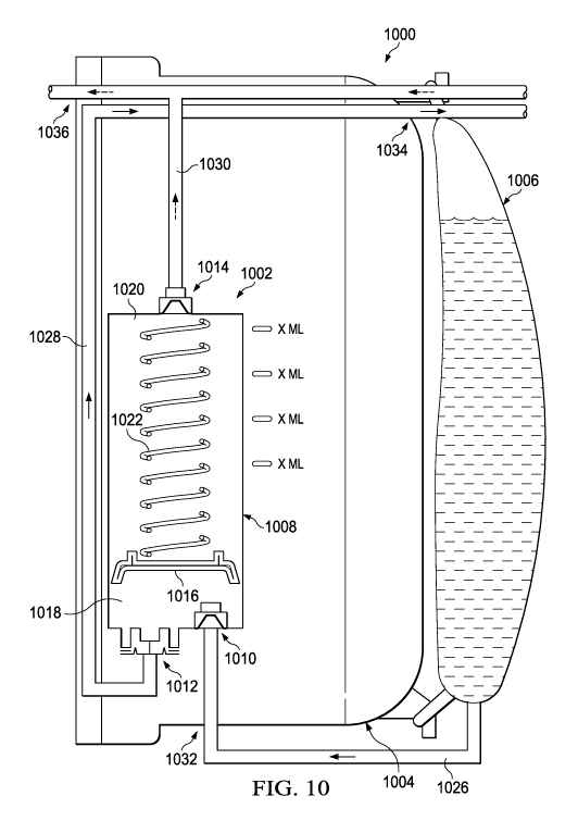
negative-
pressure intervals, and may instill a solution during venting intervals. For
example, during a
negative-pressure interval, negative pressure can be supplied by a negative-
pressure therapy
unit (not shown) and delivered by a tube 912 to the instillation regulator
600. In the
embodiment of Figures 9A-9C, negative pressure may be delivered to the second
chamber
904 through the solution outlet port 608, the passage 722, and the channel
723. Negative
pressure in the second chamber 904 can move the piston 702, expanding the
first chamber
902 and compressing the second chamber 904. If the first chamber 902 expands,
pressure in
the first chamber 902 can decrease proportionately. Negative pressure in the
first chamber
902 can have the effect of actively drawing instillation solution into the
first chamber 902
through the solution inlet port 606. The distance that the piston 702 travels
can determine a
CA 02965503 2017-04-21
WO 2016/065335 PCT/US2015/057240
dosage volume of instillation solution. The first chamber 902 may be lined
with a suitable
material to prevent contamination from mechanical components or lubricants.
For example,
the first chamber 902 may be lined with a film bag, an elastomeric bag, or a
compressible
bellows.
[0080] In some embodiments, the instillation dosage may be adjusted. Such
capability may be achieved by adjusting the distance traveled of the movable
components
during negative-pressure and venting intervals. For example, the spring 704
may be
compressed so that the distance traveled by the piston 702 can be limited.
This may result
from more quickly reaching the point where the negative pressure applied to
the second
chamber 904 for compressing the spring 704 can no longer overcome the force
exerted by the
spring 704. Other example embodiments may adjust the instillation dosage by
reducing the
height of the second chamber 904, for example, by screwing the first chamber
902 further
into the second chamber 904 using a threaded mechanism. Yet another example
may include
controlling the dosage of instillation fluid delivered by limiting the travel
of the piston 702
within the second chamber 904 by adjusting the height of a stop block located
within the
second chamber 904, under the piston 702. Additional examples may include
restricting the
flow of instillation fluid through either the solution inflow tube 920 or the
solution outflow
tube 912 using, for example, a valve, or by restricting the rate at which the
piston 702
recovers.
[0081] Expansion of the first chamber 902 may also have the effect of
decreasing
pressure in the third chamber 924, as pressure between the first chamber 902
and the third
chamber 924 may be equalized through the passage 926. The decreased pressure
in the third
chamber 924 may have the effect of closing the outlet check valve 710, which
can prevent
instillation of solution to a dressing during a negative-pressure interval.
[0082] During a venting interval, the vent 719 may provide fluid communication
between the second chamber 904 and the ambient environment, which can also
have the
effect of increasing pressure in the second chamber 904. Increased pressure in
the second
chamber 904 during a venting interval can have the effect of moving the piston
702,
compressing the first chamber 902 and expanding the second chamber 904. If the
first
chamber 902 is compressed, pressure in the first chamber 902 can increase
proportionately.
The resulting increase in pressure can move solution out of the first chamber
902 through the
valve seat 730, the channel 712, and the solution outlet port 608, instilling
solution to a tissue
site through the solution outflow tube 912. The inlet check valve 742 can
prevent back-flow
21
CA 02965503 2017-04-21
WO 2016/065335 PCT/US2015/057240
through the solution inlet port 606 during instillation, and the outlet check
valve 914 can
prevent solution from moving into the second chamber 904 from the channel 723
during
instillation. A flow limiter such as the hydrophobic filter 716 can control
the rate of venting
between the second chamber 904 and the ambient environment through the vent
719, which
can also determine the rate at which the piston 702 moves and the rate at
which solution can
be instilled from the first chamber 902. For example, the surface area of the
hydrophobic
filter 716 can determine the vent rate and can be calibrated to provide a
prescribed instillation
rate.
[0083] Figure 10 is a schematic diagram illustrating an example embodiment of
a
fluid management system 1000 comprising an instillation regulator 1002
disposed within an
exudate container 1004. The instillation regulator 1002 is an example
embodiment of the
instillation regulator 116 of Figure 1, and the exudate container 1004 may be
an example
embodiment of the container 112 of Figure 1. The fluid management system 1000
may also
include an ancillary instillation solution source, such as a solution bag
1006. The solution
bag 1006 may be an example embodiment of the solution source 114 of Figure 1.
In some
embodiments, the solution bag 1006 may be externally mounted on the exudate
container
1004, as illustrated in Figure 10. In other embodiments, the solution bag 1006
may be
secured to a pole or other hanger, preferably in close proximity to the
exudate container 1004.
[0084] The instillation regulator 1002 may be analogous in many respects to
the
instillation regulator 200 or the instillation regulator 600. For example, the
instillation
regulator 1002 may include a housing 1008, a solution inlet port 1010, a
solution outlet port
1012, and a negative-pressure port 1014. The instillation regulator 1002 may
also include a
piston 1016 disposed in a cavity of the housing 1008. The piston 1016 may
partition or
separate the cavity into a first chamber 1018 and a second chamber 1020.
Moreover, the
piston 1016 may engage the housing 1008 to provide a seal between the first
chamber 1018
and the second chamber 1020. A spring 1022 may be disposed between the piston
1016 and
the housing 1008, as illustrated in the example embodiment of Figure 10. The
piston 1016
may reciprocate within the housing 1008, varying the volume of the first
chamber 1018 and
the second chamber 1020.
[0085] As illustrated in Figure 10, the instillation regulator 1002 may be
disposed
within an interior space of the exudate container 1004 in some embodiments.
For example,
the instillation regulator 1002 may be fastened to a wall of the exudate
container 1004, or
may be integrally molded with the exudate container 1004. The instillation
regulator 1002
22
CA 02965503 2017-04-21
WO 2016/065335 PCT/US2015/057240
may also be fluidly coupled to the solution bag 1006, to a dressing (not shown
in Figure 10),
and to a negative-pressure source (not shown in Figure 10). For example, in
some
embodiments, the fluid management system 1000 may provide a fluid path 1026
between the
solution bag 1006 and the solution inlet port 1010, a fluid path 1028 between
the solution
outlet port 1012 and a dressing, and a fluid path 1030 between the negative-
pressure port
1014 and a negative-pressure source. The fluid path 1030 may additionally
couple the
negative-pressure source to the dressing through the exudate container 1004 in
some
embodiments.
[0086] Each of the fluid path 1026, the fluid path 1028, and the fluid path
1030 may
be comprised of more than one fluid conductor, coupled together through
suitable interfaces.
For example, in some embodiments, the fluid path 1026 may include an
integrated fluid
conductor molded into the exudate container 1004. In other embodiments, the
fluid path
1026 may include a tube. A fluid conductor can be coupled on a first end to
the solution inlet
port 1010 and terminate on a second end with an interface 1032 through the
exudate
container 1004. Another fluid conductor may be coupled between the interface
1032 and the
solution bag 1006. In other embodiments, the fluid path 1026 may be a tube,
which can be
coupled on a first end to the solution inlet port 1010, exit the exudate
container 1004 through
the interface 1032, and be coupled or configured to be coupled on a second end
to the
solution bag 1006. Similarly, in some embodiments, the fluid path 1028 may
include an
integral fluid conductor molded into the exudate container 1004. In other
embodiments, the
fluid path 1028 may include a tube. A fluid conductor can be coupled on a
first end to the
solution outlet port 1012 and terminate on a second end with an interface 1034
through the
exudate container 1004. Another tube or fluid conductor may be coupled between
the
interface 1034 and a dressing to complete a fluid path to the dressing. In
other embodiments,
the fluid path 1028 may be a tube, which can be coupled on a first end to the
solution outlet
port 1012, exit the exudate container 1004 through the interface 1034, and be
coupled or
configured to be coupled on a second end to a dressing. The fluid path 1030
may similarly
include an integrated fluid conductor or a tube coupled to a negative-pressure
source through
an interface 1036.
[0087] Figure 11 is a schematic diagram illustrating another example
embodiment of
a fluid management system 1100 comprising the instillation regulator 1002
disposed within
an exudate container 1104. The exudate container 1104 may be another example
embodiment of the container 112 of Figure 1. In some embodiments, the
instillation
23
CA 02965503 2017-04-21
WO 2016/065335 PCT/US2015/057240
regulator 1002 may be fastened to a wall of the exudate container 1104, or may
be integrally
molded with the exudate container 1104. The fluid management system 1100 may
also
include an instillation solution source, such as a syringe 1106. The syringe
1106 may be an
example embodiment of the solution source 114 of Figure 1. In some
embodiments, the
syringe 1106 may be externally mounted on the exudate container 1104, as
illustrated in
Figure 10. In other embodiments, the syringe 1106 may be secured to a pole or
other hanger,
preferably in close proximity to the exudate container 1104. The syringe 1106
can prime the
fluid management system 1100 with instillation fluid that can be obtained from
other sources,
such as from larger containers or from multiple containers. The syringe 1106
may also be
advantageous for accurately recording dosages of instillation solution
administered through
the fluid management system 1100.
[0088] Figure 12 is a schematic diagram illustrating another alternative
embodiment
of a fluid management system 1200. The fluid management system 1200 may
include the
instillation regulator 1002 integrated with an exudate container 1204. The
exudate container
1204 may be another example embodiment of the container 112 of Figure 1. In
some
embodiments, the instillation regulator 1002 may be fastened to a wall of the
exudate
container 1204, or may be integrally molded with the exudate container 1204.
The fluid
management system 1200 may also include an instillation solution source, such
as a solution
container 1206. The solution container 1206 may be another example embodiment
of the
solution source 114 of Figure 1. In some embodiments, the solution container
1206 may be
integrated with the exudate container 1204 to provide a single disposable
unit. For example,
in some embodiments, the solution container 1206 may be a pouch comprising a
suitable
plastic or liquid-impermeable film welded or otherwise secured to an external
surface of the
exudate container 1204. In other embodiments, the solution container 1206 may
be a rigid
plastic integrally molded with the exudate container 1204. The fluid path 1026
may also be
integrated in the exudate container 1204 in some embodiments to reduce
external tubes.
[0089] Figure 13 is a schematic diagram illustrating another alternative
embodiment
of a fluid management system 1300. The fluid management system 1300 may
include the
instillation regulator 1002 disposed within an exudate container 1304. The
exudate container
1304 may be an example embodiment of the container 112 of Figure 1. In some
embodiments, the instillation regulator 1002 may be fastened to a wall of the
exudate
container 1304, or may be integrally molded with the exudate container 1304.
The fluid
management system 1300 may also include an instillation solution source, such
as a solution
24
CA 02965503 2017-04-21
WO 2016/065335 PCT/US2015/057240
container 1306. The solution container 1306 may be an example embodiment of
the solution
source 114 of Figure 1. In some embodiments, the solution container 1306 may
be integrated
with the exudate container 1304 to provide a single disposable unit. For
example, in some
embodiments, the solution container 1306 may be a flexible pouch disposed
within an interior
space of the exudate container 1304. Disposing the solution container 1306
within the
exudate container 1304 may be advantageous for transport and storage, and may
also prevent
tampering and use of uncontrolled instillation solution. The volume displaced
by the solution
container 1306 can be reduced as instillation solution is delivered to a
tissue site, thereby
increasing the free volume in the exudate container 1304 available for
collecting exudate and
used instillation solution. A non-return valve can prevent the solution
container 1306 from
expanding under negative pressure in the exudate container 1304.
[0090] Figure 14 is a schematic diagram illustrating yet another example
embodiment
of a fluid management system 1400. The fluid management system 1400 may
include the
instillation regulator 1002 coupled externally to an exudate container 1404.
For example, in
some embodiments the instillation regulator 1002 may be disposed within,
integrated with, or
coupled to an adapter housing 1406, which can be coupled to the exudate
container 1404.
The exudate container 1404 and the adapter housing 1406 may each be configured
with
suitable interfaces to fluidly couple the solution inlet port 1010 to an
instillation solution
source (not shown in Figure 14), and to fluidly couple the solution outlet
port 1012 to a
dressing (not shown in Figure 14). The exudate container 1404 and the adapter
housing 1406
may also include suitable interfaces for fluidly coupling a negative-pressure
source (not
shown in Figure 14) to the negative-pressure port 1014 and to a dressing. In
some
embodiments, the instillation regulator 1002 or the adapter housing 1406 may
be detached
from the exudate container 1404 and re-used, particularly for a single
patient.
[0091] Figure 15 is a schematic diagram illustrating additional details that
may be
associated with some embodiments of a fluid management system 1500. The fluid
management system 1500 may be analogous to any of the previously described
embodiments
of a fluid management system, or any combination of features previously
described. For
example, the fluid management system 1500 may include the instillation
regulator 1002
disposed within an exudate container 1504. The exudate container 1504 may be
an example
embodiment of the container 112 of Figure 1. In some embodiments, the
instillation
regulator 1002 may be fastened to a wall of the exudate container 1504, or may
be integrally
molded with the exudate container 1504. The fluid management system 1500 may
optionally
CA 02965503 2017-04-21
WO 2016/065335 PCT/US2015/057240
include a means for controlling or adjusting a dosage of instillation
solution. For example, a
pin or adjustable lever 1506 may limit the range of motion of the piston 1016
in some
embodiments. In other example embodiments, the spring rate of the spring 1022
may be
increased or decreased.
[0092] Figure 16 is an assembly view illustrating an example embodiment of a
fluid
management system 1600. The fluid management system 1600 may include a
container
housing 1602, an instillation regulator 1604, a panel 1606, and a seal 1608.
The container
housing 1602 and the panel 1606 are preferably constructed from a material
that is
impermeable to fluid, such as a rigid or semi-rigid plastic. The seal 1608
preferably
comprises a material that is relatively pliable and impermeable to fluid. For
example, the seal
1608 may be manufactured from a non-porous polyester film, preferably having a
thickness
between 0.1 millimeters and 0.2 millimeters. The seal 1608 also preferably
comprises an
adhesive or other suitable means for attaching the seal 1608 to the panel
1606. For example,
the seal 1608 may include an acrylic adhesive applied to one side, preferably
having a
thickness of about 0.15 millimeters. In some embodiments, the seal 1608 may be
an adhesive
label or integrated with product labeling.
[0093] The fluid management system 1600 may also include tubes or other fluid
conductors for fluidly coupling the fluid management system 1600 to a tissue
site or other
components of a therapy system, such as the therapy system 100. For example,
as illustrated
in Figure 16, the fluid management system 1600 may include a tube 1610 for
coupling the
container housing 1602 to a tissue site, a tube 1612 for coupling the
container housing 1602
to an instillation solution source, and another tube 1614 for coupling the
container housing
1602 to a tissue site.
[0094] In some embodiments, the container housing 1602 may include fluid ports
adapted for coupling to tubes or other fluid conductors. For example, the
container housing
1602 may include a fluid port 1616 adapted for coupling to the tube 1610, a
fluid port 1618
adapted for coupling to the tube 1612, and a fluid port 1620 adapted for
coupling to the tube
1614.
[0095] In some embodiments, the instillation regulator 1604 may be similar or
analogous to the instillation regulator 1002 in many respects. For example,
the instillation
regulator 1604 may have fluid ports, such as a solution outlet port 1622 and a
solution inlet
port 1624, analogous to the solution outlet port 216 and the solution inlet
port 214,
respectively. The instillation regulator 1604 may also have retention clips
1626 adapted to
26
CA 02965503 2017-04-21
WO 2016/065335 PCT/US2015/057240
mechanically couple the instillation regulator 1604 to the panel 1606. A tube
or other fluid
conductor may also be coupled to the solution outlet port 1622 and the
solution inlet port
1624. For example, as illustrated in Figure 16, a tube 1628 may be coupled to
the solution
outlet port 1622 and a tube 1630 may be coupled to the solution inlet port
1624.
[0096] In some embodiments, the panel 1606 may also include fluid ports
adapted for
coupling to a tube or other fluid conductor. For example, as shown in Figure
16, the panel
1606 may include a port 1632, a port 1634, and a port 1636. A hydrophobic
filter 1638 may
also be coupled to or integral with some embodiments of the panel 1606.
[0097] Figure 17 is a rear view of the panel 1606 of Figure 16, illustrating
additional
details that may be associated with some embodiments. As illustrated in Figure
17, fluid
channels may be integrated into some embodiments of the panel 1606. For
example, the
panel 1606 of Figure 17 may include a channel 1702, a channel 1704, and a
channel 1706. In
some embodiments, each of the channel 1702, the channel 1704, and the channel
1706 may
be an open channel, as shown in Figure 17. Such an open channel may, for
example, be
formed as a groove, furrow, cut, depression, or gutter in the panel 1606. In
some
embodiments, an open channel may have a rectangular, semi-circular, or
trapezoidal cross-
section, for example. A passage through the panel 1606 may also be disposed at
each
terminus of the channels 1702-1706 in some embodiments. For example, a passage
1708
may be disposed at a first terminus of the channel 1702, and a passage 1710
may be disposed
at a second terminus of the channel 1702. Similarly, a passage 1712 may be
disposed at a
first terminus of the channel 1704 and a passage 1714 may be disposed at a
second terminus
of the channel 1704, and a passage 1716 and a passage 1718 may be disposed at
opposing
ends of the channel 1706. In the example embodiment of Figure 17, some or all
of the
passages 1708-1718 may be fluidly coupled to a fluid port on the opposing side
of the panel
1606. For example, the passage 1710 may be fluidly coupled to the port 1636,
the passage
1714 may be fluidly coupled to the port 1634, and the passage 1718 may be
fluidly coupled
to the port 1632. The panel 1606 may include additional passages, such as a
passage 1720,
which can fluidly couple a first side of the panel 1606 to a second side of
the panel 1606. In
some embodiments, the passage 1720 can be fluidly coupled to the hydrophobic
filter 1638.
[0098] The seal 1608 may be attached to the panel 1606 and cover the channels
1702-
1706 to form integrated fluid conductors. For example, the seal 1608 may cover
the channel
1702 to form an integrated fluid conductor between the passage 1708 and the
passage 1710.
The seal 1608 preferably covers and seals each of the channels 1702-1706, and
each of the
27
CA 02965503 2017-04-21
WO 2016/065335 PCT/US2015/057240
channels 1702-1706 is preferably deep enough to ensure that deformation of the
seal under
negative pressure does not cause the seal to block the channels 1702-1706.
[0099] Figure 18 is a perspective view of an example embodiment of the
assembled
fluid management system 1600. As illustrated in Figure 18, the tube 1610 may
be coupled to
the port 1616, the tube 1612 may be coupled to the port 1618, and the tube
1614 may be
coupled to the port 1620.
[00100] Figure 19 is a section view of the fluid management system
1600 taken
along line 19-19 of Figure 18, illustrating additional details that may be
associated with some
embodiments. As shown in the example embodiment of Figure 19, the panel 1606
is
preferably configured to be fastened to the container housing 1602 to enclose
the instillation
regulator 1604 and form an exudate container, which may be suitable for use
with some
embodiments of the fluid management systems previously described. In some
embodiments,
for example, the fluid management system 1600 may be assembled to provide
fluid paths
analogous to the fluid path 1026, the fluid path 1028, and the fluid path
1030.
[00101] For example, a fluid path analogous to the fluid path 1026
may be
provided by coupling a first end of the tube 1612 to the port 1618, and
coupling a second end
of the tube 1612 to an instillation solution source, such as the solution bag
1006, the syringe
1106, or the solution container 1206. The port 1618 may provide a fluid path
from the tube
1612 to the passage 1712, and the channel 1704 can provide a fluid path from
the passage
1712 to the passage 1714. The passage 1714 can provide a fluid path from the
channel 1704
to the port 1634. The tube 1630 can provide a fluid path between the port 1634
and the
solution inlet port 1624, thereby completing a fluid path between the
instillation solution
source and the solution inlet port 1624.
[00102] A fluid path analogous to the fluid path 1028 may also be
assembled
by coupling a first end of the tube 1614 to the port 1620, and coupling a
second end of the
tube 1614 to a dressing, such as the dressing 102. Assembled in this exemplary
configuration, the tube 1628 can provide a fluid path between the solution
outlet port 1622
and the port 1632. The port 1632 can provide a fluid path between the tube
1628 and the
passage 1718, which can be in fluid communication with the channel 1706. The
channel
1706 can provide a fluid path between the passage 1718 and the passage 1716,
which can be
in fluid communication with the port 1620, thereby completing a fluid path
between the
solution outlet port 1622 and the tube 1614.
28
CA 02965503 2017-04-21
WO 2016/065335 PCT/US2015/057240
[00103] In some embodiments, a fluid path analogous to the fluid
path 1030
may be provided by fluidly coupling the passage 1720 to a negative-pressure
source, such as
the negative-pressure source 104, for example. Assembled in this exemplary
configuration,
the passage 1720 can provide a fluid path between a negative-pressure source
and the interior
of the container housing 1602, preferably through the hydrophobic filter 1638.
The tube
1610 may be coupled to the port 1616, which can also be in fluid communication
with the
interior of the container housing 1602, thereby completing a fluid path
between a negative-
pressure source and the tube 1610. The tube 1610 can be fluidly coupled to a
dressing or
tissue site to extend the fluid path to the dressing or tissue site.
[00104] The tube 1610 preferably has at least two lumens, and the
port 1616
may also have two lumens in some embodiments. For example, in some
embodiments, a first
lumen of the tube 1610 may be fluidly coupled to a first lumen of the port
1616 to deliver
negative-pressure to a dressing or tissue site, and a second lumen of the tube
1610 may be
fluidly coupled to a second lumen of the port 1616 to provide a feedback path
for negative-
pressure from a dressing or tissue site. The first lumen of the port 1616 may
be in fluid
communication with the interior of the container housing 1602, and the second
lumen of the
port 1616 may be fluidly coupled to passage 1708 when assembled. In this
exemplary
configuration, the passage 1708 may provide a fluid path between the second
lumen of the
port 1616 and the channel 1702. The channel 1702 can provide a fluid path
between the
passage 1708 and the passage 1710, which can be in fluid communication with
the port 1636.
A tube or other fluid conductor, such as a tube 1902, may provide a fluid path
between the
port 1636 and a negative-pressure port 1904 of the instillation regulator
1604, thereby
completing a fluid path between the second lumen of the tube 1610 and the
negative-pressure
port 1904.
[00105] Figure 20 is an assembly view illustrating another example
embodiment of a fluid management system. The fluid management system 2000 of
Figure 20
may include a container housing 2002 and a panel 2004. The container housing
2002 and the
panel 2004 are preferably constructed from a material that is impermeable to
fluid, such as a
rigid or semi-rigid plastic.
[00106] The fluid management system 2000 also preferably includes an
instillation regulator. For example, in some embodiments, a regulator body
2006 may be
integrally molded with the panel 2004. In other embodiments, the regulator
body 2006 may
be inserted through an aperture in the panel 2004. In the example embodiment
of Figure 20,
29
CA 02965503 2017-04-21
WO 2016/065335 PCT/US2015/057240
the regulator body 2006 has a cylindrical wall 2008 and a base 2010, and
preferably has a
major axis that is orthogonal to the plane of the panel 2004 to simplify
molding.
[00107] Other regulator components, such as a spring 2012, a piston
2014, a
first check valve 2016, a second check valve 2018, and a head 2020, may be
assembled with
the regulator body 2006 to provide an instillation regulator that may be
analogous to the
instillation regulator 1002 in many respects. For example, the piston 2014 may
be disposed
in the regulator body 2006 and partition the regulator body 2006 into two
chambers,
analogous to the first chamber 1018 and the second chamber 1020. The spring
2012 may be
disposed between the piston 2014 and the base 2010, and the piston 2014 may
reciprocate
within the regulator body 2006. The head 2020 may be fastened to the regulator
body 2006
to enclose the spring 2012 and the piston 2014. The head 2020 may also include
a passage
2022 and a passage 2024. The base 2010 of the regulator body 2006 may include
an aperture
2026, analogous to the negative-pressure port 1014. A hydrophobic filter 2028
is preferably
disposed over the aperture 2026.
[00108] The fluid management system 2000 may also include tubes or
other
fluid conductors for fluidly coupling the fluid management system 2000 to a
tissue site or
other components of a therapy system, such as the therapy system 100. For
example, as
illustrated in Figure 20, the fluid management system 2000 may include a tube
2030 for
coupling the fluid management system 2000 to a tissue site, a tube 2032 for
coupling the fluid
management system 2000 to an instillation solution source, and another tube
2034 for
coupling the fluid management system 2000 to a dressing or tissue site.
[00109] Figure 21 is another assembly view illustrating additional
details that
may be associated with some embodiments of the fluid management system 2000.
As
illustrated in the example embodiment of Figure 21, the head 2020 may include
a solution
inlet port 2102 and a solution outlet port 2104, analogous to the solution
inlet port 1010 and
the solution outlet port 1012, respectively. The solution inlet port 2102 may
be fluidly
coupled to the passage 2022, and the solution outlet port 2104 may be fluidly
coupled to the
passage 2024. In some embodiments, the panel 2004 may also include additional
passages,
such as a passage 2106 and a passage 2108, as shown in the example embodiment
of Figure
21.
[00110] The panel 2004 is preferably configured to be fastened to
the container
housing 2002 to form an exudate container, which may be suitable for use with
some
embodiments of the fluid management systems previously described. In some
embodiments,
CA 02965503 2017-04-21
WO 2016/065335 PCT/US2015/057240
for example, the fluid management system 2000 may be assembled to provide
fluid paths
analogous to the fluid path 1026, the fluid path 1028, and the fluid path
1030.
[00111] For example, a fluid path analogous to the fluid path 1026
may be
provided by coupling a first end of the tube 2032 to the solution inlet port
2102, and coupling
a second end of the tube 2032 to an instillation solution source, such as the
solution bag 1006,
the syringe 1106, or the solution container 1206. The port 2102 may provide a
fluid path
from the tube 2032 to the passage 2022, which can be fluidly coupled to a
chamber formed
by the piston 2014 and the head 2020.
[00112] A fluid path analogous to the fluid path 1028 may also be
assembled
by coupling a first end of the tube 2034 to the solution outlet port 2104, and
coupling a
second end of the tube 2034 to a dressing, such as the dressing 102. The
passage 2024 can
provide a path between the solution outlet port 2104 and the chamber formed by
the piston
2014 and the head 2020.
[00113] In some embodiments, a fluid path analogous to the fluid
path 1030
may be provided by fluidly coupling the passage 2106 to a negative-pressure
source, such as
the negative-pressure source 104, for example. The passage 2106 may be in
fluid
communication with the interior of the container housing 2002, preferably
through a
hydrophobic filter. The aperture 2026 can also be in fluid communication with
the interior of
the container housing 2002. Thus, the interior of the container housing 2002
can provide a
fluid path between the passage 2106 and the aperture 2026. The hydrophobic
filter 2028
preferably provides a fluid path for negative-pressure between the aperture
2026 and the
interior of the container housing 2002, but substantially blocks the fluid
path for exudate and
other liquids.
[00114] The example systems, apparatuses, and methods described
herein may
provide significant advantages. For example, instillation solution can be
applied reliably
while reducing the size, complexity, and number of parts needed for effective
negative-
pressure therapy with instillation. Moreover, instillation therapy can be
provided even if
there is a fluid head height to overcome. Some embodiments can also eliminate
or reduce the
need for ancillary components, such as ancillary bags for instillation
solution, providing a
single disposable apparatus. Some embodiments can also use a single interface
pad and
tub eset.
[00115] While shown in a few illustrative embodiments, a person
having
ordinary skill in the art will recognize that the systems, apparatuses, and
methods described
31
CA 02965503 2017-04-21
WO 2016/065335 PCT/US2015/057240
herein are susceptible to various changes and modifications. Moreover,
descriptions of
various alternatives using terms such as "or" do not require mutual
exclusivity unless clearly
required by the context, and the indefinite articles "a" or "an" do not limit
the subject to a
single instance unless clearly required by the context.
[00116] The appended claims set forth novel and inventive aspects of
the
subject matter described above, but the claims may also encompass additional
subject matter
not specifically recited in detail. For example, certain features, elements,
or aspects may be
omitted from the claims if not necessary to distinguish the novel and
inventive features from
what is already known to a person having ordinary skill in the art. Features,
elements, and
aspects described herein may also be combined or replaced by alternative
features serving the
same, equivalent, or similar purpose without departing from the scope of the
invention
defined by the appended claims.
32