Note: Descriptions are shown in the official language in which they were submitted.
1
DESCRIPTION
TITLE: EXFOLIATIVE COATING FOR COMPRESSOR VANE OR BLADE
TECHNICAL FIELD
The disclosure herein relates to a vane or a blade of a
compressor for an aircraft jet engine or a gas turbine engine,
and in particular relates to a compressor vane or blade capable
of keeping good aerodynamic properties as deposits on surfaces
of the vane or the blade naturally exfoliate.
BACKGROUND ART
In an aircraft jet engine or a gas turbine engine, its
combustor creates high-speed hot gas, its turbine extracts
energy from the hot gas, and part of the energy is used to
drive its compressor. The compressor sucks ambient air and
compresses and supplies it to the combustor. The air is, in
the compressor, adiabatically compressed and therefore
generates high temperatures about 400 - 700 degrees C for
example.
While the ambient air contains various types of dust and
sand as well as volcanic ash in some cases, it is unavoidable
that these substances flow into the compressor. Part of these
substances may, along with the compressed air, pass through
the compressor and be exhausted out but another part thereof
may adhere to the vanes and the blades of the compressor. The
CA 2965607 2019-05-10
CA 02965607 2017-04-24
2
ambient air further contains moisture, sulfates, sulfites,
chlorides, carbonates and such in the form of gas or minute
droplets, which may adhere to the vanes and the blades of the
compressor as well. These foreign substances are, by being
exposed to high temperatures, physically and chemically
changeable into deposits that adhere to the surfaces of the
vanes and the blades.
Because an excessive amount of deposits impairs the
aerodynamic properties of the compressor vanes and blades, it
is necessary to remove them, and, if necessary, re-finish
surfaces of the vanes and the blades, in order to restore these
original states.
Required work includes processes of
disassembling the engine, taking out each compressor vane or
blade, restoring these original states individually, and re-
assembling them into the engine. These laborious processes
cause a marked rise in cost about overhauling the engine.
There are some proposals about some arts for coatings to
address the problem raised by the deposits. The
Patent
Literatures 1 and 2 disclose related arts. Coatings disclosed
therein are intended to prevent adhesion of foreign substances.
Citation List
Patent Literature
PTL 1: United States Patent Application Publication
2010/0247321
PTL 2: United States Patent Application Publication
2010/0086397
3
SUMMARY
TECHNICAL PROBLEM
Coatings according to the aforementioned related arts
may work in the early stage where the foreign substances start
to adhere to the surfaces of the vanes and blades to prevent
adhesion thereof. Once the adhesion starts and sticking
deposits start to form, however, the coated surfaces are
covered by the deposits and subsequently arriving foreign
substances can become deposited on the precedent deposits. It
could not be expected in this stage that the effect of the
coatings amounts to much and therefore the deposits would grow
as much as those in the prior arts do. More specifically, what
these related arts do is nothing more than retardation of the
early stage of deposition and therefore these arts cannot
essentially solve the problem of the deposits. The contents
disclosed in the specification are arts created in order to
solve these problems originated from environments containing
abundant foreign substances.
SOLUTION TO PROBLEM
A compressor vane or blade for an engine used in an
environment containing abundant foreign substances is
comprised of a base body of the compressor vane or blade; and
a coating covering the base body, the coating consisting of a
nitride of titanium beyond 60 at% but less than 85 at% and a
balance of silicon.
CA 2965607 2018-04-27
4
ADVANTAGEOUS EFFECTS
Oxides generated at the interface between the coating
and the deposits promote exfoliation of the deposits, thereby
keeping preventing deposition of the deposits for a long term.
BRIEF DESCRIPTION OF DRAWINGS
FIG. I is a schematic cross sectional view of a base body
and a coating in accordance with an embodiment.
FIG. 2 is a schematic cross sectional view of a base body
and a coating in accordance with another embodiment.
FIG. aA is a schematic cross sectional view showing a
state where foreign substances adhere to the coating to form
deposits.
FIG. 3B is a schematic cross sectional view showing a
state where the coating reacts with sulfates contained in the
foreign substances to create an exfoliative layer.
FIG. 3C is a schematic cross sectional view showing a
state where the exfoliative layer along with the deposits comes
off from the coating.
FIG. 4 is a schematic drawing of a burner rig test
apparatus.
CA 2965607 2018-04-27
CA 02965607 2017-04-24
DESCRIPTION OF EMBODIMENTS
Exemplary embodiments will be described hereinafter with
reference to the appended drawings.
As described already, the foreign substances sucked into
5 the engine contain sulfates. Sulfates are more oxidative than
oxygen and therefore gradually corrode even highly corrosion-
resistant materials such as CrAlN when combined with a high
temperature environment. While
such corrosion results in
formation of metal oxides, numerous metal oxides generated in
such an environment have compact structures and are rigid, and
in some cases function as anchors for holding the deposits.
Therefore they do not prevent, but rather sometimes promote,
adhesion of subsequent deposits thereon.
The present inventors discovered that specific metals
can form coarse and brittle oxides even in the environment at
issue. Examples thereof could be titanium, or zirconium and
hafnium as its equivalents in chemical properties, and vanadium,
or niobium and tantalum as its equivalents in chemical
properties.
The present inventors further discovered that these
oxides come into being at an interface between the deposits
and the coating and have a property of promoting exfoliation
of them (sometimes referred to as "exfoliative property"
hereinafter). The deposits would thereby get exfoliated before
growing up into a thick layer and be blown off by flow of the
compressed air. The coating could repeatedly recover its fresh
CA 02965607 2017-04-24
6
surface and therefore the property of promoting exfoliation of
the deposits could be maintained for a long term. This
property is available to compressor vanes and blades of an
aircraft jet engine or a gas turbine engine for suppressing
deposition of deposits for a long term.
Creation of the contents disclosed herein has been
achieved on the basis of these discoveries.
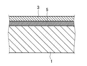
Referring to FIG. 1, an engine compressor vane or blade
according to an embodiment is comprised of a base body 1 of
the compressor vane or blade and a coating 3 covering the base
body 1. The
base body 1 is one of vanes and blades of a
compressor for an aircraft jet engine or a gas turbine engine
and is applicable to either a rotor blade or a stator vane.
The coating 3 is of a titanium-silicon nitride (TixSii,N) for
example. The coating thickness may be arbitrarily determined
but may be 3 micrometers or more for example as a greater
thickness is advantageous in order to ensure a longer lifetime.
Further, it may be 10 micrometers or less for example as a
smaller thickness is advantageous in order to reduce a risk
for causing defects.
Titanium and silicon contained in the coating 3, when
coexisting with sulfates, form complex oxides at considerably
elevated temperatures. Complex oxides containing titanium, as
having an action of promoting exfoliation of deposits from the
coating 3 as described already, suppresses deposition of the
deposits for a long term. Throughout the present description
7
a coating having such a property is referred to as "exfoliative
coating".
The ratio of titanium to silicon in the nitride may be
arbitrarily selected. However, when titanium is 0 at% (x = 0),
the aforementioned effect could not be enjoyed. Therefore
titanium should be beyond 0 at and preferably be 60 at% or
more. On the
other hand, as compared with the case where
titanium is 100 at% (x = 1), some properties such as corrosion-
resistance could be improved when silicon is contained therein.
Therefore titanium is less than 100 at% and is more preferably
80 at% or less. Silicon is preferably 15 at% or more and is
also preferably 40 at% or less.
Titanium could be substituted for zirconium or hafnium,
both of which have equivalent chemical properties as described
above. More
specifically, the coating 3 may include a
zirconium-silicon nitride (ZrSii,N) or a hafnium-silicon
nitride (HfxSii,N).
Vanadium, or chemical equivalents such as niobium or
tantalum, is available as the exfoliative coating as described
earlier. More
specifically, the coating 3 may be of any
nitrides of one or more metals selected from the group of
vanadium, niobium and tantalum.
A smoother surface of the coating 3 is advantageous in
light of prevention of adhesion of the deposits. Thus the
surface roughness of the coating 3 is preferably 0.1 Ra or less
(Ra is an arithmetic average roughness based on Japanese
CA 2965607 2018-04-27
CA 02965607 2017-04-24
8
Industrial Standards: JIS-B-0601-2001).
Mere exposure of the aforementioned coating 3 is enough
for exhibiting the inherent property and therefore, below the
coating 3, any intermediate coating 5 distinguishable therefrom
may be interposed. The intermediate coating 5 is formed of,
or includes, any components distinct from the coating 3, or
alternatively may be formed of the same components but have a
distinct composition. The intermediate coating 5 may further
include two or more layers that are distinguishable from each
other.
The components for the intermediate coating 5 may be
arbitrarily selected in light of various properties. A
titanium-aluminum nitride (TiyAl1_0\1) or a chromium-aluminum
nitride (Cr,Allõlq) is applicable to the coating 5 in light of
improvement of corrosion-resistance and erosion-resistance for
example. Alternatively, any substances that are advantageous
for improving adhesion between the coating 3 and the base body
1 or relaxing stress around the interface can be selected and
applied to the coating 5.
Still alternatively, the coating 3 and another coating 7
may be alternately layered to form a multi-layered coating of
three or more sets of the alternate layers as shown in FIG. 2.
To form a multi-layered structure is advantageous for relaxing
residual stress or such.
In the multi-layered coating, for example, a coating of
a titanium-silicon nitride and a coating of a titanium-aluminum
CA 02965607 2017-04-24
9
nitride may be alternately layered. Alternatively, a coating
of a titanium-silicon nitride and a coating of a vanadium
nitride may be alternately layered. Still alternatively, both
of them may be titanium-silicon nitrides but ratios of titanium
to silicon therein may be differentiated. The other coating 7
by itself may include two or more layers mutually
distinguishable. Further, in the multi-layered coating, the
uppermost layer is preferably the coating 3. In the multi-
layered coating, each layer may be about from 10 to 20 nm in
thickness.
While the coating 3 fully covers the airfoil faces of
the engine compressor vane or blade at least, it may further
cover its platform section (in a case of a rotor blade), or
its inner band section and its outer band section (in a case
of a stator vane). Further the coating 3 may be limited to
these sections. Other sections in the engine compressor vane
or blade are either a section used for fixation to the engine
or a section to rub against another member. These sections
will, if coated by any hard coating such as nitrides, will soon
wear the opposite member off. To limit the coating on the
airfoil faces and the platform section or the inner band
section and the outer band section is advantageous for
elongating the lifetime of the opposite member.
Mechanisms by which the coating 3 prevents deposition of
the deposits will be described with reference to FIGs. 3A
through 30.
CA 02965607 2017-04-24
Deposits 9 contain dust, sand, volcanic ash, moisture,
sulfates, sulfites, chlorides, carbonates and such, and can
adhere onto the coating 3 as shown in FIG. 3A. The combination
of oxidative power by the sulfates or such and elevated
5 temperatures about 400 - 700 degrees C for example created by
adiabatic compression of the air causes formation of oxides 11
of the coating 3 at the interface between the coating 3 and
the deposits 9 as shown in FIG. 3E.
As these oxides 11 contain brittle substances such as
10 titanium oxide or such, the deposits 9 along with the oxides
11 exfoliate therefrom. Observation of its cross section by
TEM or such shows that only a layer of the oxides 11 several
hundred nm in thickness at the most exists there. More
specifically, it is considered that the oxides 11 would
exfoliate before it grows up to several hundred nm in thickness.
After the exfoliation, a fresh surface of the coating 3
is exposed as shown in FIG. 30, and can create again the action
of promoting exfoliation of deposits that are going to adhere
onto the surface. Loss of the coating 3 in each occasion of
exfoliation would be no more than several hundred nm in
thickness as the layer of the oxides 11 could exfoliate before
growing thick as described above. In
contrast, as the
thickness of the coating 3 is about 3 - 10 micrometers as also
described above, the coating 3 survives even after repeating
exfoliation several ten times and therefore keeps its effects
for a long term.
CA 02965607 2017-04-24
11
The coating 3 (or the coatings 5, 7 as well) on the base
body 1 can be formed by using a known arc ion plating method
for example.
Alternatively, a sputtering method or any of
other coating methods is also applicable. The
production
method will be described below, in which the arc ion plating
method is applied.
First the base body 1 and a raw material for evaporation
are introduced into an arc ion plating apparatus. In a case
where the coating 3 is to be formed of a titanium-silicon
nitride, the raw material is an ingot of a titanium-silicon
alloy. Its composition should be selected in accordance with
a target composition as desired in the coating.
In a case where the base body 1 is a rotor blade, its
dovetail section is fit into the holder to combine the base
body with the holder. This is not only to establish electrical
connection but also uses the holder to shelter the dovetail
section from discharge, thereby being helpful to limit
formation of the coating to a restricted portion. More
specifically, this is helpful to limit formation of the coating
to the airfoil faces and the platform section of the rotor
blade. In a
case where the base body 1 is a stator vane,
structures outside the outer band section or inside the inner
band section are used. This is helpful to limit formation of
the coating to the airfoil faces and the outer band section or
the inner band section of the stator vane.
The chamber is gas-tightly closed and evacuated down to
CA 02965607 2017-04-24
12
a proper vacuum by means of a vacuum pump. This is helpful to
eliminate impurities. The
evacuation is continued to the
extent that a degree of vacuum reaches about 0.01 Pa or such.
With continued evacuation, valves of the gas supplier
device are opened and thereby argon and nitrogen are introduced
therein so as to regulate the pressure in the chamber. The
pressure is 2 - 10 Pa for example.
By a discharge power source, a voltage is applied between
the evaporation source and the chamber to generate discharge
therebetween, and, simultaneously by a bias power source, a
bias voltage is applied to the base body 1. The titanium-
silicon alloy as the evaporation source works as a cathode to
generate the discharge. And as
well, titanium and silicon
change into vapor and are partly ionized and accelerated by
the bias voltage toward the base body 1. They
react with
nitrogen in the gas phase to form the coating 3.
As described already, sections sheltered in the holder
are free from formation of the coating but gas phase particles
are induced by the bias electric field to come around to all
the exposed surfaces of the base body 1. Thereby the coating
3 fully covers all the surfaces other than the sheltered
surfaces.
For the purpose of verifying the effects, burner rig
tests are executed to compare adhesion amounts of deposits.
Referring to FIG. 4, a burner rig test apparatus is
generally constituted of a burner 13 for generating hot gas
CA 02965607 2017-04-24
13
and a holder 15 for supporting test pieces. To the burner 13,
a fuel nozzle 17 comprised of a supply system for supplying
kerosene for example and a salt water nozzle 19 comprised of a
salt water supply system are connected. As gas flow expelled
from these nozzles is ignited by a plug 21, hot gas flow F is
generated. The holder 15 is so constituted as to support a
plurality of test pieces P of a round bar shape. By rotating
the holder 15 around an axis perpendicular to the gas flow F
by means of a motor 23, the plurality of test pieces P is
unitarily exposed to the hot gas flow F.
Test pieces of a round bar shape formed of INCONEL718
(INCONEL is a name commonly used by persons skilled in this
art field) on which titanium-silicon nitride (TiSiN) coatings
are formed, test pieces on which vanadium nitride (VN) coatings
are formed, and test pieces without coatings are respectively
produced.
Table 1 summarizes relations between the compositions of
the evaporation raw materials (target compositions) and the
compositions in the formed coatings, in regard to the titanium-
silicon nitride. In this
table, the compositions of the
coatings are results from elemental analyses by EPMA, each in
which three spots in each SEM image are subject to point
analysis and results are averaged.
14
Table 1 Compositions of Coatings (at%)
Evaporated Material
Composition of Coating (at%)
(Target Composition)
Ti: Si Ti Si
85:15 87.8 12.2
75:25 78.5 21.5
60:40 61.9 38.1
As being apparent from Table 1, slight shifts from the
compositions of the evaporation raw materials could be
respectively acknowledged. It is, nevertheless, apparent that
the compositions of the coatings can be regulated in accordance
with the compositions of the evaporation raw materials. In
the following description, the compositions of the coatings
are not based on results of elemental analyses but on the
compositions of the evaporation raw materials (target
compositions). The coatings will often be expressed in the
form such as Tio.75Sio.2511- so that the coatings are expressed in
combination with these compositions.
The aforementioned test pieces are respectively served
for the burner rig test. As salt water, calcium sulfate
solution is supplied to the burner. Each test piece is
attached to the holder and is, with rotating the holder,
exposed to hot gas flow for two hours, thereafter detached
therefrom and subject to visual observation and weight change
measurement. Thereafter each test piece is again attached to
the holder and is, with rotating the holder, exposed to hot
gas flow for forty hours, thereafter detached therefrom and
subject to visual observation and weight change measurement.
CA 2965607 2018-04-27
CA 02965607 2017-04-24
Table 2 summarizes the measurement results of weight changes.
Table 2 Weight Changes after Burner Rig Tests
Coating First Exposure (2 hours) Second Exposure (40
hours)
Tia75S10l5N 0.10 alo
vN 0.03 0.08
no coating 038 031
The test pieces without the coatings exhibit ash gray
deposits adhering on whole portions exposed to the hot gas
5 flow. While the test pieces with the coatings also exhibit
ash gray deposits, these deposits are partly exfoliated and
portions from which the deposits come off exhibit metallic
luster. The results of the weight change measurements present
that the test pieces without the coatings make considerable
10 weight gains, which are considered to be corresponding to the
weights of the deposits, but the test pieces with the coatings
only make slight weight gains. As being apparent from these
test results, the test pieces with the coatings have a
prominent effect of promoting exfoliation of the deposits as
15 compared with those without the coatings.
Influence of the compositions in the titanium-silicon
nitride coatings is studied. Test pieces with a Tio.85Sio.15N
coating, a Tio.75Sio.25N coating and a TioAoSioAoN coating,
respectively, are produced by changing the compositions in the
evaporating raw materials in a process similar to the
aforementioned process, and are served for the burner rig test.
Table 3 summarizes the measurement results of weight changes.
Meanwhile, it is noted that the present test cannot be compared
with the aforementioned test because the present test had been
CA 02965607 2017-04-24
16
executed in an opportunity distinct from the aforementioned
test, and therefore comparison is only possible within the
present test.
Table 3 Influence of Composition on Weight Change
Coating First Exposure (2 hours) Second Exposure (40
hours)
Tio.85Sio.15N 0.17 0.19
Tio75Sio25N 0/3 035
TiaNSio.oN 0/3 0.41
As being apparent from these measurement results of
weight changes, in the range of 60 at% or more and 85 at% or
less of titanium relative to the total of titanium-silicon,
the effect of promoting exfoliation of the deposits can be
acknowledged as with the case of 75 at%. In this range, however,
greater ratios of titanium seem to be more effective.
Comparison between single layer coatings and multi-
layered coatings is executed. Table 4 summarizes the
measurement results of weight changes. It is noted again that
the present test cannot be compared with the aforementioned
tests because the present test had been executed in an
opportunity distinct from the aforementioned tests. In the
multi-layered coatings, titanium-silicon nitride layers are
alternated with the other layers into three sets. Each layer
is about 20 nm in thickness.
CA 02965607 2017-04-24
17
Table 4 Comparison between Single Layered Coating and Multi-Layered Coating
Coating First Exposure (2 hours) Second Exposure (40
hours)
Tio.85Sio.15N
0.17 0.19
Single Layer
Tio.75Sio.25N
0.23 0.35
Single Layer
Tio.6oSio.4oN
0.23 0.41
Single Layer
Tio.75S10.25N / VN
0.12 0.14
Multi-Layer
Tio.75Sio.25N / TiN
0.24 0.41
Multi-Layer
Tio.75Sio.25N / CrN
0/3 043
Multi-Layer
From the measurement results of weight changes, it is
apparent that the multi-layered coatings exhibit similar
effects. Particularly the multi-layered coating of the
combination of titanium-silicon nitride and vanadium nitride
is excellent in the effects.
Although certain embodiments have been described above,
modifications and variations of the embodiments described above
will occur to those skilled in the art, in light of the above
teachings.
INDUSTRIAL APPLICABILITY
An engine compressor vane or blade is provided, on which
deposits hardly deposit even in an environment containing
abundant foreign substances.