Note: Descriptions are shown in the official language in which they were submitted.
NEAR-BIT GAMMA RAY SENSORS IN A ROTATING SECTION
OF A ROTARY STEERABLE SYSTEM
FIELD OF THE INVENTION
The present disclosure relates generally to well drilling operations and, more
particularly, to near-bit gamma ray sensors in a rotating section of a rotary
steerable system.
BACKGROUND
Hydrocarbons, such as oil and gas, are commonly obtained from subterranean
formations that may be located onshore or offshore. The development of
subterranean
operations and the processes involved in removing hydrocarbons from a
subterranean formation
are complex. Typically, subterranean operations involve a number of different
steps such as, for
example, drilling a wellbore at a desired well site, treating the wellbore to
optimize production of
hydrocarbons, and performing the necessary steps to produce and process the
hydrocarbons from
the subterranean formation.
Drilling a wellbore may include introducing a drill bit into formation and
rotating
the drill bit with a drill string. In certain operations, a rotary steerable
system (RSS) may be and
used to precisely locate the drill bit--both vertically and horizontally--in
the formation by altering
an axis of the drill bit with respect to the wellbore. A point-the-bit system
generally refers to an
RSS in which an axis of the drill bit is altered with respect to the axis of
the RSS. A push-the-bit
system generally refers to an RSS in which hydraulic or other fluid-controlled
pistons extend
from the RSS and contact the wall of the borehole.
Drilling a wellbore may also include collecting of measurements of the
subterranean formation that may guide the drilling operation. Example
measurements include,
but are not limited to, resistivity, gamma ray, sonic, nuclear magnetic
resonance, and seismic
measurements. For steering applications, collecting measurements at or near
the drill bit may
facilitate quicker and more accurate drilling decisions. Generating
measurements at or near the
drill bit may be problematic, however, depending on the configuration of the
RSS, which may be
coupled to or located directly above the drill bit.
SUMMARY OF THE INVENTION
A rotary steerable system for positioning within a subterranean formation
includes an outer housing and a drive shaft at least partially within and
rotationally independent
from the outer housing. A drill bit may be coupled to the drive shaft. At
least one gamma ray
sensor may be rotationally coupled to the drive shaft within the outer
housing. The at least one
gamma ray sensor senses gamma rays emitted by a formation in one or more
angular orientations
1
CA 2965630 2018-09-13
with respect to the drive shaft. In certain embodiments, the rotary steerable
system further
includes a housing rotationally coupled to the drive shaft, wherein the
housing comprises at least
one pressurized cavity; and the at least one gamma ray sensor is located
within the at least one
pressurized cavity. Measurements of the subterranean formation taken by the
gamma ray sensors
may be used to determine characteristics of the subterranean formation in
order to guide drilling
operations.
FIGURES
Some specific exemplary embodiments of the disclosure may be understood by
referring, in part, to the following description and the accompanying
drawings.
Figure 1 is a diagram illustrating an example drilling system, according to
aspects
of the present disclosure.
Figure 2 is a diagram of a portion of an example RSS, according to aspects of
the
present disclosure.
Figure 3 is a diagram of example gamma ray sensors within a housing, according
to aspects of the present disclosure.
Figure 4 is a diagram of an example housing comprising an inner sleeve and an
outer sleeve, according to aspects of the present disclosure.
Figure 5 is a diagram of another example housing comprising an inner sleeve
and
an outer sleeve, according to aspects of the present disclosure.
Figure 6 is a diagram of another example housing comprising an inner sleeve
and
an outer sleeve, according to aspects of the present disclosure.
While embodiments of this disclosure have been depicted and described and are
defined by reference to exemplary embodiments of the disclosure, such
references do not imply a
limitation on the disclosure, and no such limitation is to be inferred. The
subject matter
disclosed is capable of considerable modification, alteration, and equivalents
in form and
function, as will occur to those skilled in the pertinent art and having the
benefit of this
disclosure. The disclosed embodiments are provided by way of example only, and
are not
exhaustive of the scope of the disclosure.
2
CA 2965630 2018-09-13
CA 02965630 2017-04-24
k WO 2016/105406 PCT/US2014/072325
DETAILED DESCRIPTION
The present disclosure relates generally to well drilling operations and, more
particularly, to near-bit gamma ray sensors in a rotating section of a rotary
steerable system.
In the interest of clarity, not all features of an actual implementation may
be
described in this specification. It will of course be appreciated that in the
development of any
such actual embodiment, numerous implementation-specific decisions are made to
achieve the
specific implementation goals, which will vary from one implementation to
another. Moreover,
it will be appreciated that such a development effort might be complex and
time-consuming, but
would, nevertheless, be a routine undertaking for those of ordinary skill in
the art having the
benefit of the present disclosure.
To facilitate a better understanding of the present disclosure, the following
examples of certain embodiments are given. In no way should the following
examples be read to
limit, or define, the scope of the invention. Embodiments of the present
disclosure may be
applicable to horizontal, vertical, deviated, or otherwise nonlinear wellbores
in any type of
subterranean formation. Embodiments may be applicable to injection wells as
well as
production wells, including hydrocarbon wells. Embodiments may be implemented
using a tool
that is made suitable for testing, retrieval and sampling along sections of
the formation.
Embodiments may be implemented with tools that, for example, may be conveyed
through a
flow passage in tubular string or using a wireline, slickline, coiled tubing,
downhole robot or the
like.
Certain systems and methods are discussed below in the context of petroleum
drilling and production operations in which information is acquired relating
to parameters and
conditions downhole. Several methods exist for downhole information
collection, including
logging-while-drilling ("LWD") and measurement-while-drilling ("MWD"). In LWD,
data is
typically collected during the drilling process, thereby avoiding any need to
remove the drilling
assembly to insert a wireline logging tool. LWD consequently allows the
driller to make accurate
real-time modifications or corrections to optimize performance while
minimizing down time.
MWD is the term for measuring conditions downhole concerning the movement and
location of
the drilling assembly while the drilling continues. LWD concentrates more on
formation
parameter measurement. While distinctions between MWD and LWD may exist, the
terms
MWD and LWD often are used interchangeably. For the purposes of this
disclosure, the term
LWD will be used with the understanding that this term encompasses both the
collection of
formation parameters and the collection of information relating to the
movement and position of
3
CA 02965630 2017-04-24
WO 2016/105406 PCT/US2014/072325
the drilling assembly.
For purposes of this disclosure, an information handling system may include
any
instrumentality or aggregate of instrumentalities operable to compute,
classify, process, transmit,
receive, retrieve, originate, switch, store, display, manifest, detect,
record, reproduce, handle, or
utilize any form of information, intelligence, or data for business,
scientific, control, or other
purposes. For example, an information handling system may be a personal
computer, a network
storage device, or any other suitable device and may vary in size, shape,
performance,
functionality, and price. The information handling system may include random
access
memory (RAM), one or more processing resources such as a central processing
unit (CPU) or
hardware or software control logic, ROM, and/or other types of nonvolatile
memory. Additional
components of the information handling system may include one or more disk
drives, one or
more network ports for communication with external devices as well as various
input and
output (I/O) devices, such as a keyboard, a mouse, and a video display. The
information handling
system may also include one or more buses operable to transmit communications
between the
various hardware components. It may also include one or more interface units
capable of
transmitting one or more signals to a controller, actuator, or like device.
For the purposes of this disclosure, computer-readable media may include any
instrumentality or aggregation of instrumentalities that may retain data
and/or instructions for a
period of time. Computer-readable media may include, for example, without
limitation, storage
media such as a direct access storage device (e.g., a hard disk drive or
floppy disk drive), a
sequential access storage device (e.g., a tape disk drive), compact disk, CD-
ROM, DVD, RAM,
ROM, electrically erasable programmable read-only memory (EEPROM), and/or
flash memory;
as well as communications media such wires, optical fibers, microwaves, radio
waves, and other
electromagnetic and/or optical carriers; and/or any combination of the
foregoing.
The terms "couple" or "couples" as used herein may involve either a direct or
indirect connection. For example, two mechanically coupled devices may be
directly
mechanically coupled when the mechanical coupling involves close or direct
physical contact
between the two devices, or indirectly mechanically coupled when the two
devices are each
coupled to an intermediate component or structure. The term "communicatively
coupled" as
used herein generally refers to an electronic (or, in some cases, fluid)
connection via which two
elements may electronically (or fluidically) communicate. An electronic
coupling typically
enables electrical power and/or data flow between elements. Such an electronic
connection may
involve a wired and/or wireless connection, for example, using Wifi,
Bluetooth, or other wireless
4
CA 02965630 2017-04-24
WO 2016/105406 PCT/US2014/072325
protocol, LAN, co-axial wiring, fiber-optic wiring, hard-wired physical
connections, circuit
board traces, or any other electronic signal medium or combinations thereof.
As with direct and
indirect physical connections, a first device may be directly communicatively
coupled to a
second device, such as through a direct electronic connection, or indirectly
communicatively
coupled, via intermediate devices and/or connections.
Figure 1 is a diagram of a subterranean drilling system 100 including an
example
RSS 124, according to aspects of the present disclosure. The drilling system
100 comprises a
drilling platform 102 positioned at the surface 104. In the embodiment shown,
the surface 104
comprises the top of a formation 106 containing one or more rock strata or
layers 106a-d, and the
drilling platform 102 may be in contact with the surface 104. In other
embodiments, such as in
an off-shore drilling operation, the surface 104 may be separated from the
drilling platform 102
by a volume of water.
The drilling system 100 comprises a derrick 108 supported by the drilling
platform 102 and having a traveling block 138 for raising and lowering a drill
string 114. A
kelly 136 may support the drill string 114 as it is lowered through a rotary
table 142 into a
borehole 110. A pump 130 may circulate drilling fluid through a feed pipe 134
to kelly 136,
downhole through the interior of drill string 114, through orifices in a drill
bit 118, back to the
surface via an annulus 140 formed by the drill string 114 and the wall of the
borehole 110. Once
at the surface, the drilling fluid may exit the annulus 140 through a pipe 144
and into a retention
pit 132. The drilling fluid transports cuttings from the borehole 110 into the
pit 132 and aids in
maintaining integrity or the borehole 110.
The drilling system 100 may comprise a bottom hole assembly (BHA) 116
coupled to the drill string 114 near the drill bit 118. The BHA 116 may
comprise a LWD/MWD
tool 122 and a telemetry element 120. The LWD/MWD tool 122 may include
receivers and/or
transmitters (e.g., antennas capable of receiving and/or transmitting one or
more electromagnetic
signals). As the borehole 110 is extended by drilling through the formations
106, the
LWD/MWD tool 122 may collect measurements relating to various formation
properties as well
as the tool orientation and position and various other drilling conditions.
The telemetry sub 120 may transfer measurements from the BHA 116 to a surface
receiver 146 and/or receive commands from the surface receiver 146. The
measurements may
comprise measurements from the LWD/MWD tool 122 and/or from the RSS 124, as
will be
described below. The telemetry sub 120 may transmit measurements or data
through one or
more wired or wireless communications channels (e.g., wired pipe or
electromagnetic
5
CA 02965630 2017-04-24
WO 2016/105406 PCT/US2014/072325
propagation). Alternatively, the telemetry sub 120 may transmit data as a
series of pressure
pulses or modulations within a flow of drilling fluid (e.g., mud-pulse or mud-
siren telemetry), or
as a series of acoustic pulses that propagate to the surface through a medium,
such as the drill
string 114. Commands received at the telemetry sub 120 may be transmitted to
the elements of
the BHA 116 to which the commands are directed.
In certain embodiments, the drilling system 100 may comprise an information
handling system 148 positioned at the surface 104. The information handling
system 148 may be
communicably coupled to the surface receiver 146 and may receive measurements
from the
BHA 116 and/or transmit commands to BHA 116 though the surface receiver 146.
The
information handling system 148 may also receive measurements from the
elements of the BHA
116 when they are retrieved at the surface 102. In certain embodiments, the
information
handling system 148 may process the measurements to determine certain
characteristics of the
formation 106, and may transmit commands one or more elements of the BHA 116
that are
based, at least in part on the determined formation characteristics.
The drill bit 118 may be driven by a downhole motor (not shown) and/or
rotation
of the chill string 114 to drill the borehole 110 in the formation 106. In
certain embodiments, the
downhole motor (not shown) may be incorporated into the BHA 116 directly above
the drill bit
118 and may rotate the drill bit 118 using power provided by the flow of
drilling fluid through
the drill string 114. In embodiments where the drill bit 118 is driven by the
rotation of the drill
string 114, the rotary table 142 may impart torque and rotation to the drill
string 114, which is
then transmitted to the drill bit 118 by the drill string 114 and elements in
the BHA 116.
In certain embodiments, the BHA 116 may further comprise a steering assembly,
such as the RSS 124. The RSS 124 may be coupled to the drill bit 118 and may
control the
drilling direction of the drilling system 100 by controlling at least one of
the angle of
longitudinal axis 126 of the RSS 124 with respect to axis the borehole 110 and
the angle of
longitudinal axis 128 of the drill bit 118 with respect to the RSS 124.
Altering one or both of
those angles may offset a tool face 180 of the drill bit 118 such that it is
non-parallel with the
bottom of the borehole 110, thereby causing the drilling assembly to further
drill the borehole
with a directional offset relative to the immediately preceding portion of the
borehole. In certain
embodiments, the RSS 124 may alter the drilling direction of the drilling
system 100 in response
to commands transmitted by the information handling system 148.
In the embodiment shown, the RSS 124 comprises a point-the-bit system in which
an internal drive shaft (not shown) of the RSS 124 rotates to drive the drill
bit and is deflected to
6
CA 02965630 2017-04-24
WO 2016/105406 PCT/US2014/072325
angle of longitudinal axis 128 of the drill bit 118 with respect to the RSS
124. According to
aspects of the present disclosure, at least one gamma ray sensor (not shown)
may be rotationally
coupled to the drive shaft to generate gamma ray measurements of the formation
106 at or near
the drill bit 118. As will be described in detail below, the at least one
gamma ray sensor may
generate measurements both while rotating with the internal drive shaft and
while at rest,
providing a broad range of measurements from which steering decisions can be
made. Those
measurements may be received at the information handling system 148, either
via transmission
through the telemetry sub 120 and surface receiver 146 or when the RSS 124 is
retrieved at the
surface, and processed to guide steering decisions.
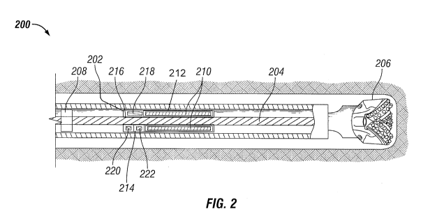
Figure 2 is a diagram of a portion of an example RSS 200, according to aspects
of
the present disclosure. In the embodiment shown, the RSS 200 comprises an
outer housing 202
and a drive shaft 204 at least partially within and rotationally independent
from the outer housing
202. The drive shaft 204 may be coupled to a drill bit 206 at one end and to a
torque source (not
shown) at the other end. Example torque sources include a downhole motor and a
drill string
rotated form the surface by a top drive. During drilling operations, the
torque source may rotate
the drive shaft 204, which in turn rotates the drill bit 206 and causes the
drill bit 206 to bore into
a formation, while the outer housing 202 may remain generally non-rotating. In
the embodiment
shown, the longitudinal axis of the drill bit 206 may be altered using a
deflection assembly 208,
such as eccentric rings, coupled to the outer housing 202 to radially deflect
the drive shaft 204
within the housing 202 during operation.
According to aspects of the present disclosure, the RSS 200 may comprise at
least
one gamma ray sensor 210 rotationally coupled to the drive shaft 204 within
the outer housing
202. The at least one gamma ray sensor 210 may comprise any gamma ray sensor
type typically
used for downhole measurements, as would be appreciated by one of ordinary
skill in the art in
view of this disclosure. Example sensors include one or more Geiger-Miiller
tubes, and a
photosensor matrix scintillating crystal with one or more optical sensors such
as a photo
multiplier tube, photocell, PIN diode, photodiode or a quantum dot graphene
based photon
sensor.
In the embodiment shown, the at least one gamma ray sensor 210 comprises a
plurality of gamma ray sensors located within at least one pressurized cavity
212 in a housing
214. The at least one pressurized cavity 212 may be maintained at an
atmospheric pressure to
ensure proper functionality of the sensor 210. In certain embodiments, the
plurality of gamma
ray sensors 210 may be spaced at equal angular intervals around the housing
214, or bunched
7
CA 02965630 2017-04-24
WO 2016/105406 PCT/US2014/072325
together to provide measurements with improved directional sensitivity.
Additionally, the
plurality of gamma ray sensors 210 may be located within a plurality of
pressurized cavities
spaced at equal angular intervals around the housing 214, as will be described
in detail below.
In the embodiment shown, the sensors 210 are longitudinally parallel with the
outer housing 202 and comprise the same length. As would be appreciated by one
of ordinary
skill in the art in view of this disclosure, the sensitivity of a gamma ray
sensor may positivity
correlate with its size. Accordingly, length of the sensors 210 and the
housing 214/pressure
cavity 212 to accommodate the sensors 210 may be scaled based on the
measurement sensitivity
required and the physical constraints of the RSS 200. In other embodiments,
the lengths of the
sensors 210 may be non-uniform and/or the sensors 210 may be oriented
differently within the
housing 214.
The housing 214 may be rotationally coupled to the drive shaft 204 such that
the
housing 212 and the gamma ray sensors 210 rotate with the same speed and
direction as the drive
shaft 204. In the embodiment shown, the housing 214 is rotationally coupled to
the drive shaft
204 via a series of longitudinal splines 216 formed on the outer surface of
the drive shaft 204 and
the inner surface of the housing 214. The use of the housing 214 and splines
216 to rotationally
couple the gamma ray sensors 210 to the drive shaft 204 is not intended to be
limiting, as other
mechanisms may be used.
In the embodiment shown, the sensors 210 and housing 212 are located on the
drill bit side of the deflection assembly 208 to allow the sensors 210 to be
positioned closer to
the drill bit 206. This may improve the accuracy of the resulting measurements
and the speed
with which resulting steering decisions may be made. In other embodiments, the
sensors 210
may be located at other positions along the drive shaft 204, including on the
opposite side of the
deflection assembly 208 from the drill bit 206.
The housing 210 may further include electronics associated with the sensors
210.
The electronics may include at least one of a control unit 218, a power source
220, and a position
sensor 222. The power source 220 may comprise, for example, a battery pack or
a capacitor
bank. In other embodiments, the power source 220 may be located outside of the
housing 214
and power may be provided to the housing through one or more electrical
couplings (not shown),
such as an inductive coupling between the housing 214 and the outer housing
202. The position
sensor 222 may comprise, for example, an accelerometer, a magnetometer, or any
other sensor
that can be used to identify the rotational position of the housing 214 within
a borehole, as would
be appreciated by one of ordinary skill in the art in view of this disclosure.
In certain
8
CA 02965630 2017-04-24
WO 2016/105406 PCT/US2014/072325
embodiments, the position sensor 222 may draw as a reference the rotational
position of the
outer housing 202, which may remain substantially non-rotating during use.
The control unit 218 may be coupled to the power source 220, position sensor
222, and gamma ray sensors 210. The control unit 218 may draw power from the
power source
220 and receive measurements from both the position sensor 222 and the gamma
ray sensors
210, and may process the measurements received from the gamma ray sensors 210
using the
measurement received from the position sensor 222, as will be described below.
The control unit
218 may include a processor, examples of which include microprocessors,
microcontrollers,
digital signal processors (DSP), application specific integrated circuit
(ASIC), or any other
digital or analog circuitry configured to interpret and/or execute program
instructions and/or
process data. The control unit 218 may further comprise a memory element
communicably
coupled to the processor. The processor may be configured to interpret and/or
execute program
instructions and/or data stored in memory. Example memory elements comprise
non-transitory
computer readable media that may include any system, device, or apparatus
configured to hold
and/or house one or more memory modules; for example, memory may include read-
only
memory, random access memory, solid state memory, or disk-based memory. Each
memory
module may include any system, device or apparatus configured to retain
program instructions
and/or data for a period of time (e.g., computer-readable non-transitory
media).
Figure 3 is a diagram of example gamma ray sensors 300 within a housing 302,
according to aspects of the present disclosure. In the embodiment shown, the
housing 302
comprises an inner sleeve 304 rotationally coupled to a drive shaft 306 of a
RSS, and an outer
sleeve 308 rotationally coupled to the inner sleeve 304. The inner sleeve 304
may be rotationally
coupled to the drive shaft 306 through a plurality of splines 310 formed on an
inner surface of
the inner sleeve 304 and an outer surface of the drive shaft 306. The outer
sleeve 308 may be
rotationally coupled to the inner sleeve 304 through brackets (not shown) or
any other
attachment mechanism that would be appreciated by one of ordinary skill in the
art in view of
this disclosure. The inner sleeve 304 and the outer sleeve 308 may at least
partially define at
least one pressure cavity 312 in which the gamma ray sensors 300 are located.
In other
embodiments, the at least one pressure cavity 312 may comprise a plurality of
pressure cavities
defined, in part, by features of the inner housing 304 and/or the outer
housing 308, in which the
plurality of gamma ray sensors 300 are angularly spaced.
Figure 4 is a diagram of an example housing 400 comprising an inner sleeve 402
= and an outer sleeve 404, according to aspects of the present disclosure.
In the embodiment
9
CA 02965630 2017-04-24
WO 2016/105406 PCT/US2014/072325
shown, the inner sleeve 402 and outer sleeve 404 both have circular cross-
sections and cooperate
to at least partially define a single, annular pressure cavity 406 in which
the plurality of gamma
ray sensors 408 are angularly spaced. The angular spacing may comprise a
uniform angular
interval, as shown. In other embodiments, the angular spacing may be non-
uniform, for
example, with sensors 408 grouped together at a first angular interval, and
the groups of the
sensors 406 spaced around the housing 400 at a second angular interval.
Figure 5 is a diagram of another example housing 500 comprising an inner
sleeve
502 and an outer sleeve 504, according to aspects of the present disclosure.
In the embodiment
shown, the inner sleeve 502 comprises a square cross-section and the outer
sleeve 504 comprises
a circular cross-section. The inner sleeve 502 and outer sleeve 504 still
cooperate to form a
single pressure cavity 506, but the cavity comprises a non-uniform shape due
to the square cross-
section of the inner sleeve 502. Due to the non-uniform shape of the pressure
cavity 506, the
gamma ray sensors 508 may be separated into groups spaced around the housing
500. The
spacing of the groups and the spacing of the sensors 508 within the groups may
provide an
improved directional resolution to measurements generated by the sensors 508.
Figure 6 is a diagram of another example housing 600 comprising an inner
sleeve
602 and an outer sleeve 604, according to aspects of the present disclosure.
In the embodiment
shown, the inner sleeve 602 comprises a plurality of ribs 610 extending
radially outward from
the center of the inner sleeve 602. The ribs 610 may be positioned at equal
angular intervals
.. around the inner sleeve 602, or with any other angular spacing. In certain
embodiments, the ribs
610 may contact and seal against the outer sleeve 604 to form a plurality of
pressure cavities
within the housing 600. In other embodiments, as shown, the ribs 610 may not
seal against the
outer sleeve 604, instead forming a plurality of pockets within a single
pressure cavity 608.
Like the housing described with reference to Fig. 5, the non-uniform spacing
of
the sensors 608 caused by the presence of the ribs 610 may provide an improved
directional
resolution to measurements generated by the sensors 608. In certain
embodiments, the inner
sleeve 604 may comprise a gamma ray shielding or absorbing material 612 to
focus the angular
sensitivity and directionality of the sensors 608. In the embodiment shown,
the gamma ray
shielding or absorbing material 612 is deposited in a thin layer on the outer
surface of the inner
sleeve 602 such that the angular sensitivity of each group of sensors 608 is
focused outwards,
away from the gamma ray shielding or absorbing material 612. Example gamma ray
shielding
or absorbing materials include materials with a high electron/mass density,
such as lead, that can
be deposited in a thin layer without significantly reduce the clearance for
the sensors within the
CA 02965630 2017-04-24
WO 2016/105406 PCT/US2014/072325
housing, and Graded-Z shielding, a laminate composed of a gradient of high to
low density
materials. Similar gamma ray shielding may be used with any of the embodiments
described
herein, including applying the gamma ray shielding to any of the inner and/or
outer sleeve
configurations described herein. Additionally, the gamma ray shielding may be
applied in short
angular segments on the inner and/or outer sleeve to increase the angular
sensitivity of the
resulting measurements.
Although the embodiments of the housing described above include different
cross
sections and features on the inner sleeve to facilitate angularly focused
measurements by the
gamma ray sensors, it is also possible that such cross-sections and features
may be located the
outer sleeve. For example, the ribs 610 in Fig. 6 may be formed on an inner
surface of the outer
sleeve 604, rather than on an outer surface of the inner sleeve 602.
Additionally, separate
elements, such as separately formed ribs, may be inserted between the inner
and outer sleeves.
When in use, a RSS similar to the ones described above may be located within a
subterranean formation, where measurements may be taken by the gamma ray
sensors. The
measurements may be taken, for example, when the gamma ray sensors are
rotating with the
drive shaft, or when the drive shaft is temporarily halted and the gamma ray
sensors are
stationary. Those measurements may be received at a control unit associated
with the gamma
ray sensors along with position information, and processed and/or collected by
the control unit
and transmitted to a surface information handling system through a telemetry
system coupled to
the RSS. The surface information handling system may determine one or more
formation
characteristics based, at least in part, on the received measurements. Example
formation
characteristics include the type of rock in the formation immediately
surrounding a drill bit
coupled to the RSS, which may be used to determine where formation boundaries
are and how to
steer the drill bit. In other embodiments, the measurements may be transmitted
to a separate
control unit within the RSS that may determine one or more formation
characteristics based, at
least in part, on the received measurements and make automatic steering
decisions based, at least
in part, on the determined formation characteristic.
In certain embodiments, the measurements generated by the gamma ray sensors
may comprise bulk gamma ray measurements. Bulk gamma ray measurements may be
.. generated while the gamma ray sensors are rotating or non-rotating with the
drive shaft. Each
gamma ray sensor may sense gamma rays emitted by the formation in all angular
orientations
with respect to the drive shaft. The resulting measurements from each of the
plurality of gamma
ray sensors may be aggregated to identify a total or average gamma ray
measurement for a
11
CA 02965630 2017-04-24
WO 2016/105406 PCT/US2014/072325
particular depth of the formation. The total or average gamma ray measurement
may be used to
identify trends in radiation level at the RSS, which may indicate a change in
the composition of
the formation near the drill bit such that drilling needs to be halted or the
drilling direction
altered. Additionally, it may indicate the need to take directional
measurements, described
below, to determine if the increasing radiation level is attributable to all
of the formation at that
depth range or to a radiation source located in a particular angular
orientation with respect to the
RSS, which may be the case, for example, when the drill bit is near a
formation boundary.
In certain embodiments, directional measurements may be taken with the gamma
ray sensors both while the gamma ray sensors are rotating with the drive shaft
and while the
gamma ray sensors are temporarily halted. When temporarily halted, the
measurements from the
gamma ray sensors may be correlated with position sensor data to identify the
angular
orientation around the drive shaft that corresponds to the gamma ray
measurements. The angular
orientations may be divided into "bins" that each correspond to a range of
angular orientations
with respect to the drive shaft. The size of the bins/range of angular
orientation may be arbitrary
or may depend, in part, on the directionality of the gamma ray sensors coupled
to the drive shaft.
For example, each bin may comprise a 90 quadrant surrounding the RSS,
corresponding to the
configuration of Fig. 6 in which the gamma ray sensors are divided into four
equally space
pockets around the housing. Other bin sizes are possible, including non-
uniform bin. Similar
binning techniques may be used when the gamma ray sensors are rotating. In
those instances,
however, the delay time between when a gamma ray is transmitted and received,
and the
rotational speed of the gamma ray sensor may skew the correspondence between
the angular
orientation in which the gamma ray was emitted and the angular orientation of
the gamma ray
sensors when the gamma ray was detected. Accordingly, the angular orientation
of the gamma
ray measurements may be corrected before they are associated with a particular
bin.
According to aspects of the present disclosure, an example apparatus includes
an
outer housing and a drive shaft at least partially within and rotationally
independent from the
outer housing. A drill bit may be coupled to the drive shaft. At least one
gamma ray sensor may
be rotationally coupled to the drive shaft within the outer housing. In
certain embodiments, the
apparatus further includes a housing rotationally coupled to the drive shaft,
wherein the housing
comprises at least one pressurized cavity; and the at least one gamma ray
sensor is located within
the at least one pressurized cavity.
In certain embodiments, the housing comprises an inner sleeve rotationally
coupled to the drive shaft and an outer sleeve rotationally coupled to the
inner sleeve; and the
12
CA 02965630 2017-04-24
WO 2016/105406 PCT/US2014/072325
inner sleeve and outer sleeve at least partially define the at least one
pressure cavity. In certain
embodiments, the inner sleeve comprises at least one of a circular and a
square cross section. In
certain embodiments, the inner sleeve and the outer sleeve at least partially
define a plurality of
pressure cavities angularly spaced around the housing.
In any of the embodiments described in the preceding two paragraphs, at least
one
of the inner sleeve and the outer sleeve may comprise a gamma shielding
material. In any of the
embodiments described in the preceding two paragraphs, the housing may be
rotationally
coupled to the drive shaft through splines. In any of the embodiments
described in the preceding
two paragraphs, the at least one gamma ray sensor may comprise a plurality of
gamma ray
sensors angularly spaced within the housing and oriented in parallel with the
longitudinal axis of
the outer housing. In any of the embodiments described in the preceding two
paragraphs, at least
one of a control unit, a power source, and a position sensor associated with
the at least one
sensor may be coupled to the housing. In any of the embodiments described in
the preceding
two paragraphs, the at least one gamma ray sensor may comprise at least one of
a Geiger-MUller
.. tube and a scintillator crystal coupled to an optical sensor.
According to aspects of the present disclosure, an example method includes
positioning a rotary steerable system (RSS) within a subterranean formation,
wherein the rotary
steerable system comprises a drive shaft at least partially within and
rotationally independent
from an outer housing. A measurement taken by at least one gamma ray sensor
rotationally
coupled to the drive shaft within the outer housing may be received, and a
characteristic of the
formation may be determined based, at least in part, on the received
measurement. In certain
embodiments, receiving the measurement taken by at least one gamma ray sensor
rotationally
coupled to the drive shaft within the outer housing comprises receiving
measurements taken by a
plurality of gamma ray sensors located within at least one pressurized cavity
in a housing
rotationally coupled to the drive shaft. In certain embodiments, the housing
comprises an inner
sleeve rotationally coupled to the drive shaft and an outer sleeve
rotationally coupled to the inner
sleeve; and the inner sleeve and outer sleeve at least partially define the at
least one pressure
cavity.
In any of the embodiments described in the preceding paragraph, receiving the
.. measurement taken by at least one gamma ray sensor rotationally coupled to
the drive shaft may
comprise receiving the measurement taken by at least one gamma ray sensor
while the drive
shaft is rotating. In certain embodiments, the measurement comprises
measurements taken by
the at least one gamma ray sensor in all angular orientations with respect to
the drive shaft. In
13
CA 02965630 2017-04-24
WO 2016/105406 PCT/US2014/072325
certain embodiments, determining the characteristic of the formation based, at
least in part, on
the received measurement comprises determining a total or average measurement
associated with
a depth of the formation at which the measurement was taken. In certain
embodiments,
determining the characteristic of the formation based, at least in part, on
the received
measurement comprises dividing the measurements into a plurality of bins, each
comprising a
range of angular orientations surrounding the RSS. In certain embodiments,
dividing the
measurements into a plurality of bins, each comprising a range of angular
orientations
surrounding the RSS comprises correcting each measurement based, at least in
part, on the
rotating speed of the at least one gamma ray sensor.
In any of the embodiments described in the preceding two paragraphs, receiving
the measurement taken by at least one gamma ray sensor rotationally coupled to
the drive shaft
may comprise receiving the measurement taken by at least one gamma ray sensor
while the drive
shaft is not rotating. In certain embodiments, determining the characteristic
of the formation
based, at least in part, on the received measurement comprises at least one of
dividing the
measurement into one of a plurality of bins, each comprising a range of
angular orientations
surrounding the RSS; and determining a total or average measurement associated
with a depth of
the formation at which the measurement was taken.
Therefore, the present disclosure is well adapted to attain the ends and
advantages
mentioned as well as those that are inherent therein. The particular
embodiments disclosed
above are illustrative only, as the present disclosure may be modified and
practiced in different
but equivalent manners apparent to those skilled in the art having the benefit
of the teachings
herein. Furthermore, no limitations are intended to the details of
construction or design herein
shown, other than as described in the claims below. It is therefore evident
that the particular
illustrative embodiments disclosed above may be altered or modified and all
such variations are
considered within the scope and spirit of the present disclosure. Also, the
terms in the claims
have their plain, ordinary meaning unless otherwise explicitly and clearly
defined by the
patentee. The indefinite articles "a" or "an," as used in the claims, are
defined herein to mean
one or more than one of the element that it introduces. Additionally, the
terms "couple" or
"coupled" or any common variation as used in the detailed description or
claims are not intended
to be limited to a direct coupling. Rather two elements may be coupled
indirectly and still be
considered coupled within the scope of the detailed description and claims.
14