Note: Descriptions are shown in the official language in which they were submitted.
CA 02965837 2017-04-25
WO 2016/069386 PCT/US2015/057048
DRUM BRAKE S-CAM HAVING OFFSET CAM FOLLOWERS
BACKGROUND OF THE INVENTION
a. Field of the Invention
100011 This invention relates to vehicle brakes. In particular, the
invention relates to a drum
brake in which the brake actuating means engages the brake shoes at offset
positions to improve the
direction of the brake actuating forces.
b. Background Art
[0002] Referring to Figure 1, a conventional prior art drum brake 10 is
illustrated. In a
conventional drum brake, a drum 12 rotates with a wheel or wheels proximate to
one end of an axle.
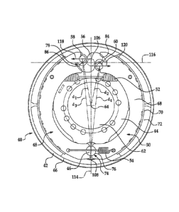
The drum 12 defines a radially inner braking surface 14. A brake spider 16 is
disposed about the
axle and a pair of brake shoes 18, 20 are pivotally mounted at one end to the
brake spider 16. The
opposite end of each brake shoe 18, 20 is engaged by an actuating member such
as a cam 22 to
move the brake shoes 18, 20 between positions of engagement and disengagement
with the braking
surface of the brake drum.
[0003] In a conventional S-cam drum brake as shown in Figure 1, rollers 24,
26, or cam
followers, are disposed between the brake shoes 18, 20 and the cam 22 to
transfer brake application
forces from the cam 22 to the brake shoes 18, 20. Force is applied by the cam
22 through the rollers
24, 26 along the direction indicated by arrows 28, 30, respectively, which
extend from a "power
circle" of the cam 22 defined by a radius from the rotational axis of the
generally involute cam 22.
The force vector represented by arrows 28, 30 may be resolved into two
components--a component
represented by arrows 32, 34 comprising the effective brake actuation force
tangent to the pivot arc
of the corresponding brake shoe 18, 20 and a component represented by arrows
36, 38 comprising
the divergence between the direction of the force exerted by the cam 22 on
rollers 24, 26 and the
effective brake actuation force.
[0004] The divergence between the actuating forces applied by the cam 22
and represented
by arrows 28, 30 and the effective brake actuating force represented by arrows
32, 34 has several
drawbacks. First, the force component represented by arrows 36, 38 creates
mechanical stress in
1
CA 02965837 2017-04-25
WO 2016/069386 PCT/US2015/057048
the webs of the brakes shoes 18, 20 and is particularly acute when the force
component 36, 38 is
directed outward in trailing brake shoes. The increased stress can lead to
cracks in the brake shoe
webs and costly downtime and repairs. Second, the actuation efficiency of the
brake 10 is less than
optimal because the effective brake actuation force is less than the force
exerted by the cam 22. As
a result, more fluid pressure is required to actuate the brake leading to
relatively large air chambers
in brake actuators and/or requiring brake linings with relatively high
friction coefficients. Third, the
amount of rotation of cam 22 and, therefore, the displacement of brakes shoes
18, 20, is relatively
limited thereby limiting the potential thickness of the brake linings and
requiring more frequent
maintenance and/or repair.
[0005] The inventor herein has recognized a need for a brake that will
reduce one or more of
the above-identified deficiencies and/or provide improved performance.
BRIEF SUMMARY OF THE INVENTION
[0006] This invention relates to vehicle brakes. In particular, the
invention relates to a drum
brake in which the brake actuating means engages the brake shoes at offset
positions to improve the
direction of the brake actuating forces.
[0007] A brake in accordance with one embodiment of the invention includes
a brake spider
having a central aperture configured to receive an axle extending therethrough
along a center axis of
the central aperture. The brake further includes first and second brake shoes.
Each of the first and
second brakes shoes has a first end pivotally coupled to the brake spider. The
brake further
includes a first circular cam follower disposed at a second end of the first
brake shoe, a second
circular cam follower disposed at a second end of the second brake shoe and a
cam in engagement
with the first and second circular cam followers. Movement of the cam causes
the first and second
brake shoes to move between positions of engagement and disengagement with an
associated
braking surface. A center of the first circular cam follower is disposed at a
first distance from the
center axis and a center of the second circular cam follower is disposed at a
second distance from
the center axis, the first distance different from the second distance.
2
CA 02965837 2017-04-25
WO 2016/069386 PCT/US2015/057048
[0008] A brake in accordance with another embodiment of the invention
includes a brake
spider having a central aperture configured to receive an axle extending
therethrough along a center
axis of the central aperture. The brake further includes first and second
brake shoes. Each of the
first and second brakes shoes has a first end pivotally coupled to the brake
spider. The brake further
includes means, in engagement with a second end of the first brake shoe and a
second end of the
second brake shoe, for moving the first and second brake shoes between
positions of engagement
and disengagement with an associated braking surface. A distance between the
center axis and a
radially outermost point of engagement between the first brake shoe and the
moving means is
different from a distance between the center axis and a radially outermost
point of engagement
between the second brake shoe and the moving means.
[0009] A brake in accordance with another embodiment of the invention
includes a brake
spider having a central aperture configured to receive an axle extending
therethrough along a center
axis of the central aperture. The brake further includes first and second
brake shoes. Each of the
first and second brakes shoes has a first end pivotally coupled to the brake
spider. The brake further
includes a first circular cam follower disposed at a second end of the first
brake shoe, a second
circular cam follower disposed at a second end of the second brake shoe and a
cam in engagement
with the first and second circular cam followers. Movement of the cam about a
rotational axis
causing the first and second brake shoes to move between positions of
engagement and
disengagement with an associated braking surface. A center of the first
circular cam follower is
disposed on a first side of a first plane extending perpendicular to a second
plane containing the
center axis and the rotational axis and a center of the second circular cam
follower is disposed on a
second side of the first plane.
[0010] A brake in accordance with the invention represents an improvement
as compared to
conventional brakes. In particular, by adjusting the position of the cam
followers and offsetting the
cam followers, the force applied by the cam to the cam followers and brake
shoes may be
substantially tangent to the pivot arc of the brake shoes and reduces any
divergence between the
effective brake actuation force and the force applied by the cam. As a result,
mechanical stress in
the brake shoes webs is reduced as well as downtime and repair costs resulting
from web cracking.
3
CA 02965837 2017-04-25
The actuation efficiency of the brake is also increased enabling a reduction
in the air
chamber size for the brake actuator and/or the use of brake linings with lower
coefficients of
friction. The inventive brake also allows increased travel of the cam
followers and allows the
brake shoes to retract further thereby permitting the use of thicker brake
linings and
improving the life of the brake shoes.
[0010a] In one aspect, there is provided a brake, comprising: a brake
spider having a
central aperture configured to receive an axle extending therethrough along a
center axis of the
central aperture; first and second brake shoes, each of said first and second
brakes shoes having a
web having a first end pivotally coupled to said brake spider and a second
end; a first circular
cam follower disposed at said second end of said web of said first brake shoe
between a radially
innermost point and a radially outermost point of said second end of said web
of said first brake
shoe, said first circular cam follower fixed against movement in a radial
direction relative to said
second end of said web of said first brake shoe; a second circular cam
follower disposed at said
second end of said web of said second brake shoe between a radially innermost
point and a
radially outermost point of said second end of said web of said second brake
shoe, said second
circular cam follower fixed against movement in a radial direction relative to
said second end of
said web of said second brake shoe; and, an S-cam configured to rotate about a
rotational axis
and having a first lobe in engagement with said first circular cam follower
along a first surface
and a second lobe in engagement with said second circular cam follower along a
second surface,
movement of said cam causing said first and second brake shoes to move between
positions of
engagement and disengagement with an associated braking surface, wherein a
first plane
extending through said first surface and parallel to a plane containing said
center axis and said
rotational axis does not intersect any other portion of said first lobe of
said S-cam or said first
4
CA 02965837 2017-04-25
cam follower and a second plane extending through said second surface and
parallel to said plane
containing said center axis and said rotational axis does not intersect any
other portion of said
second lobe of said S-cam or said second cam follower wherein a center of said
first circular cam
follower is disposed at a first distance from said center axis and a center of
said second circular
cam follower is disposed at a second distance from said center axis, said
first distance different
from said second distance.
[0010b] In another aspect, there is provided a brake, comprising: a brake
spider having a
central aperture configured to receive an axle extending therethrough along a
center axis of the
central aperture; first and second brake shoes, each of said first and second
brakes shoes having a
first end pivotally coupled to said brake spider; a first circular cam
follower disposed at a second
end of said first brake shoe; a second circular cam follower disposed at a
second end of said
second brake shoe; and, a cam in engagement with said first and second
circular cam followers,
movement of said cam causing said first and second brake shoes to move between
positions of
engagement and disengagement with an associated braking surface wherein a
center of said first
circular cam follower is disposed at a first distance from said center axis
and a center of said
second circular cam follower is disposed at a second distance from said center
axis, said first
distance different from said second distance wherein each of said first and
second brake shoes
includes a web; and, a brake table supported on said web wherein a first end
of said web defines
radially inner and outer recesses configured to receive a corresponding one of
said first and
second circular cam followers, said web of said first brake shoe receiving
said first circular cam
follower in said radially outer recess, said web of said second brake shoe
receiving said second
circular cam follower in said radially inner recess.
4a
CA 02965837 2017-04-25
100 1 OCI In another aspect, there is provide a brake, comprising: a brake
spider having a
central aperture configured to receive an axle extending therethrough along a
center axis of the
central aperture; first and second brake shoes, each of said first and second
brakes shoes having a
web having a first end pivotally coupled to said brake spider and a second
end; a first circular
cam follower disposed at a said second end of said web of said first brake
shoe between a
radially innermost point and a radially outermost point of said second end of
said web of said
first brake shoe, said first circular cam follower fixed against movement in a
radial direction
relative to said second end of said web of said first brake shoe; a second
circular cam follower
disposed at said second end of said web of said second brake shoe between a
radially innermost
point and a radially outermost point of said second end of said web of said
second brake shoe,
said second circular cam follower fixed against movement in a radial direction
relative to said
second end of said web of said second brake shoe; and, an S-cam configured to
rotate about a
rotational axis and having a first lobe in engagement with said first circular
cam follower along a
first surface and a second lobe in engagement with said second circular cam
follower along a
second surface, movement of said cam about said rotational axis causing said
first and second
brake shoes to move between positions of engagement and disengagement with an
associated
braking surface, wherein a first plane extending through said first surface
and parallel to a plane
containing said center axis and said rotational axis does not intersect any
other portion of said
first lobe of said S-cam or said first cam follower and a second plane
extending through said
second surface and parallel to said plane containing said center axis and said
rotational axis does
not intersect any other portion of said second lobe of said S-cam or said
second cam follower
wherein a center of said first circular cam follower is disposed on a first
side of a third plane
4b
CA 02965837 2017-04-25
extending perpendicular to said plane containing said center axis and said
rotational axis and a
center of said second circular cam follower is disposed on a second side of
said third plane.
[0010d] In another aspect, there is provided a brake, comprising: a brake
spider having a
central aperture configured to receive an axle extending therethrough along a
center axis of the
central aperture; first and second brake shoes, each of said first and second
brakes shoes having a
first end pivotally coupled to said brake spider; a first circular cam
follower disposed at a second
end of said first brake shoe; a second circular cam follower disposed at a
second end of said
second brake shoe; and, a cam in engagement with said first and second
circular cam followers,
movement of said cam about a rotational axis causing said first and second
brake shoes to move
between positions of engagement and disengagement with an associated braking
surface wherein
a center of said first circular cam follower is disposed on a first side of a
first plane extending
perpendicular to a second plane containing said center axis and said
rotational axis and a center
of said second circular cam follower is disposed on a second side of said
first plane wherein each
of said first and second brake shoes includes: a web; and, a brake table
supported on said web
wherein a first end of said web defines radially inner and outer recesses
configured to receive a
corresponding one of said first and second circular cam followers, said web of
said first brake
shoe receiving said first circular cam follower in said radially outer recess,
said web of said
second brake shoe receiving said second circular cam follower in said radially
inner recess.
[0011] The foregoing and other aspects, features, details, utilities, and
advantages of
the present invention will be apparent from reading the following description
and claims,
and from reviewing the accompanying drawings.
4c
CA 02965837 2017-04-25
BRIEF DESCRIPTION OF THE DRAWINGS
[0012] Figure 1 is a plan view of a prior art brake.
[0013] Figure 2 is a plan view of a brake in accordance with one embodiment
of the
present teachings.
[0014] Figure 3 is a plan view of a brake in accordance with another
embodiment of the
present teachings.
[0015] Figure 4 is an enlarged view of one end of a web for a brake shoe in
accordance
with the present teachings.
DETAILED DESCRIPTION OF THE INVENTION
[0016] Referring now to the drawings wherein like reference numerals are
used to
identify identical components in the various views, Figure 2 illustrates a
brake 40 in
accordance with one embodiment of the present invention. Brake 40 is provided
to slow
rotation of one or more vehicle wheels. Brake 40 is particularly adapted for
use in heavy
vehicles. It should be understood, however, that brake 40 may be used on a
wide variety of
vehicles and in non-vehicular applications. Brake 40 is configured to act
against an annular
brake drum 42 that rotates with the vehicle wheel or wheels at one end of an
axle (not
shown). Brake 40 may include a brake spider 44, one or more anchor pins 46,
brake shoes 48,
50, return and retaining springs 52, 54, and means, such as cam 56
4d
CA 02965837 2017-04-25
WO 2016/069386 PCT/US2015/057048
and rollers or cam followers 58, 60, for moving brake shoes 48, 50 between
positions of
engagement and disengagement with a braking surface.
[0017] Spider 44 is provided to mount the various components of brake 40.
Spider 44 defines
a central aperture 62 having a center axis 64 which may be coincident with the
rotational axis of the
vehicle wheel. The aperture 62 is configured to receive a vehicle axle
extending therethrough and
along axis 64. Spider 44 may further define bores (not shown) on either side
of aperture 62
configured to receive anchor pin 46 and a camshaft (not shown) supporting cam
56.
[0018] Anchor pin 46 is provided to pivotally mount brake shoes 48, 50 to
brake spider 44.
Anchor pin 46 may comprise a round pin and may be mounted on and extend from
brake spider 44.
Referring to Figure 3, in an alternative embodiment, a brake 40 may include
multiple anchor pins
46 with each of brake shoes 48, 50 pivotally coupled to a separate anchor pin
46.
[0019] Brake shoes 48, 50 are provided for selective engagement with a
braking surface 66 of
drum 42 in order to apply a braking torque to the drum and one or more vehicle
wheels. Brake
shoes 48, 50 may together comprise a brake shoe kit adapted for use in brake
40 or 40'. Brake shoes
48, 50 are supported on anchor pin(s) 46 and thereby pivotally coupled to
spider 44 at one end.
Each brake shoe 48, 50 may include one or more webs 68, a brake table 70, and
one or more brake
linings 72.
[0020] Webs 68 support brake table 70. Webs 68 may also provide a
connection point for
return spring 52 and retaining spring 54. Webs 68 may be made from metals and
metal alloys such
as steel. Webs 68 are arcuate in shape and extend between opposite ends of
brake shoes 48, 50. It
should be understood that the number of webs 68 in each brake 48, 50 may vary
and each brake
shoe 48, 50 may therefore include a plurality of webs 68 that extend generally
parallel to one
another. Webs 68 may be secured to brake table 70 using welds or other
conventional fastening
means. Each web 68 may have one end 74 that defines a semicircular recess 76
configured to
receive a corresponding anchor pin 46. In accordance with one aspect of the
present teachings, the
opposite end 78 of each web 68 may be configured to engage rollers 58, 60 at
either of first and
second radially offset positions. Referring to Figure 4, end 78 of web 68 may
be divided into a
plurality of radially offset portions such as portions 80, 82. Each portion
80, 82 may be configured
CA 02965837 2017-04-25
WO 2016/069386 PCT/US2015/057048
to engage a roller 58, 60 and thereby locate rollers 58, 60 at corresponding
radially offset positions.
For example, web 68 may define one more semicircular recesses 84, 86
configured to receive rollers
58, 60 with each portion 80, 82 including a corresponding recess 84, 86. End
78 of web 68 may
further define a radially extending edge 88 having radially inner and outer
ends 90, 92. Recesses
84, 86 may be formed along edge 88 and may be disposed between ends 90, 92 of
edge 88.
Recesses 84, 86 each define radially innermost and radially outermost points
of engagement 94, 96
and 98, 100, respectively, for rollers 58, 60 and a radially center point of
engagement 102, 104,
respectively, approximately midway between the corresponding radially
innermost and outermost
points of engagement 94, 96 and 98, 100. Referring to Figures 2-3, rollers 58,
60 may be positioned
such that roller 58 is received within recess 84 of web 68 of brake shoe 48
while roller 60 is
received within recess 86 of web 68 of brake shoe 50. As a result, and with
reference to Figure 4,
the distance in brake shoe 48 between the radially inner end 90 of edge 88 and
the radially center
point of engagement 102 of web 68 of brake shoe 48 and roller 58 is different
than the distance in
brake shoe 50 between the radially inner end 90 of edge 88 and the radially
center point of
engagement 104 of web 68 of brake shoe 50 and roller 60. Similarly, the
distance in brake shoe 48
between the radially outer end 92 of edge 88 and the radially center point of
engagement 102 of
web 68 of brake shoe 48 and roller 58 is different than the distance in brake
shoe 50 between the
radially outer end 92 of edge 88 and the radially center point of engagement
104 of web 68 of brake
shoe 50 and roller 60.
[0021] In the embodiments illustrated in Figures 2 and 3, the webs 68 of
each brake shoe 48,
50 are identical in construction such that the webs 68 and brake shoes 48, 50
are interchangeable
within brake 40 or 40'. In particular, each web 68 contains recesses 84, 86
with recess 84 disposed
radially outward of recess 86. In an alternative embodiment, however, the
web(s) 68 of brakes
shoes 48, 50--and particularly the shape of ends 78 of brake webs 68--may
differ. For example, the
web(s) 68 of brake shoe 48 may include only one of recesses 84, 86--such as
radially outer recess
84--while the web(s) 68 of brake shoe 50 include the other of recesses 84, 86--
such as radially inner
recess 86.
6
CA 02965837 2017-04-25
WO 2016/069386 PCT/US2015/057048
[0022] Brake table 70 is provided to support brake linings 72. Table 70 is
supported on webs
68 and may be arcuate in shape. Table 70 may be made from conventional metals
and metal alloys
including steel.
[0023] Brake linings 72 are provided for frictional engagement with braking
surface 66 of
drum 42. Linings 72 may be made from conventional friction materials. Brake
linings 72 are
disposed on brake table 70 and may be secured to brake table 70 using a
plurality of rivets or other
conventional fasteners.
[0024] Return spring 52 is provided to bias brake shoes 48, 50 to a
position of disengagement
from the braking surface 66 of drum 42. Retainer springs 54 are provided to
retain brake shoes 48,
50¨and particularly webs 68¨on anchor pin(s) 46. Springs 52, 54 are
conventional in the art.
The ends of spring 52 may engage pins (not shown) extending from webs 68 of
brakes shoes 48, 50
while the ends of springs 54 extend through corresponding apertures in webs 68
of brake shoes 48,
50.
[0025] Cam 56, together with rollers 58, 60, provides an actuating assembly
or means for
moving brake shoes 48, 50 between positions of engagement with and
disengagement from the
braking surface 66 of the drum 42. In the illustrated embodiment, cam 56
comprises a doubled
lobed S-cam that engages rollers 58, 60. Cam 56 is connected to one end of a
camshaft (not shown)
and rotates about a rotational axis 106 responsive to forces imposed by a
brake actuator (not shown)
on the camshaft.
[0026] Rollers 58, 60 are provided to transfer brake actuation forces from
cam 56 to brake
shoes 48, 50. Rollers 58, 60 are circular in cross-section and are configured
to be received within
recesses 84, 86 of webs 68 formed at end 78 of shoes 48, 50, respectively.
Rollers 58, 60 engage
webs 68 and cam 56 and follow the surface of the cam 56 as it rotates thereby
causing shoes 48, 50
to pivot about a pivot axis 108 (Figure 2) or axes 110, 112 (Figure 3) defined
at the center of anchor
pins 46. In accordance with the present invention, rollers 58, 60 are offset
from one another. A
plane 114 contains both axis 64 and the rotational axis 106 of cam 56.
Referring to Figure 2, plane
114 may also contain the pivot axis 108 at the center of anchor pin 46.
Alternatively, and with
reference to Figure 3, in embodiments where multiple anchor pins 46 are
employed the pivot axes
7
CA 02965837 2017-04-25
WO 2016/069386
PCT/US2015/057048
110, 112 of the anchor pins 46 may be equidistant from plane 114 on either
side of plane 114.
Another plane 116 containing rotational axis 106 of cam 56 extends
perpendicular to plane 114.
The center of roller 58 is disposed on one side of plane 116 while the center
of roller 60 is disposed
on the other side of plane 116. Further, because rollers 58, 60 are offset
from one another, a
distance d1 between axis 64 and the center of roller 58 is different than a
distance d2 between axis
64 and the center of roller 60. In the illustrated embodiment distance d1 is
greater than distance dz.
Similarly, and with reference to Figure 2, a distance d3 between the center of
anchor pin 46 (i.e.
pivot axis 108) and the center of roller 58 is different than a distance d4
between the center of
anchor pin 46 and the center of roller 60. In the illustrated embodiment
distance d3 is greater than
distance d4. Likewise, and with reference to Figure 3, in a brake in which
brake shoes 48, 50 are
mounted on separate anchor pins 46 centered at points on either side of plane
114 and equidistant
from plane 114, the distance d5 between the center of the anchor pin 46
supporting brake shoe 48
and the center of roller 58 is also different than the distance d6 between the
center of the anchor pin
46 supporting brake shoe 50 and the center of roller 60. Although the
distances between the anchor
pin or pins 46 and the rollers 58, 60 differ in the illustrated embodiment, in
certain embodiments the
distances may be equal despite the offset position of the rollers by, for
example, arranging the two
anchor pins 46 in Figure 3 in a corresponding offset relationship. Although
the distances from the
anchor pin(s) 46 to rollers 58, 60 in Figures 2 and 3 differ resulting in
asymmetrical forces within
the brake 40 or 40', the impact is substantially less than the asymmetrical
forces already present in
the brake 40 or 40' due to the typical dynamic self-energizing action of the
leading brake shoes.
The exact position of the rollers 58, 60 may be further optimized to account
for friction in the roller
journals.
[0027] A brake
40 or 40' in accordance with the invention represents an improvement as
compared to conventional brakes. In particular, by adjusting the position of
the rollers 58, 60 and
offsetting the rollers 58, 60, cam 56 applies actuating forces (represented by
arrows 118, 120) to
rollers 58, 60 and brake shoes 48, 50 in directions perpendicular to plane 114
(and parallel to plane
116). These forces are substantially tangent to the pivot arc of the brake
shoes 48, 50 and therefore
reduce or eliminate any divergence between the effective brake actuation force
and the force
8
CA 02965837 2017-04-25
WO 2016/069386
PCT/US2015/057048
applied by the cam 56. As a result, mechanical stress in the brake shoes webs
68 is reduced as well
as the resulting downtime and repair costs resulting from web cracking. The
actuation efficiency of
the brake 40 or 40' is also increased enabling a reduction in the air chamber
size for the brake
actuator and/or the use of brake linings 72 with lower coefficients of
friction. The inventive brake
40 or 40' also allows increased travel of the cam followers 58, 60 and allows
the brake shoes 48, 50
to retract further thereby permitting the use of thicker brake linings 72 and
improving the life of the
brake 40 or 40'.
[0028] While
the invention has been shown and described with reference to one or more
particular embodiments thereof, it will be understood by those of skill in the
art that various changes
and modifications can be made without departing from the spirit and scope of
the invention.
9