Note: Descriptions are shown in the official language in which they were submitted.
CA 2965906 2017-05-01
H8324262CA
ELECTRIC FIREPLACE LIGHTING SYSTEM
BACKGROUND OF THE INVENTION
[0001] Electric fireplaces, which simulate the look of wood-burning
fireplaces, are
known. Lighting effects may be used in these fireplaces to mimic aspects of
illumination
patterns that are observed in real, wood-burning fires. The present invention
includes an
improvement of such lighting effects and enhances the appearance of a
simulated fire.
BRIEF SUMMARY OF THE INVENTION
[0002] One aspect of the present invention provides an electric fireplace
assembly. The
electric fireplace assembly may have a front portion and a rear portion.
According to this aspect
of the invention, the electric fireplace assembly may include a plurality of
logs, a non-
transparent screen, a front projector, and a rear projector. At least one of
the logs may have a
substantially planar surface facing the front of the fireplace. The non-
transparent screen may
be positioned behind the plurality of logs toward or at the rear of the
fireplace. The front
projector is desirably for projecting light onto at least a portion of the
substantially planar
surface of one or more of the logs to provide the appearance of a burning log.
The rear projector
is desirably for projecting light onto the screen behind the logs to provide a
further appearance
of a burning log.
[0003] In accordance with further aspects of the invention, multiple
front projectors
may be provided. Moreover, multiple projectors of the fireplace assembly may
be
synchronized. For example, the front projector may include a front light
source and a rotatable
front spinner, and the rear projector may include a rear light source and a
rotatable rear spinner.
The front and rear spinners may be configured to reflect light from the
respective front and rear
light sources. In accordance with one aspect of the invention, the fireplace
assembly may
include a rotation control system for synchronizing rotation of the front and
rear spinners.
[0004] In accordance with yet further aspects of the invention, at least
two of the logs
extend along different axes, which axes may be transverse to one another.
Additionally, or
alternatively, the axis of one of the logs may be positioned in front of the
axis of another one of
the logs. The front projector may be configured to project light onto at least
a portion of an
-1-
CA 2965906 2017-05-01
H8324262CA
ember bed positioned below the logs. At least one of the logs may include a
lighting source
within it. The substantially planar surface of at least one of the logs may
have a different color
than other portions of that log.
[0005] Another aspect of the present invention provides an electric
fireplace assembly.
The electric fireplace assembly may have a front portion and a rear portion.
According to this
aspect of the invention, the electric fireplace assembly may include a
plurality of logs and a
front projector. The plurality of logs may include a first log extending along
a first axis and a
second log extending along a second axis. The first log and its first axis may
be positioned
closer to the front portion of the fireplace assembly than the second log and
its second axis.
The front projector is desirably for projecting light onto at least a portion
of each of the first
and second logs to provide the appearance of burning logs.
[0006] In accordance with further aspects of the invention, multiple
front projectors
may be provided. A rear projector may also be provided for projecting light
onto a screen
positioned toward or at the rear portion of the fireplace assembly, in order
to provide the
appearance of burning logs. In accordance with some aspects of the invention,
that screen may
be non-transparent. Moreover, multiple projectors of the fireplace assembly
may be
synchronized. For example, the front projector may include a front light
source and a rotatable
front spinner, and the rear projector may include a rear light source and a
rotatable rear spinner.
The front and rear spinners may be configured to reflect light from the
respective front and rear
light sources. In accordance with one aspect of the invention, the fireplace
assembly may
include a rotation control system for synchronizing rotation of the front and
rear spinners
[0007] In accordance with other aspects of the invention, the first log
of the plurality of
logs may have a first substantially planar surface facing the front of the
fireplace assembly, and
the front projector may be configured to project light onto at least a portion
of that first
substantially planar face, in order to provide the appearance of a burning
log. Moreover, the
first substantially planar surface of the first log may have a different color
than other portions
of that log. The second log of the plurality of logs may also have a second
substantially planar
surface facing the front of the fireplace assembly, and the front projector
may be configured to
project light onto at least a portion of the second substantially planar
surface, in order to provide
-2-
CA 2965906 2017-05-01
H8324262CA
the appearance of a burning log. The front projector may be configured to
project light onto at
least a portion of an ember bed positioned below the logs. At least one of the
logs may include
a lighting source within it.
[0008] The electric fireplace assembly in accordance with any of the
above aspects may
further include a third log extending along a third axis. That third log may
be positioned
adjacent to the first log, such that the first and third logs define a first
row positioned toward
the front of the fireplace assembly with respect to the second log. The third
axis of that third
log may be transverse to the first axis of the first log. The electric
fireplace assembly may
further include a fourth log extending along a fourth axis. That fourth log
may be positioned
adjacent to the second log, such that the second and fourth logs define a
second row positioned
toward the rear of the fireplace assembly with respect to the first row. The
fourth axis of that
fourth log may be transverse to the second axis of the second log.
BRIEF DESCRIPTION OF THE DRAWINGS
[0009] FIG. 1 is a front perspective view of an electric fireplace in
accordance with an
embodiment of the present invention.
[0010] FIG. 2 is a side sectional view of the electric fireplace of FIG.
1.
[0011] FIG. 3 is a simplified, enlarged side sectional view of the
electric fireplace of
FIG. 1.
[0012] FIG. 4 is a top perspective view of a sub-assembly of components
of an electric
fireplace in accordance with an embodiment of the present invention, taken
from the front.
[0013] FIG. 5 is an enlarged, top perspective view of a portion of the
sub-assembly of
FIG. 4, taken from the side.
[0014] FIG. 6 is a top perspective view of another sub-assembly of
components of the
electric fireplace of FIG. 4, taken from the rear.
[0015] FIG. 7 is a top perspective view of yet another sub-assembly of
components of
the electric fireplace of FIG. 4, taken from the front.
[0016] FIG. 8 is a top perspective view of a further sub-assembly of
components of the
electric fireplace of FIG. 4, taken from the front.
-3-
CA 2965906 2017-05-01
H8324262CA
[0017] FIG. 9 is a top perspective view of a different sub-assembly of
components of
the electric fireplace of FIG. 4, taken from the front.
[0018] FIG. 10 is a top perspective view of the sub-assembly of FIG. 9,
taken from the
side.
[0019] FIG. 11 is a rear perspective view of the sub-assembly of FIG. 9
in operation.
[0020] FIGS. 12A and 12B are front perspective views of electric
fireplaces, in
accordance with two different embodiments of the present invention, in
operation.
DETAILED DESCRIPTION
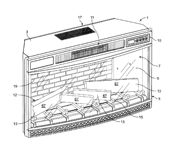
[0021] FIG. 1 illustrates an electric fireplace 1 in accordance with an
embodiment of
the present invention. The electric fireplace 1 may be a freestanding
component or it may
include an insert configured to be received within another structure, such as
a piece of furniture
(e.g., a piece of cabinetry) or an opening in a wall of a building, or even
within the firebox of a
traditional fireplace. The electric fireplace 1 includes a housing 3 defining
an interior volume.
The front 5 of the electric fireplace 1 includes a main opening 7. An at least
partially translucent
or transparent structure, such as a window pane 9 may be positioned in the
opening 7.
[0022] The electric fireplace 1 may include controls 10 for controlling
the operation of
the fireplace 1. Also, the electric fireplace 1 may also include another
opening with a grill 11
arranged above the main opening 7, to direct heat out of the electric
fireplace 1 to heat the area
located in proximity to the fireplace. In that way, the electric fireplace 1
may function as a
heater and may provide at least some of the heat provided by a wood or other
fuel-burning
fireplace. As shown in FIG. 1, the controls 10 and the grill 11 may both be
located on the front
of the fireplace 1, for example above the main opening 7.
[0023] Inside the interior volume of the electric fireplace 1 is a log
set 12, which may
include one or more logs 13 positioned on a grate 15. The logs 13 are
preferably artificial,
although they may be real wood logs, and the logs 13 may be structured so as
to mimic real
wood logs. Typical materials for the logs 13 include polymers, ceramic, metal,
glass and wood
(although other materials may also be used), and the logs 13 may be colored
(e.g., painted,
dyed, etc.) so that their exterior surfaces mimic the appearance and color of
real wood logs.
-4-
CA 2965906 2017-05-01
H8324262CA
[0024] As shown in FIG. 2, an ember bed 16 is preferably arranged below
the log set
12, which can create the appearance of glowing embers and/or burned ash in a
traditional, wood-
burning fireplace. The ember bed 16 may be constructed of polymer, ceramic,
metal, glass, or
other material, and may be colored so that its exterior surface appears as
real glowing embers
and/or burned ash. Behind the log set 12, at the rear 17 of the housing 3, is
a rear wall 19. The
rear wall 19 preferably has a solid (non-transparent) appearance and may
include a design for
visual interest, such as a design which creates the appearance of the inside
of a traditional
fireplace. For example, as shown in FIG. 1, the design may include a brick
pattern. Other
interior walls 20 may also include the same or different designs, as shown in
the embodiment
illustrated in FIG. 11B.
[0025] Turning to the cross-sectional view in FIG. 2, a heater 21 is
arranged near the
top 23 portion of the housing 3. The heater 21 may be a convection heater that
blows heated
air out of one or more openings in the electric fireplace 3, such as the grill
11 on the front 5
illustrated in FIG. 1. The heater 21 may include a fan, such as a centrifugal
fan or blower 25,
for moving air past one or more heating elements 27 to heat the air before it
exits the grill 11.
The heater 21 need not be a convection heater, however, and any other suitable
heater for
providing desired warmth to the area located in proximity to the fireplace may
be used, such as
a radiant heater.
[0026] Also inside the housing 3 of the electric fireplace 1, is a
lighting system that
simulates aspects of the illumination patterns observed in wood or other fuel-
burning fires. For
example, the lighting system may include a rear projector for projecting
lighting effects onto a
screen behind the log set 12. Alternatively, the rear wall 19 may function as
such a screen. The
rear projector may include a rear light source 29 and a rear spinner 31. As
shown in FIGS. 4-
5, the rear light source 29 may include an array of lights 33, such as LEDs,
supported by a
supporting structure 35 (such as a printed circuit board). Other types of
lights may be used
without limitation, however, including, for example, incandescent, fluorescent
and halogen
lights. The lights may be colored (or they may have multiple colors) in order
to mimic the
colors emitted by a real, fuel-burning fire. As also shown in FIGS. 4-5, the
rear spinner 31
includes a central axle 37 that is supported at least at one end by a support
39, but desirably has
-5-
CA 2965906 2017-05-01
H8324262CA
supports 39 at each end, and is rotationally driven about the axle 37 by a
motor 41. A plurality
of strips 43 of at least partially reflective material radiate outwardly from
the axle 37 along its
length. Those strips 43 may each extend outwardly from the axle 37 along a
variety of twisting
and/or undulating paths, and/or their peripheral edges may have a variety of
curving profiles.
[0027] As shown in FIG. 3, the rear light source 29 and rear spinner 31
are desirably
arranged so that light emanating from the rear light source 29 reflects at
least partially from the
strips 43 of the rear spinner 31 and is projected onto the rear screen 19,
which may be non-
transparent. By rotating the rear spinner 31 about its central axle 37, the
projected light on the
rear screen 19 will desirably move and/or flicker similarly to light emanating
from a real fuel-
burning fire. A flame-shaping template 45 may also be provided between the
rear spinner 31
and the rear screen 19 in order to shape the light projected onto the rear
screen 19. As shown
in FIG. 6, that template 45 may be a panel having flame-shaped cutouts 47 that
permit light to
pass through them.
[0028] The lighting system may also include a front projector for
projecting lighting
effects onto one or more of the logs 13 and/or the ember bed 16. The front
projector may
include a front light source 49 and a front spinner 51. As shown in FIGS. 4-5,
the front light
source 49, like the rear light source 29, may include an array of lights 53
(such as LEDs)
supported by a supporting structure 55 (such as a printed circuit board). As
with the rear light
source 29, other types of lights may be used in the front light source 49
without limitation,
including, for example, incandescent, fluorescent, and halogen lights. The
lights may also be
colored, and they may have multiple colors, in order to mimic the colors
emitted by a real, wood
or other fuel-burning fire. As also shown in FIGS. 4-5, the front spinner 51
includes a central
axle 57 that is supported at least at one end by a support 59, but desirably
has supports 59 at
each end, and is rotationally driven by a motor 61. The central axle 57
includes a plurality of
light-reflecting strips 63 of at least partially reflective material along its
length. Those strips 63
may have similar or identical shapes to those discussed above in connection
with the rear
spinner 31.
100291 In one embodiment, as shown in FIGS. 2-5, the front and rear
spinners have
similar structures, but the front spinner 51 has a smaller diameter (as
defined by the radial extent
-6-
CA 2965906 2017-05-01
H8324262CA
of the strips 63) than that of the rear spinner 31, and the central axle 57 of
the front spinner 51
may be positioned closer to the bottom 65 of the fireplace housing 3 than that
of the rear spinner
31. As shown in FIG. 3, the front light source 49 and front spinner 51 are
desirably arranged
so that light emanating from the front light source 49 reflects at least
partially off of the strips
63 of the front spinner 51 and is projected onto the logs 13 and/or ember bed
16. By rotating
the front spinner 51 about its central axle 57, the projected light on the
logs 13 and/or ember
bed 16 will desirably move and/or flicker similarly to light created by a wood-
burning fire.
[0030] A
log set 12 in accordance with preferred embodiments of the present invention
desirably includes a plurality of logs 13, such as four logs shown in FIG. 1.
Desirably, at least
one of those logs 13 includes at least one substantially planar face 67
extending along its
longitudinal axis such that the log 13 mimics a natural log which has been
split in the
longitudinal direction. Preferably, the log 13 is oriented such that the
substantially planar face
67 faces in a generally forwards direction towards the front 5 of the
fireplace 1. In that way,
desirably the planar face 67 acts somewhat like a projection screen that it is
better adapted to
receive the light projected from the front spinner 51 than the more curved
surfaces 69 of the
other portions of the log 13. The substantially planar face 67 of the log 13
would preferably
not define a completely flat plane, but rather would extend generally along a
plane, particularly
in comparison to the more curved surfaces 69 of the other portions of the log
13. Indeed, like
natural logs that have been split along their longitudinal dimensions, the
substantially planer
face 67 would preferably at least have linear ridges extending in the
longitudinal direction,
similar to the longitudinal fibers of a natural split log. Moreover, the
surface 67 would also
preferably deviate at least slightly from the plane along which it extends at
one or more
locations, so as to resemble the imperfections of a natural split log face.
Furthermore, to better
resemble a natural split log, the log 13 is desirably colored (e.g., painted,
dyed, etc.) differently
in different locations. For example, the substantially planar face 67 may
include a different
color than the color of the more curved surfaces 69. In that way, the log 13
may mimic the
natural color differences in natural logs, which often have outer, curved
surfaces that are
covered with bark having a different color than the color of the interior of
the log that is exposed
when the log is split. For some logs, the interior is a lighter color than the
color of the bark.
-7-
CA 2965906 2017-05-01
H8324262CA
For other logs, such as those from birch trees, a split log may include an
interior with a beige
tone while the exterior curved surface is covered with a white bark.
Regardless of the color
difference, the planar face 67 of the log 13 may function better as a
projection screen for the
light projected from the front spinner 51 than the more curved surfaces 69 of
the other portions
of the log 13. In some instances, logs that have a lighter color on the
substantially planar face
67 may more effectively display the light projected onto it by the front
spinner 51.
[0031] Desirably, the logs 13 of the log set 12 in accordance with
preferred
embodiments of the present invention extend at different angles to one
another. For example,
as shown in the embodiment of the log set 12 illustrated in FIG. 1, as well as
the embodiment
of the log set illustrated in FIGS. 9-10, the logs 13 extend along
longitudinal axes that are
transverse to one another. Alternatively, or additionally, the logs 13 may be
generally arranged
in multiple rows. For example, as shown in the embodiment of FIGS. 9-10, the
log set 12 may
include two logs 13 in a first row 71 which is positioned more towards the
front 5 of the fireplace
1 (e.g., closer to transparent pane 9) than the logs 13 in a second row 73.
Desirably at least one
log in each row may be a split log having a substantially planar face 67, with
the face 67 facing
in a generally forwards direction towards the front 5 of the fireplace 1, as
discussed above. For
example, all of the logs 13 in the log set 12 may have such forwardly facing
substantially planar
faces 67. The logs 13 in one or more rows may also be transverse to other logs
13 in the same
row. For example, as shown in FIGS. 9-10, the two logs 13 in the first row 71
are oriented so
that their substantially planar faces 67 angle slightly towards one another.
Similarly, the two
logs 13 in the second row 73 are oriented so that their forward-facing planar
faces 67 are also
angled slightly towards one another.
[0032] Desirably, the above-discussed features of the preferred
embodiments of the
invention, and particularly combinations of multiple such features, give the
log set 12 and the
simulated fire a more natural, three-dimensional appearance. In that regard,
having a log set 12
in which at least one of the logs 13 has a forwardly-facing, substantially
planar face 67 for
receiving flame-mimicking light projected from the front projector,
particularly in combination
with a non-transparent rear wall 19 or screen behind the logs 13 that receives
flame-mimicking
light projected from the rear projector, desirably provides a realistic three-
dimensional flame
-8-
CA 2965906 2017-05-01
H8324262CA
effect in conjunction with a log set having a natural, split-log appearance.
Moreover, providing
an arrangement of a plurality of logs 13 in the log set 12 that extend in
different, transverse
orientations, and also are positioned in front of or behind one another, will
add to the three-
dimensional flame effect when the front projector projects flame-mimicking
light on multiple
ones of those differently positioned logs 13.
[0033] To further add to the lighting effects and increase the realism of
the simulation,
one or more of the logs 13 in the log set 12 may be at least somewhat
translucent and may
include one or more internal lights such that the log(s) 13 appear to glow.
The ember bed 16
may similarly be at least somewhat translucent, and one or more lights may be
included below
the ember bed 16 such that it appears to glow as in the case of a real wood
fire.
[0034] Various steps in the assembly of one embodiment of the present
invention are
illustrated in FIGS. 4-10. For example, a baseplate 75 to be positioned at the
bottom 65 of the
housing 3 may first be assembled with the rear light source 29, rear spinner
31, front light source
49, and front spinner components 51, as shown in FIGS. 4-5. Then, a flame-
shaping template
45 may be provided to the rear of the rear spinner 31, as shown in FIG. 6. A
panel 77 may then
be provided between the rear spinner 31 and the front light source 49, which
panel 77 may be
attached along its top end 79 to the top 81 of the flame-shaping template 45,
as shown in FIG.
7. In that way, the panel 77 and flame-shaping template 45 may define an
enclosure 78 around
the rear light source 29 and rear spinner 31, as shown in FIG. 3. In order to
reduce errant
reflections and/or prevent the light of the rear light source 29 from escaping
towards the front
of the fireplace 1 past the panel 77, the panel 77 is desirably dark colored,
non-reflective,
and/or does not transmit light through it. A preferred material for the panel
77 may be rubber.
After the panel 77 is secured, the ember bed 16 may be positioned over the
panel 77, as shown
in FIG. 8. The log set 12 may then be positioned on top of the ember bed 16
and the enclosure
78, as shown in FIGS. 9-10. The baseplate 75 with the above-discussed
components attached
to it may then be positioned within the housing 3 of the electric fireplace 1.
[0035] In operation, the rear projector may be operated to project flame
shaped light 81
on the rear screen 19, as shown in the illustrations of FIGS. 12A-B, and that
light 81 may flicker
and/or move, for example based on the rotation of the rear spinner 31, as
discussed above. As
-9-
= CA 2965906 2017-05-01
H8324262CA
shown in FIG. 11, the reflected light from the illuminated strips 43 of the
rear spinner 31 may
pass through the flame-shaping template 45 before being projected on the rear
screen 19. As
also shown in FIGS. 12A-B, light 83 may be projected onto the substantially
planar surfaces 67
of the logs 13 in the log set 12, which light 83 may also flicker and/or move,
as discussed above,
in order to simulate a real wood-burning fire.
100361 In accordance with other embodiments of the invention, the
lighting system may
include multiple front projectors. Some such embodiments may include multiple
rows of front
projectors, for example with each row corresponding to a respective row of
logs. That is, each
row of front projectors can be positioned such that the light from the
projector (e.g., the reflected
light from the spinner) is directed onto its own associated row of logs. Such
embodiments may
provide added depth to the flame simulation. In other such embodiments,
multiple front
projectors may be provided with at least one being associated with its own
log. For example,
particularly where multiple logs within a particular row are significantly
angled with respect to
one another, multiple front projectors may be provided where each projector is
associated with
its own log, so as to provide optimal lighting projection onto each log. Each
such projector
may, for example, be aligned with the respective log, such that the spinner
and the light source
extend substantially parallel to the longitudinal axis of the associated log.
[0037] In accordance with yet further embodiments of the
invention, multiple lighting
projectors may be coordinated, e.g., such that it looks like a flame starts on
one of the logs and
then continues up onto the rear screen. For example, a rotation control system
may synchronize
the rotation of the front spinner 51 and rear spinner 31 so as to create that
or other lighting
effects. One example of such a rotation control system may include a physical
interconnection
(e.g., a chain or belt drive) between the front spinner 51 and the rear
spinner 31. In such an
example, a pulley on each axle 37, 57 of the rear and front spinners 31, 51,
respectively, may
be interconnected with a belt, or a sprocket on each axle of the front and
rear spinners may be
interconnected with a chain, so that both axles rotate together. In such an
embodiment, one of
the front or rear motors 41, 61 may be eliminated, such that both spinners 31,
51 are controlled
by a single motor via the interconnecting belt or chain. Alternatively, both
front and rear motors
41, 61 may be eliminated, and a single motor may be provided that drives the
interconnecting
-10-
CA 2965906 2017-05-01
. ,
H8324262CA
belt or chain directly, so as to induce synchronized rotation of both spinners
31, 51. Another
example of a rotation control system may include electronic control of the
rotation of the front
and rear spinners 51, 31. For example, the control system that controls each
motor 41, 61 may
be programmed to synchronize the rotation of both spinners. In such an
example, the motors
may be stepper motors or servomotors, so that their rotation can be precisely
controlled.
Alternatively, or additionally, the axles 37, 57 and/or the motors 41, 61 may
include rotary
encoders, so that their rotational position can be monitored and controlled by
the control system.
[0038] Although the invention herein has been described with
reference to particular
embodiments, it is to be understood that these embodiments are merely
illustrative of the
principles and applications of the present invention. It is therefore to be
understood that
numerous modifications may be made to the illustrative embodiments and that
other
arrangements may be devised without departing from the spirit and scope of the
present
invention as defined by the appended claims.
-11-