Note: Descriptions are shown in the official language in which they were submitted.
CA 02966062 2017-04-27
Device for Introducing a Medium into a Container
The present invention is directed to an apparatus for passing a medium into a
container
according to the preamble of claim 1 and a corresponding method according to
the preamble of
claim 15.
Prior art
Apparatuses for passing a medium into a container are especially known in the
beverage
processing industry.
In order to achieve this, usually machines are used that, for example, are
embodied as rotary
machines and that can comprise a carousel in which the not yet filled
containers are introduced
into a filling station and are filled in the same. For this purpose, filling
vents are positioned either
over the container or moved into the same. A filling of the containers with
the medium is made
through these filling vents. The medium is, for example, the product to be
filled into the
container.
When filling the product, specific requirements are provided for the
cleanliness around and in the
opening of the container that can only be fulfilled with high effort.
Objective
Starting from the prior art, it is an object of the invention to provide an
apparatus for passing a
medium into a container that allows for a passing of the medium into a
container in a preferably
contamination-free manner.
Solution
This object is solved according to the invention by the apparatus according to
claim 1 and the
method according to claim 15. Advantageous embodiments of the invention are
provided in the
dependent claims.
The apparatus for passing a medium into a container, for example, a flexible
pouch, according to
the invention is characterized in that an indirect magnetic drive means for
moving the lance is
provided, wherein a first part (lance part) of the magnetic drive means is
joined with the lance
and a second part (drive part) of the magnetic drive means is indirectly
magnetically coupled
with the lance part. Here, according to the invention, the term "indirect
magnetic drive means" is
1
1 CA 02966062 2017-04-27
to be understood as a drive means for which only the drive part is driven or
actively moved and
this movement is transmitted to the lance part due to magnetic or
electromagnetic interaction of
the drive part with a lance part. Therein, it is provided that the lance part
and the drive part are
separated spatial from another and, in particular, no contact of these parts
occurs such that the
transmission of the movement of the drive part to the lance part is
exclusively made by the
magnetic or electromagnetic interaction of those parts among each other.
The apparatus according to the invention allows in particular for a passing of
a medium (in
particular a gaseous medium for sterilizing) in an area separated from the
environment since the
movement of the lance part can also be made without a mechanical connection
with the drive
part. By this, particular conditions with respect to the asepsis or sterility
or cleanliness in the area
of the opening of the container can be realized. Furthermore, the use of
lubricant in the area of
the lance can be foregone.
In one embodiment, the lance and the lance part are arranged in a tube and are
moveable along
the longitudinal axis of the tube and the drive part is arranged outside the
tube and moveable
along the longitudinal axis of the tube. This tube can enclose the opening of
the container and
can thus create a surrounding area in which the medium is passed into the
container that is at
least partially isolated from the environment.
In a further development of this embodiment, the apparatus is characterized in
that the drive part
is connected with a drive, wherein the drive part is moved along the tube by
means of the drive.
The movement of the drive part can thus be translated into a movement of the
lance part
together with a lance inside the tube.
Furthermore, it can be provided that the drive comprises an arm moveably
connected with the
drive part, wherein the arm is moveably arranged along a control cam via a cam
roll and the
movement of the cam roll along the control cam is translated into a movement
of the drive part
along the tube. This embodiment is particularly maintenance-free and works
without additional
drive motors such that malfunctions can be avoided.
In an advantageous further development, the apparatus is characterized in that
the control cam
is stationary arranged at the carousel. The rotational movement of the
carousel relative to the
guide can thus be translated into a movement of the arm such that control
units for the
movement of single arms of the treatment stations can be omitted.
2
N
(.. CA 02966062 2017-04-27
=
1
In a further embodiment, the arm is connected with a spring element that
pretentions the arm in
an initial position. By this, for example the resetting of the arm into the
initial position can be
made easier.
In one embodiment of the apparatus according to the invention, the drive part
is embodied as a
magnet encompassing the lance part. This embodiment allows an indirect drive
of the lance part
independent of how the lance part is oriented, in particular twisted relative
to the drive part.
It is advantageous if the lance part is arranged at one end of the lance and a
nozzle is arranged
at the other end of the lance, wherein the medium is led from a reservoir
through the lance to the
nozzle. Contaminations of the lance part due to in particular a fluid medium
leaking out from the
nozzle can thus be prevented.
Furthermore, it can be provided that the medium is a sterilizing gas and/or
the medium is the
product to be filed into the container. The invention can thus be applied to
the cleaning of the
container and the filling of the container.
In a further development of the previous embodiment, the control cam
encompasses the
rotational axis of the carousel and the shape of the guide is continuous.
According to a further embodiment of the apparatus, it is provided that the
drive means
comprises a linear drive or a servo drive. This alternative embodiment allows
for a selective
control of the movement of the drive part of the magnetic drive means in each
treatment station.
In an advantageous embodiment, the invention is characterized in that the
lance can be rotated
by means of the drive means. The rotation can in particular be advantageous
when cleaning the
container since, thereby, the introduced cleaning medium can be distributed
better.
In a preferred further development of this embodiment, the lance part is
arranged on a guide
within the tube, wherein the guide is adapted to cause a rotation of the first
lance part relative to
the tube while the movement of the lance part along the longitudinal access of
the tube.
Thereby, the rotation of the lance can be achieved without additional drive
means solely by the
magnetic interaction of the first part and the drive part among each other and
the movement of
the lance part along the tube preset by the guide.
3
L. 1 CA 02966062 2017-04-27
,
%
Furthermore, the device can be characterized in that the lance part is mounted
on the guide by
means of a lubricant-free bearing, in particular a four-point contact bearing.
Undesired
contaminations inside of the tube can thus be avoided.
The method according to the invention for introducing a medium into a
container, for example a
flexible pouch, comprises introducing the medium with a lance and is
characterized in that the
lance is indirectly magnetically moved into the container in order to
introduce the medium.
In one embodiment, a sterilizing gas or a product is passed into the container
via the lance.
It can be provided that the lance is moved along a longitudinal axis of a tube
and is introduced
into the container for passing the medium and is subsequently pulled out.
In a further development of this embodiment, it is provided that the lance is
rotated during the
passing. This embodiment of the method according to the invention allows, in
particular when
passing a cleaning medium, a reliable distribution of the medium inside the
container.
Brief description of the drawings
Figure 1 schematic depiction of an apparatus according to the invention
Figure 2 schematic depiction of a treatment station
Figure 3a perspective view of a treatment station according to one
embodiment
Figure 3b enlarged view of the head area of the treatment station
according to Figure 3a
Figure 4a side view of the treatment station with a lance moved into a
container
Figure 4b top view of the treatment station of Figure 4a
Figure 4c side view of the treatment station with a lance pulled out
from a container
Figure 4d top view of the treatment station of Figure 4c
Figure 4e schematic depiction of the position of the treatment stations
of Figure 4a and
Figure 4c in relation to a control cam
Figure 5a schematic top view of a tube of a treatment station according
to one embodiment
in which the lance is rotatable
4
CA 02966062 2017-04-27
Figure 5b perspective view of the embodiment with a rotational drive for
the lance
Detailed description
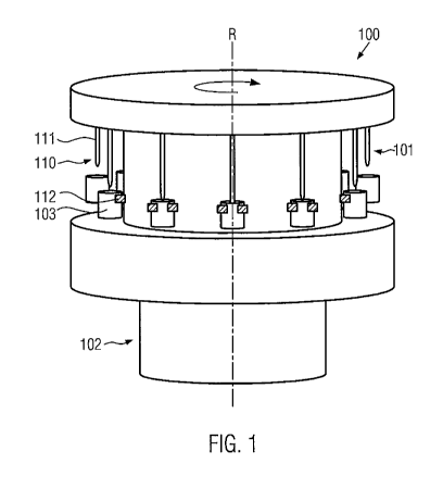
Figure 1 shows an apparatus 100 according to the invention that is adapted for
passing a
medium into a container, in particular a flexible container like a pouch 103.
For this purpose, the
apparatus comprises a carousel 101 rotary mounted on a frame 102 with a
plurality of treatment
stations 110. While the embodiment as rotatable carousel (rotational axis R)
is preferred, of
course other embodiments can be thought of in which a linear apparatus is
provided which does
not rotate (linear filler or the like), and in which the containers are filled
in separate stations..
The containers can, for example, be fixed on holders 112 in the apparatus 110
that are
embodied in the form of clamps and attached to the sides of the container or
pouch,
respectively.
According to the invention, lances 111 can then be introduced into the
containers 103 and a
medium can be introduced via the same. This is schematically depicted by the
position of the
lance at different positions of the machine in relation to the rotational
direction. The lance
depicted in the middle is inserted into the container, the lances to the right
of the middle are not
yet inserted into the container and the lances to the left of the middle are
pulled out of the
containers again in this depiction. The lances 111 do not necessarily need to
be inserted into the
container 103. It is sufficient when the lances 111 and a corresponding outlet
opening for the
medium are positioned over the opening of the container 103.
It is provided according to the invention that the lances 111 can be moved
into the direction of
the containers or pouches 103, respectively, or can be moved away from the
same, wherein the
drive of the lances 111 takes place via an indirect magnetic drive means not
yet depicted in
detail in Figure 1. Therein, "indirect" means, according to the invention,
that a driving force of, for
example, a motor or the like is not directly translated into a movement of the
lance, but rather an
indirect translation via at least one magnetic or electromagnetic interaction
is provided such that
a first part of the indirect magnetic drive means, that is joined with the
lance (in the following also
referred to as lance part) can be moved by means of a second part (drive part)
of the magnetic
drive means that, in turn, is driven. Herein, the lance part and the drive
part of the indirect
magnetic drive means are connected indirectly only via magnetic or
electromagnetic interactions
1
L CA 02966062 2017-04-27
v
among each other. A mechanical connection or a mechanical contact of the first
and the drive
part is preferably not provided.
For this, Figure 2 shows a schematic view of a treatment station for
illustrating the basic principle
of the indirect magnetic drive means.
In Figure 2 a treatment station 110 is depicted. It comprises a tube 220 that
is depicted in cross
section. The lance 221 extends through the inner space of the tube 220.
The lance 221 is joined with the lance part 223 of the indirect magnetic drive
means, for example
via screwing. The lance part 223 is movable inside the tube wherein at least a
movement along
the longitudinal axis, i.e. into the container and out of the container 103,
is possible.
Furthermore, a medium supply 224 is depicted in which the medium to be
introduced into the
container is provided, in particular a gaseous cleaning or sterilizing medium.
The lance as a
component extends only into the area of the lance part 223 and ends at the
upper end of the
lance part. Here, the lance can be open to the top, i.e. in the direction of
the medium supply, or a
valve can be provided.
The space in tube 220 above the lance part can be filled at least partially
with the medium to be
filled into the container in case the lance is moved into the container such
that the medium can
be guided from this area through the lance into the container. For this
purpose, opening the
medium supply for letting in the medium in the area of the tube can be
controlled depending on
the position of the lance such that the medium is let in before the lance is
inserted into the
container.
The lance part 223 is indirectly magnetically coupled with the drive 222 of
the indirect magnetic
drive means. The drive part 222 is arranged outside the tube 220 and movable
along the tube.
The drive part 222 is moved by means of a drive 241 which is only shown dashed
here. Due to
the indirect magnetic coupling of the lance part 223 with the drive part 222,
a movement of the
drive part 222 is translated into a movement of the lance part 223.
Figure 3a shows a more detailed view of a preferred embodiment of the
invention according to
the principle of Figure 2.
In this embodiment, the lance 221 is arranged together with the lance part 221
of the indirect
magnetic drive means in the tube 220, for passing the medium into the
container or pouch 103,
6
1
',.. CA 02966062 2017-04-27
,
respectively. The lance 221 is joined with the lance part 223 of the indirect
magnetic drive
means, wherein the lance part is movably mounted together with the lance 221
inside the tube
220.
At the lower end of the tube 220, an opening area 266 can be provided into
which the opening of
the container 103 can be inserted. The opening area 266 can also completely
encompass the
opening of the container 103 such that an isolation of the opening area of the
container 103 from
the surrounding atmosphere takes place. Thus, the filling of the medium can
happen under
preferably aseptic conditions.
Outside the tube 220, the drive part 222 of the indirect magnetic drive means
is arranged. This
part is also movable along the tube 220. For this, the drive part 222 can for
example be mounted
on a guide at the outer side of the tube 220. Due to the use of a
corresponding guide, a correct
upward and downward movement of the drive part along the tube can be ensured.
Here,
particularly low friction kinds of guides like, for example, a guide rail and
a four-point contact
bearing mounted therein can be used.
This, however, is not necessarily the case. The drive part 222 can also be
arranged with a small
distance, for example 0.5 mm or 1.0 mm or 2.0 mm from the outside 220 of the
tube and can be
movable along the longitudinal axis of the tube.
Here, the drive part 222 can, for example, partially or completely encompass
the tube 220 as a
hollow cylinder. In a corresponding embodiment, the drive part 222 completely
extends around
the depicted tube 220. The drive part can, however, also be comprised of
single elements, for
example cuboid-shaped, that are evenly distributed over the circumference of
the tube 220 or
can be arranged at specific, possibly also unevenly distributed positions.
In order to move the lance 221 inside the tube 220, it is provided that the
drive part 222 is
connected with a drive 241 that moves the drive part 222 along the
longitudinal axis of the tube
220. The drive 241 depicted in Figure 3a is, on its own, movable. The movement
of the drive 241
can be translated into a movement of the drive part 222.
By the movement of the drive part 222, indirectly also the lance part is moved
due to the
magnetic or electromagnetic interaction between the lance part and the drive
part, such that the
lance 221 is moved into the container 103 or out of the container 103.
7
CA 02966062 2017-04-27
Here it is provided according to the embodiment depicted in Figure 3a, that
the drive part 222 is
connected with an arm 226 of the drive 241. The arm can be connected via a
movable
connection with the drive part 222 or be hinged at the same, respectively.
For this purpose, it can be provided that the arm 226, at least in the area in
which it is hinged at
the drive part 222, is embodied as a double rocker 246. This way, it can
clutch with two sides at
the drive part 222. On each side, corresponding bearings 245 can be provided
which connect
the area of the double rocker 246 with the drive part 222. The connection with
the drive part 222
can, here, for example happen indirectly via the sleeve 247 in which also the
bearing 245 can be
arranged. This form of the connection of the arm 226 with the drive part 222
is particularly stable
and prevents potential misalignments during the movement of the drive part.
The arm 226 can additionally be connected with a guiding arm 227, wherein the
guiding arm 227
is hinged at a point 228. The guiding arm 227 is rotatably mounted around the
point 228. Also,
the guiding arm 227 can be embodied as double rocker at both the hinge point
at arm 226 and
hinge point 228. The hinge point 228 can, for example, be arranged at the tube
220. Also, in the
hinge point 228, a corresponding bearing for rotatably mounting the guiding
arm 227 can be
provided. A movement of the arm 226 can, thus, be stabilized and/or guided by
the guiding arm
227.
The guiding arm 227 can be connected with the arm 226 either in a further
hinge point or can be
movably mounted along a guide provided in the arm 226. The hinging of the
guiding arm 227 in
point 228 defines a certain scope for the arm 226.
Further, it is provided in the embodiment according to Figure 3a that the arm
226 is arranged on
a carriage 280 that is movably mounted along a support pole 229. It can also
be provided that
the arm 226 is embodied together with the carriage 280 as a double rocker in
the area of the
connection. This connection provides for high stability.
The support pole (support arm) 229 can be connected with the tube 220 and the
complete
treatment station can be fixed to the carousel. For this purpose, for example
a screwing 232 can
be provided. The fixing can additionally be provided by further means for
fastening. The arm 226
can be arranged on the carriage 280 for example by means of a spherical joint
like it is also
depicted in Figure 3a with reference sign 243. On the carriage 280, further
cam roll 230 can be
arranged.
8
t CA 02966062 2017-04-27
The cam roll can, for example, be rotatably mounted on a carrier or pin. This
pin can be rigidly
connected with the carriage 280. The movement of the carriage along the pole
can be limited in
at least one direction by means of stop 264.
This cam roll can revolve along a control cam that is stationary arranged with
respect to the
carousel. In order to ensure for the contact of the cam roll 230 with the
control cam, a spring
element 225 can be connected with the carriage, wherein the spring element 225
can pretension
the carriage and thus the cam roll 230 against the corresponding control cam.
The spring
element 225 can be arranged around the support pole 229. A possible embodiment
of the
control cam is depicted in the schematic top view according to Figure 4e.
The use of the stop 264 can be used in an advantageous manner here in order to
specify the
maximum penetration depth of the lance into the container. Since the spring
element 225
pretensions the carriage in a position in which the lance is inserted into the
container, wherein
the spring element 225 presses the carriage in the direction of the stop 264,
the movement of
the carriage 280 can be limited at a specific position by the choice of the
dimensions of the stop
264 in the direction of the movement of the carriage 280, such that a further
moving of the
carriage beyond this position (i.e. beyond the stop) is made impossible,
whereby a further
movement of the lance into the container can be prevented. Consequently, the
maximum
penetration depth of the lance into the container can be specified also
independent from the
control cam. The control cam can thus comprise a gap in an area in which the
lance is moved
into the container for passing the medium or can be distant further away from
the carriage 280 or
the cam roll 230, respectively, than the stop 264, such that the carriage
together with the cam
roll runs against the stop.
While the spring element 225 is connected, on the one side, with the carriage
280, it can be
provided that the other side of the spring element 225 is either connected
with the support pole
229 or with the tube 220.
Due to a suitable choice of the control cam, that can be arranged, for
example, around the
rotational axis R or the carousel depicted in Figures 1 and 4e, the movement
profile of the drive
part 222 and, thus, the movement profile of the lance 221, can be pre-set
without requiring
complicated control means.
In order to avoid jerky movements of the lance 221, it is particularly
advantageous if the control
cam 231 has a shape that can be at least piece-wisely described by
mathematical functions that
9
CA 02966062 2017-04-27
are continuous in each point. It is particularly preferred if the functions
describing the control cam
231 are also continuous with their first derivation.
Furthermore, a medium supply 224 can be associated with the tube 220. In the
medium supply,
the medium to be inserted, particularly a sterilizing gas, can be stored. The
medium can fill the
space within the tube until the lance part and can flow into the lance through
an opening of the
lance at the upper side of the lance part that faces the medium supply, by,
for example, applying
a higher pressure to the medium in the tube compared to the pressure of the
environment.
Figure 3b shows the head area of the treatment station according to the
embodiment of Figure
3a with the medium supply 224 in a detailed depiction, wherein the drive part
222 and the lance
part 223 together with the lance 221 are also displaced into this area of the
tube 220. In the
medium supply 224 a hollow space, in particular a pipe line, can be provided
through which the
medium that is to be filled into the lance 221 can be channeled. The
channeling of the medium
can, for example, happen through the depicted valve 274.
In one embodiment, it can be provided that, during each upward movement of the
lance, the
medium that is to be passed into the container is channeled through the valve
into the lance by
opening the valve 274 in the area of the medium supply 224. If the lance is
again moved away
from the medium supply 224 into the direction of the container, the valve can
be closed and the
supply of medium via the medium supply 224 can be interrupted. According to
this embodiment,
the lance would thus transport the medium that is to be introduced into the
container from the
medium supply 224 to the container, wherein the lance 221 would not be
permanently
connected with the medium supply.
Furthermore, figure 3b shows a more detailed view of the drive part 222 and
the lance part 223.
The connection described with reference to figure 3a between the drive, in
particular the arm
226, and the drive part 222 is depicted here in more detail. When the arm 226
is embodied as
double rocker, each part of the double rocker engages on the left side or the
right side,
respectively, at the drive part 222. Here, it is connected via, for example,
screwings or bolts 245
with the drive part 222. The mounting of the double rocker at the drive part
222 is preferably
moveable, in particular rotatable. Thus, it can be ensured that, during
movement of the arm 226,
the drive part 222 can be moved along the tube.
Additionally, it is depicted in figure 3b that the drive part 222 is
surrounded by a hull 263. In
particular, the drive part can be encapsulated on all sides facing away from
the tube 220 by the
I CA 02966062 2017-04-27
hull. Contaminations of the drive part can thus be prevented. Furthermore, the
hull can be
comprised of diamagnetic material in order to localize the magnetic fields of
the drive part 222
and the lance part 223 preferably in the area of the tube.
The embodiment of the indirect magnetic drive part according to figure 3a and
3b is not
mandatory. It can also be provided that the drive part is moveable along the
tube 220 along the
direction of arrow depicted via a servo drive. It can also be provided that
the drive part 222
together with the lance part 223 forms a linear drive, wherein the drive part
222 can be
embodied as a plurality of electromagnets that are stationary mounted outside
of the tube 220.
By actuating the separate electromagnets, a movement of the lance part 223
together with the
lance 221 can be realized.
For each treatment station 110, a separate control unit can be provided in
this case, that
actuates the electromagnets such that, in each treatment station 110, a
possibly individual
movement profile of the lance part 223 together with the lance 221 can be
achieved. This is
particularly of advantage in case different containers that, for example, vary
in their size, are
treated in the apparatus according to figure 1 during one treatment cycle.
The lance part is comprised of or comprises a permanent magnet. The drive part
can also
comprise a permanent magnet, but can also be embodied as electromagnet or
comprise the
same.
In principle, the medium used can, for example, be a gaseous medium like
hydrogen peroxide
(H202) for sterilizing the inner area of the container 103 or it can be the
product to be filled into
the container 103. However, also other gaseous media can be used for
sterilizing. Furthermore,
an inflating of the pouch by means of introduced air can happen.
Alternatively, the apparatus can
also be used to fill a product to be filled into the container/pouch.
Particularly when using a gaseous medium, it can be provided that the tube 220
extends at least
around the opening area of the container 103 arranged in the treatment station
110.
Furthermore, it can be provided that, by a corresponding outlet opening of the
lance or by an air
or medium supply within the tube 220, an at least slight overpressure is
applied in the area of the
opening of the container 103 compared to the pressure outside the treatment
station, such that
no air from the outside enters into the opening area of the container 103.
Thereby, the
introducing of the medium via the lance 220 can happen at preferably aseptic
conditions. This
11
,
= CA 02966062 2017-04-27
,
embodiment can advantageously be used to realize filling of the product into
the container 103
by a corresponding treatment station 110 under preferably aseptic conditions.
Figure 4a shows a treatment station corresponding to the embodiment according
to figure 3 with
a lance moved into the container. Figure 4b is a top view onto the treatment
station of figure 4a.
Furthermore, figure 4c shows the treatment station with a lance moved out of
the container and
figure 4d shows a corresponding top view onto the treatment station. In figure
4e, a schematic
top view of the carousel with a control cam is depicted for illustrating the
movement sequence.
In the arrangement 250 in figure 4a, the lance 221 is moved into the container
102 and
introduces or has introduced the medium. The carriage 280 is, in this state,
situated close to the
stop 264 wherein the cam roll is either in contact with the control cam 231 or
is not in contact
with the same and is pressed against the control cam 231 or the stop by the
spring element.
This is synonymous to the distance of the control cam 231 to the rotational
axis R of the
carousel according to figure 1 being smallest (also refer to figure 4e).
After the medium has been passed into the container 103, the lance is now
piecewise or
continuously pulled out from the container 103. In order that the lance 221
can be backed out
from the container 103, the lance part 223 must be moved away from the
container 103 along
the tube 220. Correspondingly, also the drive part 222 has to be moved away
from the container.
In order to achieve this, the arm 226 must be moved towards the tube 226. This
is achieved by
the cam roll being moved away from the rotational axis R of the carousel by
the control cam
against the tension of the spring element. In the situation 250' depicted
figure 4c, the distance of
the control cam 231 to the rotational axis R of the carousel is thus bigger
than the distance in the
situation depicted in figure 4a.
As is recognizable from figure 4c, the carriage was likewise moved away from
the stop 264
(along the pole), such that the arm 226 was rotated around the hinge 243 (for
example a
spherical joint) and was displaced into the depicted erected position.
Correspondingly, a
movement of the drive part 222 took place such that the lance part is
indirectly driven and the
lance is moved away from the container.
In figure 4c, the lance 221 arrived at the endpoint of the movement furthest
outside the container
103.
The corresponding distances of the control cam to the rotational axis in
position 250 according to
figure 4a and 250' according to figure 4c are schematically depicted in figure
4e.
12
CA 02966062 2017-04-27
During movement of the lance 221 out of the container 103, in particular when
using this
apparatus for passing a cleaning medium like hydrogen peroxide via an outlet
opening in the
lance 221 at the lower end (the end that is also moved into the container
223), bringing out of a
medium can be continued such that also the opening area of the container does
not come into
contact initially with the normal surrounding air.
Figure 5 shows a further embodiment of the indirect magnetic drive means. For
this, a cross-
section through the tube as it is depicted schematically in figure 2 is
provided in figure 5a. While
in the embodiment according to figure 2 and the embodiment as it was described
in figure 3a to
3b, the tube 220 can have an arbitrary cross-section, that can, for example,
be cornered or
round, a round inner cross-section of the tube 220 is envisaged in the
embodiment according to
figure 5. Inside the tube, the lance part 223 of the indirect magnetic drive
means for the lance
221 is arranged. The lance part 223 is depicted here as hollow cylinder that
is fixedly joined with
the lance 221 via connecting elements 460. The lance part 223 is not
necessarily provided as
hollow cylinder and can also be assembled from separate elements. For example,
one or more
cuboid-shaped elements can be provided that are arranged in the tube 220,
along a guide.
These are then each joined with the lance 221 via connecting elements 460.
According to the
embodiment in figure 5, the drive part 222 of the indirect magnetic drive
element in figure 5a is
also arranged as a hollow cylinder completely surrounding the tube 220. In the
embodiment
according to figure 5, it is necessary that the drive part 222 completely
surrounds the tube 220.
Admittedly, the outer cross-section of the tube 220 and the inner cross-
section of the drive part
222 do not need to be round as depicted, but in this way, cants can be
avoided.
Figure 5b shows a schematic view of the inner area of the tube 220, wherein
the tube 220 and
the drive part 222 of the indirect magnetic drive means are here depicted only
dashed and
translucent in order to not risk the clearness. In figure 5b, the lance part
223 is depicted
schematically by means of two cuboids. In the embodiment according to figure
5e, the lance part
223 is connected with a guide 450 being arranged inside the tube 220 via
guiding elements 451.
This can be provided as helix. By providing this guide and guiding the lance
part 223 by means
of the guiding elements 451 during a movement along the shown double arrow, a
rotation of the
lance 221 can be ensured. Due to the upward and downward movement of the drive
part 222
outside the tube 220, a rotational movement of the lance part corresponding to
the form of the
guide 450 can be superimposed to the upward and downward movement of the lance
part 223
inside the tube 220.
13
CA 02966062 2017-04-27
=
Here, the guide 450 does not need to be provided as a helix but can, for
example, also comprise
linear sections and differently strong curved sections. This embodiment is in
particular
advantageous during a cleaning of the containers with a cleaning medium since
the lance and in
particular one or the outlet openings that are moved into the container can be
rotated. If, for
example, a plurality of outlet openings are arranged at the circumference of
the lance, these can
treat the inner surface of the container under different exit angles of the
medium due to the
rotation. With this, it can be ensured that the cleaning is preferably
complete and effective since
in particular for flexible pouches, for example, folds can be treated under
different angles with
the cleaning medium.
Since the rotation of the lance or the outlet openings for the medium,
respectively, may only be
desired inside the container, it can be provided that during the movement of
the lance towards
the container, the guide 450 comprises a linear section that is in parallel to
the longitudinal axis
of the tube 220 and comprises a shape corresponding to a screw thread (helix)
only in the area
in which the lance part 223 is to be rotated in order to also allow for a
rotation of the lance while
this is at least partially introduced into the container.
The guiding elements 451 depicted in figure 5b are preferably lubricant-free
in order to prevent a
contamination of the opening area and in particular the inner area of the
container. For this, for
example, four-point ball bearings can be used.
While the above embodiments are all described by utilization of a tube in
which the lance and
the lance part are arranged, the tube can also be omitted and, instead of the
tube, only a guide
for the lance part of the indirect magnetic drive means can be provided such
that by moving the
drive part with the help of one of the above described drives, an indirect
drive of the lance part
and the lance joined thereto can be realized.
Since the lance part together with the lance are only indirectly connected
with the drive part of
the indirect magnetic drive means, there is the risk that that the lance part
together with the
lance falls down due to the gravity acting upon it. In order to prevent this,
the lance part can be
pretensioned by a spring element that, for example, is arranged inside the
tube in analogy to the
drive part. For this, also a flexible tube can serve that is connected with
the reservoir and the
lance and through which the medium to be passed into the container can be
guided.
Furthermore, the field intensity of the field prevailing between the first and
the drive part can be
selected such that the gravity acting upon the lance and the lance part is
balanced and those
elements are "hovering".
14