Note: Descriptions are shown in the official language in which they were submitted.
CA 02966064 2017-04-27
WO 2016/066715
PCT/EP2015/075037
1
A CARBURETTOR FOR GASEOUS FUELS
DESCRIPTION
The invention relates to a carburettor of the type suitable for use with
gaseous
fuels, particularly LPG, according to the preamble of Claim 1.
There are known carburettors intended for the supply of LPG or other types of
gas to internal combustion engines.
For example, US patent 8,511,286 describes a carburettor for an internal
combustion engine supplied with gas, comprising a plurality of pressure
reduction stages. In this way the gas, stored in liquid form in high-pressure
containers, is brought to a pressure suitable for mixing with air by passing
through the various stages.
Further examples of similar carburettors are described in US 8,005,603 and US
2012/0247435.
These carburettors, in particular, may be intended for the modification of
engines
originally designed to be supplied with petrol, or with liquid fuels in
general.
In these cases, in order to modify the engine, the carburettor originally
used,
designed for supplying a petrol and air mixture, is replaced with a
carburettor
suitable for use with LPG or other gaseous fuel.
However, the known solutions have not proved to be particularly suitable for
use
zo in the modification of existing engines, because the LPG or other
similar gaseous
fuel is contained in pressurized containers, and pressure reduction stages
must
be provided to enable these solutions to be used in internal combustion
engines.
Owing to the presence of these stages, and the need to provide adequate safety
devices, the dimensions and overall volumes of these carburettors for LPG are
such that they are difficult to adapt for use in existing engines.
CA 02966064 2017-04-27
WO 2016/066715
PCT/EP2015/075037
2
Furthermore, the operating conditions in many applications are particularly
exposed to dust and other types of contaminant, and in these cases the known
carburettors for gaseous fuels are subject to malfunction or prove unsuitable
in
other ways.
The fundamental technical problem of the present invention is therefore to
provide a carburettor for gaseous fuels whose structural and functional design
is
such that all the aforementioned difficulties of the cited prior art can be
overcome.
This problem is resolved by a carburettor according to Claim 1.
Preferred characteristics of the invention are defined in the dependent
claims.
The discovery on which the present invention is based enables internal
combustion engines with carburettors supplied with petrol to be converted in a
simple and effective way so that they can be supplied with gaseous fuels.
Additionally, the carburettor according to the present invention has excellent
characteristics of safety and reliability.
The characteristics and further advantages of the invention will be more
clearly
apparent from the following detailed description of a preferred, but non-
exclusive, example of embodiment of the invention, illustrated, for guidance
and
in a non-limiting way, with reference to the attached drawings, in which:
- Figures 1A to 1E are, respectively, four side views and a top view of the
carburettor according to the present invention; and
- Figures 2 to 5 are sectional views of the carburettor according to the
present invention.
With initial reference to Figures 1A-1D, a carburettor for supplying gaseous
fuels
such as LPG in internal combustion engines is indicated as a whole by the
CA 02966064 2017-04-27
WO 2016/066715
PCT/EP2015/075037
3
reference numeral 100.
The carburettor 100 comprises a main body 101, made by a single casting
process, for example. The carburettor 100 further comprises an intake section
102 for the fluid fuel at high pressure, which can be connected by a conduit,
not
shown in the figure, to a pressurized gas container (also not shown). The gas
is
typically stored at high pressure in the liquid state, and pressure reduction
is
therefore necessary to enable the gas to be used as a fuel in the engine.
Preferably, the connection between the pressurized gas container and the
intake
section 102 takes the form of a flexible tube (also not shown in the figure)
which
allows the pressurized container to be reached easily, particularly in cases
where
the carburettor 100 according to the present invention is used for the
modification of existing engines without a special housing for the pressurized
container.
With reference now to Figure 2, the intake section 102 is connected via a
first
connecting conduit 110 to a first pressure reduction section 1. The first
pressure
reduction section 1 comprises a first chamber 10 defined by a recess formed
directly in the main body 101 of the carburettor 100. For example, the chamber
10 may be made from an initial block by any machining process with stock
removal.
zo The first chamber 10 is then sealed, on the side facing the outside of
the main
body 101, by a first deformable diaphragm 15 which therefore constitutes a
sealing wall of the chamber. Preferably, the deformable diaphragm 15 is, in
turn,
covered by a first shell-like wall 17, which screens the deformable diaphragm
15
and the corresponding chamber 10 from the outside. According to a preferred
embodiment, the shell-like wall is fixed to the main body by screws or similar
CA 02966064 2017-04-27
WO 2016/066715
PCT/EP2015/075037
4
threaded elements.
Additionally, again according to a preferred embodiment, a recess 171 is
formed
on the shell-like wall 17 to house a spring 16, preferably a conical spring,
whose
ends are, respectively, fixed to the shell-like wall 17 and to the diaphragm
15, so
as to oppose the movements, and consequently the deformation, of the
diaphragm.
Clearly, however, it is possible to use different resilient means 16 to oppose
the
deformation of the diaphragm 15.
The first pressure reduction section 1 further comprises a first shutter
device 11
which is connected for operation to the first deformable diaphragm 15 and
enables the connecting conduit 110 to be selectively closed. In other words,
after
the connecting conduit 110 has been opened by the shutter device 11, the
diaphragm 15 is deformed while being opposed by the resilient means 16.
Thus, when a gas is supplied through the conduit 110 at a sufficient pressure
to
cause the opening of the shutter device 11, and therefore at a pressure such
that
the pressure acting on a sealing element 12 of the shutter device is
sufficient to
create a force greater than that of the resilient means, there will be a flow
of gas
into the chamber 10, while the diaphragm 15 will be simultaneously deformed,
thereby reducing the available volume of the chamber 10.
zo This provides a pressure reduction of the gas introduced into the
chamber 10,
this reduction being dependent on the geometrical characteristics of the
components of the pressure reduction section and on the pre-loading of the
spring 16.
According to a preferred embodiment, the shutter device 11 is made in the form
of a lever, preferably of the first class. The lever is pivoted on a pin 111
fixed to
CA 02966064 2017-04-27
WO 2016/066715
PCT/EP2015/075037
a base wall of the chamber 10, in such a way that an end 112, in which the
sealing element 12 is housed, and an end 113 opposed thereto and connected to
the diaphragm 15 by a connecting element 14 can oscillate in opposite
directions
about the axis of the lever, defined by the pin 111.
5 This solution has proved to be particularly suitable for the present
invention,
since it makes it possible to provide a reasonably compact solution which is
particularly strong and reliable.
In particular, the arm at the end 112 supporting the seal 12 is lower than the
arm at the opposite end 113, advantageously allowing a greater travel of the
latter end and consequently a more effective deformation of the diaphragm 15.
Preferably, a through opening 13 is defined in the end 112 supporting the seal
12, such that the pressure in the first section 1 acts on one side of the seal
12.
This allows to at least partially prevent the seal 12 to come out from a
respective
seat in the end 112.
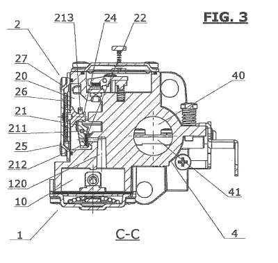
With reference now to Figure 3, the first chamber 10 is connected via a second
connecting conduit 120 to a second pressure reduction section, indicated as a
whole by the reference number 2.
According to a preferred embodiment, the second pressure reduction section 2
has similar characteristics to those of the first section 1. Consequently, in
the
zo following text, components of the second section that are similar to
those used in
the first section 1 will, where appropriate, be given the same names as those
used previously and will be identified by the adjective "second".
Thus the second section preferably comprises a second chamber 20 formed
directly in the main body 101, a second deformable diaphragm 25 which forms a
sealing wall of the second chamber 20, and a second shutter device 21 adapted
CA 02966064 2017-04-27
WO 2016/066715
PCT/EP2015/075037
6
to selectively close the second connecting conduit 120. The second shutter
device 21 is therefore connected for operation to the second deformable
diaphragm 25 in such a way that the opening of the second shutter device 21
causes the second diaphragm 25 to be deformed so as to reduce the volume
formed by the second chamber 20. This movement is opposed by corresponding
resilient means 26.
Preferably, in this case also, the shutter device 21 is made in the form of a
lever,
with similar characteristics to those described in relation to the first
pressure
reduction section. The lever is therefore pivoted on a pin 211 fixed to a base
wall
of the chamber 20, in such a way that an end 212, in which the sealing element
22 is housed, and an end 213 opposed thereto, and connected to the diaphragm
25 by a connecting element 24, can oscillate in opposite directions about the
axis
of the lever, defined by the pin 211.
With reference now to Figure 4, the carburettor according to the present
invention further comprises a supply section 3 connected to the second
pressure
reduction section 2 by a connecting conduit 130, which puts the second chamber
into communication with a third chamber 30 of the supply section.
Advantageously, the third chamber 30 is also formed directly in the main body
101, in a similar way to the chambers forming the sections described above.
zo The supply section 3 further comprises a third deformable diaphragm 35
which
forms a sealing wall of the third chamber 30. The connecting conduit 130 can
be
closed selectively by means of a third shutter device 31 which is connected
for
operation to the third deformable diaphragm 35 in such a way that the opening
of the third shutter device 31 causes the deformable diaphragm 35 to be
deformed so as to reduce the volume formed by the second chamber 30.
CA 02966064 2017-04-27
WO 2016/066715
PCT/EP2015/075037
7
According to a preferred embodiment, the supply section 3 comprises resilient
means 36, preferably made in the form of a helical spring extending between
the
third shutter device 31 and a base wall of the chamber 30 as will be better
shown in the following.
More generally, the resilient means 36 are made in such a way that they oppose
the deformation of the second deformable diaphragm 35.
According to the embodiment described above, the part of the diaphragm 35
facing towards the outside of the chamber 30 can be pushed by an actuating
device 6, formed, in the present embodiment, by a pin 60, which is slidable
within an opening formed in a shell-like wall 37 covering the deformable
diaphragm 35. Preferably, the actuating device 6 further comprises a resilient
element 61 adapted to push the pin outwards and to oppose the sliding of the
pin towards the inside of the chamber 30. Furthermore, the shell-like wall 37
is
also provided with a calibrated air returning hole 39, i.e. a hole with
calibrated
diameter, allowing the deformable diaphragm to operate without being impaired
by depressions that might occur in the chamber since it provides air at
atmospheric pressure to the deformable diaphragm.
The pin 60 therefore enables the diaphragm 35 to be pushed from the outside
towards the inside of the chamber 30, where it acts on the shutter 31 in the
zo direction of opening the conduit 130.
As described in greater detail below, the shutter 31 and the corresponding
resilient means 36 are made and dimensioned in such a way that they are
normally open when the engine in which the carburettor is used is started.
The actuating device 6 is mainly directed to make the start of the engine
easier,
since it is possible to force the shutter 31 in the open position by acting on
the
CA 02966064 2017-04-27
WO 2016/066715
PCT/EP2015/075037
8
pin 60. This allows gas to flow into the chamber 30 even when the engine is
turned off and enriching the air/fuel mixture during start.
However, it may be difficult to open the shutter because of the presence of
dust
or dirt in general in the chamber 30, which will impede the starting of the
engine,
but the shutter can be forced to open by means of the actuating button 6 so as
to allow the passage of gas and promote the starting of the engine.
Always with reference to Figure 4, it may be noted that, preferably, in the
supply
section 3 also, the shutter device 31 is made in the form of a lever, with
similar
characteristics to those described in relation to the first pressure reduction
section. The lever is therefore pivoted on a pin 311 fixed to a base wall of
the
chamber 30, in such a way that an end 312, in which the sealing element 32 is
housed, and an end 313 opposed thereto, and connected to the diaphragm 35 by
a connecting element 34, can oscillate in opposite directions about the axis
of the
lever, defined by the pin 311.
As previously outlined, according to a preferred embodiment, the resilient
means
36 extend between a metallic insert 38 abutting onto the end 313 of the
shutter
device 31 and the base wall of the chamber 30.
Preferably, the conduit 130 is associated with an adjustable nozzle 7, which
is,
for example, associated with the conduit by means of a threaded connection.
zo Thus the position of the outlet aperture 70 facing the chamber 30 can be
adjusted so as to move it towards or away from the base wall of the chamber
30.
Because of this characteristic, therefore, the closing position of the shutter
31
can be varied by modifying the load of the resilient means in the closed
position.
Thanks to the presence of the adjustable nozzle 7, it is possible to
compensate
possible inaccuracies of the base wall of the chamber 30 by varying the height
of
CA 02966064 2017-04-27
WO 2016/066715
PCT/EP2015/075037
9
the nozzle 7 itself. This is particularly advantageous since the shutter with
the
respective elastic means require very strict tolerance in order to operate
properly.
With reference now to Figure 5, the carburettor according to the present
invention further comprises a Venturi device 4 connected to the chamber 30 by
means of a supply conduit 150. .
The Venturi device 4 is essentially formed by a conduit 40 with a variable
cross
section, such that the variation in the cross section can be used to create a
pressure difference capable of drawing a flow of gas from the supply conduit
150.
Air is therefore passed through the conduit and mixed with the gas supplied
from
the supply conduit 150, and the resulting mixture is sent to the engine.
The device 4 further comprises a butterfly member 41 for regulating both the
air
flow and the gas flow. More precisely, the butterfly member 41 adjusts the air
flow by means of the butterfly disk 414, which is operated by an external
lever
system 410 connected to an upper end 412 of the butterfly member 41, i.e. the
end directed outside the carburettor body, interfacing to an engine adjustment
system, not shown in the Figures.
The gas flow is instead adjusted through a passage 411 defined at the lower
end
zo 413 of the butterfly member 41,( i.e. the end opposed to the one to
which the
lever system 410 is connected), intersecting the supply conduit 150.
A further adjustment of the air/fuel ratio, according to a preferred
embodiment,
is obtained by the air/gas mixture adjusting device 44 shown in Figure 6. The
adjusting device 44 chokes a supply conduit 160 allowing the gas to flow from
the chamber 30 to the conduit 40. Preferably, the adjusting device 44
comprises
CA 02966064 2017-04-27
WO 2016/066715
PCT/EP2015/075037
a screw 441 having appropriate diameter and length and an elastic member 442
adapted to push outwards the screw and avoid unintentional modification in the
adjusting device that might be caused by the vibrations.
With reference to Figures 1A to 1E again, the arrangement of the aforesaid
5 components is such that the Venturi device 4 forms a central portion of
the
carburettor 100.
The conduit of the Venturi device defines an axis of longitudinal extension x.
The arrangement of the other components with respect to the Venturi conduit 4
is such that the first pressure reduction section 1 and the supply section 3
10 extend on opposite sides of the axis of longitudinal extension x.
On the other hand, the second supply section 2 is interposed between the first
pressure reduction section 1 and the supply section 3.
Additionally, according to a preferred embodiment, the main body 101 has five
faces, each face being perpendicular to the faces adjacent to it, and
therefore
has an orientation similar to that of a parallelepiped. In this configuration,
the
chambers 10 and 30, respectively, of the first section 1 and of the supply
section
are formed on opposite faces, while the chamber 20 of the second section 2 is
in
the face adjacent to the aforesaid two faces.
The remaining two faces form an intake section and an outlet section of the
zo Venturi conduit 40.
Alternative embodiments of the carburettor according to the present invention
will be now described with reference to Figure 7 to 9. To this regard, it
should be
note that the following embodiments will be described only with reference to
the
features differentiating them from the previously described embodiment.
Therefore, unless explicitly stated, the same feature of the previous
embodiment
CA 02966064 2017-04-27
WO 2016/066715
PCT/EP2015/075037
11
also apply to the following ones.
With reference to Figures 7 and 7A, according to an first alternative
embodiment,
an adjusting nozzle 33 can be provided within the chamber 30, at the inlet of
the
conduit 150 connecting the chamber 30 with the Venturi conduit 40. The
adjusting nozzle 33 has a calibrated diameter, so that it is possible to
adjust the
amount of gas flown through the conduit 150.
Preferably, the adjusting nozzle 33 comprises a threaded body for connecting
it
to the conduit 150 having, to this end, a corresponding female thread.
With reference to Figures 8 and 8A, according to a second alternative
embodiment, a valve member 5 can be provided in the main body 101, allowing
a further adjustment of the flow rate through the supply conduit 140
connecting
the chamber 30 and the Venturi conduit 40.
Finally, with reference to Figure 9, a threaded member 45, e.g. a screw, is
provided on the main body 101 at a strike portion 43 of the lever system 410
corresponding to position of the lever system 410 in which the Venturi conduit
40
is fully open (i.e. the butterfly body 41 is parallel to the axis of
longitudinal
extension x).
In this manner, the threaded member 45 allows to further adjust the size of
the
section available for the passage of air in the conduit 40 and of gas in
conduit
zo 150.
Thus the invention resolves the problem which was proposed, while providing a
number of advantages. In particular, because of the configuration described
above, the main body can advantageously be produced from a single initial
block, thereby providing a highly compact and functional carburettor.
Also, the particularly compact structure makes the carburettor highly
adaptable,
CA 02966064 2017-04-27
WO 2016/066715 PCT/EP2015/075037
12
thus making it particularly suitable for the conversion of existing petrol
engines.
Additionally, the correct functioning of the carburettor is ensured even in
rather
unfavourable operating conditions, such as dusty environments.