Note: Descriptions are shown in the official language in which they were submitted.
CA 2966118 2017-05-05
1
RETRACTABLE VACUUM HOSE REEL ASSEMBLY
FIELD OF TECHNOLOGY
[0001] The present technology relates to retractable vacuum hose reel
assemblies.
BACKGROUND
[0002] Many industries, such as the automotive care industry, require the
use of vacuum
cleaners. Many such industries use portable vacuum cleaners that incorporate
the vacuum motor
and the waste container. A relatively short vacuum hose extends from the
vacuum cleaner.
[0003] Although such portable vacuum cleaners are convenient and are
relatively
inexpensive, they have some draw backs. In order to clean different areas, the
entire vacuum
cleaner needs to be moved around. During and after use, the vacuum cleaner,
the vacuum hose,
the power cord of the vacuum cleaner and, if used, a power cord extension, are
all possible
tripping hazard. Also, in order to facilitate their displacement, the portable
vacuum cleaners are
often provided with swivelling wheels. However, this means that the vacuum
cleaner could
accidentally and damage objects in its environment. For example, a person
cleaning the inside of
a car could pull on the vacuum hose and, as a result, pull on the vacuum
cleaner that could roll
into the side of the car and damage it. Also, portable vacuum cleaners are
noisy and, due to their
relatively short vacuum hoses, the user is exposed to this noise.
[0004] In order to address at least some of the above drawbacks, many
industries prefer to use
central vacuum cleaners. The vacuum motor and the waste container of the
central vacuum
cleaner are typically installed in a fixed location that is remote from the
area that needs to be
vacuumed. As such, they are no longer a tripping hazard. A relatively long
vacuum hose is
connected to a vacuum outlet that communicates with the vacuum cleaner. As a
result, handling
is facilitated as the user only needs to carry around the vacuum hose. Also,
since the vacuum
motor is provided remotely, the user is less exposed or not exposed to its
noise.
[0005] However, the long vacuum hoses used with central vacuums can still
be tripping
hazards. To address this problem, a vacuum hose reel assembly can be provided
that allow the
vacuum hose to be easily put away when not in use by winding the vacuum hose
about the reel.
9701130_1
9701130.1
CA 2966118 2017-05-05
2
[0006] Some vacuum hose reel assemblies are retractable, meaning that the
user does not
need to manually turn the reel in order to wind the vacuum. As would be
understood, this is very
convenient to the user. In some implementations, the vacuum hose reel assembly
includes a
spring that is wound as the vacuum hose is unwound from the coil. When the
user is done with
the vacuum hose, the user releases the energy stored in the spring, by giving
a quick tug on the
vacuum hose or by some other means depending on the implementation, causing
the spring to
unwind and to turn the reel to wind the vacuum hose about the reel. However,
in some such
vacuum hose reel assemblies, the forces applied to the spring as it unwinds or
when the reel
comes to a sudden stop, may cause the spring to break. This is especially true
when very long
hoses are used since the force of the spring and the mass of the vacuum hose
are greater. Also,
the type of matter to be aspirated and a height at which the vacuum hose reel
assembly is to be
installed also have an effect on the forces that are applied to the spring.
For example, aspirating
water using a vacuum hose mounted to a vacuum hose reel mounted 7 meters high
applies more
forces on than aspirating dust using a vacuum hose mounted to a vacuum hose
reel mounted 3
meters high. These forces could also potentially cause failure of the spring.
[0007] There is therefore a desire for a retractable vacuum hose reel
using a spring assembly
that addresses at least some of the above drawbacks.
SUMMARY
[0008] It is an object of the present technology to ameliorate at least
some of the
inconveniences present in the prior art.
[0009] According to an aspect of the present technology, there is
provided a vacuum hose reel
assembly that has a spiral torsion spring. One end portion of the spiral
torsion spring is received
in a slot defined by a spring holder. As the vacuum hose is unwound from the
reel, the spring is
wound as the reel turns in a first direction. To wind the vacuum hose back on
the reel, the spring
unwinds and turns the reel in a second, opposite, direction. In the event that
the forces between
the end portion of the spring and the spring holder become too high, the end
portion of the spring
disengages the spring holder such that the end portion of the spring turns
about the spring holder,
9701130_1
9701130 1
CA 2966118 2017-05-05
3
thereby preventing the spring from breaking. Unwinding the vacuum hose causes
the end
portion of the spring to reengage the spring holder.
[0010] According to one aspect of the present technology, there is
provided a vacuum hose
reel assembly having a rotationally fixed axle, a reel rotationally mounted to
the axle, and a
spring assembly operatively connected between the axle and the reel. The
spring assembly is
adapted for turning the reel in order to wind a vacuum hose on the reel. The
spring assembly has
a spring holder connected to and being rotationally fixed relative to the
axle, and a spiral torsion
spring. The spring holder has first and second walls. The first and second
walls define a slot
therebetween. The first wall extends radially further from a center of the
axle than the second
wall. The spring holder has an outer surface extending from a radially outer
end of the first wall
to a radially outer end of the second wall. The spiral torsion spring has an
outer end portion
operatively engaging the reel, and an inner end portion selectively
operatively engaging the
spring holder. The inner end portion being selectively received in the slot of
the spring holder.
When the reel turns in a first direction to unwind the vacuum hose from the
reel, the inner end
portion of the spiral torsion spring is disposed in the slot and abuts the
first wall, and the spiral
torsion spring is wound. When the spiral torsion spring turns the reel in a
second direction,
opposite the first direction, to wind the vacuum hose on the reel, the inner
end portion of the
spiral torsion spring is disposed in the slot and abuts the second wall, and
the spiral torsion
spring unwinds. When a force between the inner end portion of the spiral
torsion spring and the
second wall exceeds a predetermined force while the reel turns in the second
direction, the inner
end portion of the spiral torsion spring disengages the spring holder by
coming out of the slot
and then turns about the spring holder, and the inner end portion of the
spiral torsion spring abuts
the outer surface of the spring holder as the inner end portion turns over at
least a portion of a
rotation.
[0011] According to another aspect of the present technology, the outer
surface of the spring
holder has a shape of a segment of a spiral.
=
[0012] According to another aspect of the present technology, a radially
inner end of the first
wall of the spring holder is radially spaced from the axle. The spring holder
has an inner surface
extending from the radially inner end of the first wall away from the second
wall. The inner
9701130_1
9701130 I
CA 2966118 2017-05-05
4
surface is radially spaced from the axle. The inner surface of the spring
holder and the axle
define a space radially therebetween. The space communicates with the slot.
When the inner
end portion of the spiral torsion spring is disposed in the slot, the inner
end portion of the spiral
torsion spring is disposed in the space.
[0013] According to another aspect of the present technology, the inner end
portion of the
spiral torsion spring is hook-shaped.
[0014] According to another aspect of the present technology, the
radially inner end of the
first wall is radially further from the center of the axle than the radially
outer end of the second
wall.
[0015] According to another aspect of the present technology, a side of the
reel defines a
recess, and the spring assembly is disposed in the recess.
[0016] According to another aspect of the present technology, the spring
assembly has a
spring housing. The spiral torsion spring is disposed in the spring housing.
The spring housing
has an eccentric contour. The outer end portion of the spiral torsion spring
is disposed in a
portion of the spring housing defined by a portion of the eccentric contour
being furthest from a
central axis of the reel.
[0017] According to another aspect of the present technology, a ratchet
assembly is
operatively connected to the reel and selectively prevents turning of the reel
to wind the vacuum
hose.
[0018] According to another aspect of the present technology, the ratchet
assembly and the
spring assembly are disposed on opposite sides of the reel.
[0019] According to another aspect of the present technology, the ratchet
assembly has a plate
connected to a side of the reel. The plate defines a central aperture. The
plate defines internal
ratchet teeth over only a portion of a contour of the central aperture.
9701130_1
9701130 1
CA 2966118 2017-05-05
[0020] According to another aspect of the present technology, the axle is
hollow. A first end
of the axle is adapted for fluidly communicating with a vacuum cleaner. A
second end of the
axle is adapted for fluidly communicating with the vacuum hose.
[0021] According to another aspect of the present technology, the vacuum
hose is provided
5 and fluidly connects to the second end of the axle.
[0022] According to another aspect of the present technology, the vacuum
hose extends from
the second end of the axle outside the reel, extends through a side of the
reel, and is selectively
wound about the reel.
[0023] According to another aspect of the present technology, a seal
assembly disposed over
the second end of the axle. The vacuum hose is connected to the seal assembly.
[0024] According to another aspect of the present technology, the seal
assembly is connected
to and turns with the reel.
[0025] According to another aspect of the present technology, at least
one fluid hose extends
inside the axle and at least partially inside the vacuum hose.
[0026] According to another aspect of the present technology, the at least
one fluid hose is
one of at least one water hose and at least one pressurized air hose.
[0027] According to another aspect of the present technology, a guide
assembly is connected
to the axle. The guide assembly defines a guide passage. A hose stopper is
connected to an end
of the vacuum hose. The vacuum hose extends through the guide passage. The
hose stopper is
dimensioned so as to not pass through the guide passage.
[0028] According to another aspect of the present technology, a mounting
bracket is
connected to the axle. A guide assembly is connected to the mounting bracket
in at least one of a
first configuration and a second configuration. The guide assembly includes a
guide adapted to
receive the vacuum hose extending from the reel therethrough. In the first
configuration the
guide guides the vacuum hose generally horizontally. In the second
configuration the guide
guides the vacuum hose generally vertically.
9701130_1
9701130.1
CA 2966118 2017-05-05
6
[0029] According to another aspect of the present technology, at least
one ball bearing is
disposed between the axle and the reel for rotationally supporting the reel
about the axle.
[0030] According to another aspect of the present technology, the at
least one ball bearing is
two ball bearings.
[0031] Implementations of the present technology each have at least one of
the above-
mentioned object and/or aspects, but do not necessarily have all of them. It
should be understood
that some aspects of the present technology that have resulted from attempting
to attain the
above-mentioned object may not satisfy this object and/or may satisfy other
objects not
specifically recited herein.
[0032] Additional and/or alternative features, aspects and advantages of
implementations of
the present technology will become apparent from the following description,
the accompanying
drawings and the appended claims.
BRIEF DESCRIPTION OF THE DRAWINGS
[0033] For a better understanding of the present technology, as well as
other aspects and
further features thereof, reference is made to the following description which
is to be used in
conjunction with the accompanying drawings, where:
[0034] Figure 1 is a perspective view take from a front, left side of a
retractable vacuum hose
reel assembly in a wall mounting configuration;
[0035] Figure 2 is a left side elevation view of the retractable vacuum
hose reel assembly of
Fig. 1 in a ceiling mounting configuration;
[0036] Figure 3 is a perspective view take from a front, left side of the
retractable vacuum
hose reel assembly of Fig. 1 in an alternative wall mounting configuration;
[0037] Figure 4 is a right side elevation view of the retractable vacuum
hose reel assembly of
Fig. 1;
9701130_1
9701130.1
CA 2966118 2017-05-05
7
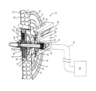
[0038] Figure 5 is a cross-sectional view of the retractable
vacuum hose reel assembly of Fig.
1 schematically illustrating a connection of the retractable vacuum hose reel
assembly to a
vacuum cleaner;
[0039] Figure 6 is a close-up view of a left side of the
retractable vacuum hose reel assembly
of Fig. 1 with some components removed for showing a ratchet assembly of the
retractable
vacuum hose reel assembly;
[0040] Figure 7 is a close-up view of a right side of the reel of
the retractable vacuum hose
reel assembly of Fig. 1 with some components removed for showing a spring
assembly of the
retractable vacuum hose reel assembly;
[0041] Figure 8 is a perspective view of a spring holder of the retractable
vacuum hose reel
assembly of Fig. 1;
[0042] Figure 9 is a right side elevation view of the spring
holder of Fig. 8;
[0043] Figure 10 is a cross-sectional view of the spring holder of
Fig. 8 taken through line 10-
10 of Fig. 9;
[0044] Figure 11A is a right side elevation view of the spring holder of
Fig. 8 and an end
= portion of the spring of the spring assembly of Fig. 7 during unwinding
of a vacuum hose of the
retractable vacuum hose reel assembly of Fig. 1;
[0045] Figure 11B is a right side elevation view of the spring
holder and the end portion of
the spring of Fig. 11A during winding of the vacuum hose with a reel of the
retractable vacuum
hose reel assembly of Fig. 1 turning slower than a predetermined speed;
[0046] Figure 11C is a right side elevation view of the spring
holder and the end portion of
the spring of Fig. 11A during winding of the vacuum hose when a force between
the end portion
of the spring and the spring holder becomes too high;
[0047] Figure 12 is a perspective view take from a front, left
side of an alternative
implementation of the retractable vacuum hose reel assembly of Fig. 1
including a fluid hose;
9701130_1
9701130.1
CA 2966118 2017-05-05
8
[0048] Figure 13 is a right side elevation view of the retractable
vacuum hose reel assembly
of Fig. 12;
[0049] Figure 14 is a front elevation view of the retractable
vacuum hose reel assembly of
Fig. 12;
[0050] Figure 15 is a cross-sectional view of the retractable vacuum hose
reel assembly of
Fig. 12; and
[0051] Figure 16 is a top, front, left side perspective view
illustrating a hose stopper
accessory connected to an end of the vacuum hose of the retractable vacuum
hose reel assembly
of Fig. 12.
DETAILED DESCRIPTION
[0052] With reference to Figs. 1 to 5, a vacuum hose reel assembly
10 has a reel 12
rotationally mounted on an axle 14. The axle 14 is connected to a mounting
bracket 16. A
vacuum hose 18 is wound about the reel 12. A guide assembly 20 is connected to
the mounting
bracket 16. The guide assembly 20 has a guide 22 through which the vacuum hose
18 extends,
such that the guide 22 guides the vacuum hose 18 as it is being wound onto and
unwound from
the reel 12.
[0053] The mounting bracket 16 is generally L-shaped. One side of
the mounting bracket 16
defines a plurality of apertures 24 (only one of which can be seen in Figs. 1
and 3). Fasteners
(not shown), such as bolts, are inserted through the apertures 24 to fasten
the mounting bracket
= 20 16, and therefore the vacuum hose reel assembly 10, to a
mounting surface. The mounting
bracket 16 can be used to mount the vacuum hose reel assembly 10 in a wall
mounting
configuration as shown in Figs. 1 and 3 or in a ceiling mounting configuration
as shown in Fig.
2. Although they are being referred to herein as wall and ceiling mounting
configurations, it
should be understood that these configurations are not intended to limit the
mounting of the
vacuum hose reel assembly 10 to a wall or to a ceiling. Rather, the wall
mounting configuration
is intended to indicate that the mounting bracket 16 can be mounted to a wall,
but also to other
vertically extending structures, such as a mast for example. Similarly, the
ceiling mounting
9701130_1
9701130.1
CA 2966118 2017-05-05
9
configuration is intended to indicate that the mounting bracket 16 can be
mounted to a ceiling,
but also to other horizontally extending structures, such as a beam for
example. It is also
contemplated that the mounting bracket 16 could be fastened that are not
vertical or horizontal.
[0054] The guide assembly 20 has a guide arm 26 connected to the mounting
bracket 16 at
one end. The guide 22 is connected to the guide arm 26 at the opposite end of
the guide arm. As
can be seen in Figs. 1 to 3, the guide assembly 20 can be arranged in multiple
configurations. In
the configuration illustrated in Fig. 1, the guide arm 26 is connected to the
mounting bracket 16
so as to extend downward and forward from the mounting bracket 16 and the
guide 22 is
connected to the end of the guide arm 26 such that the vacuum hose 18 is
guided generally
I() horizontally by the guide 22. In the configuration illustrated in Figs.
2 and 3, the guide arm 26 is
connected to the mounting bracket 16 so as to extend downward and rearward
from the mounting
bracket 16 and the guide 22 is connected to the end of the guide arm 26 such
that the vacuum
hose 18 is guided generally vertically by the guide 22. Other configurations
of the guide
assembly 20 are contemplated. For example it is contemplated that in an
alternative
configuration not illustrated herein, the guide arm 26 is connected to the
mounting bracket 16 so
as to extend downward and forward from the mounting bracket 16 and the guide
22 is connected
to the end of the guide arm 26 such that the vacuum hose 18 is guided
generally vertically by the
guide 22.
[0055] The configuration of the mounting bracket 16 and of the guide
assembly 20 is selected
based on the location where the vacuum hose reel assembly 10 is to be
installed. For simplicity,
the remainder of the description of the vacuum hose reel assembly 10 will be
made with respect
to the configuration of the mounting bracket 16 and of the guide assembly 20
illustrated in Fig.
1.
[0056] The guide 22 includes a roller housing 28. The roller housing 28
is fastened to the end
of the guide arm 26. Four rollers 30 are mounted to the roller housing 28. The
rollers 30 are
arranged so as to form a generally square guide passage 32 therebetween. The
vacuum hose 18
passes through the guide passage 32. The diameter of the vacuum hose 18 is
smaller than the
length of the sides of the guide passage 32 (i.e. the distance between opposed
rollers). As the
vacuum hose 18 passes through the guide passage 32 it comes into contact with
one or more of
9701130_1
9701130.1
CA 2966118 2017-05-05
the rollers 30 as the guide 22 guides the vacuum hose 18. It is contemplated
that the rollers 30
could be omitted, but the presence of the rollers 30 help reduce wear of the
vacuum hose 18 as it
passes through the guide passage 32 and the forces required to unwind and
winding the vacuum
hose 18 as there is less friction. It is contemplated that more of less than
four rollers 30 could be
5 provided. For example, three rollers 30 could be arranged so as to form a
generally triangular
guide passage 32. It is also contemplated that the rollers 30 could be
replaced by non-rolling
sliders or a sleeve made of a low friction plastic or similar material.
[0057] To stop the reel 12 from winding the vacuum hose 18 too far, which
would then
require the user to thread the vacuum hose 18 through the guide passage every
time the user
10 wants to use the vacuum hose, a stopper clip 34 is attached to the
contour of the vacuum hose 18.
The diameter of the stopper clip 34 is greater than the size of the guide
passage 32. As such, as
the vacuum hose 18 is wound on the reel 12, the stopper clip 34 will
eventually come into
contact with the rollers 30, as shown in Fig. 4, thereby preventing the vacuum
hose 18 from
winding any further on the reel 12. The stopper clip 34 can be located at any
desired location
along the vacuum hose 18, but it is typically located at a location on the
vacuum hose 18 that will
leave a length of vacuum hose 18 extending from the guide 22 that is
sufficiently long to easily
reach the vacuum hose 18 when the stopper clip 34 contacts the guide passage
32.
[0058] As can be seen in Fig. 5, the reel 12 is from two reel halves 36
that are fastened to
each other. Each reel half 36 has a radially outer hose guide portion 38 and a
central recessed
portion 40. The central recessed portions 40 abut each other and are fastened
to each other to
form the reel 12. When the vacuum hose 18 is wound on the reel 12, as seen in
Fig. 5, the
vacuum hose 18 is disposed laterally between the hose guide portions 28 and
rests on the
portions 42 of the reel halves 36 joining each hose guide portion 38 to its
corresponding central
recessed portion 40.
[0059] Each reel half 36 defines a central aperture through which a sleeve
44, which forms
part of the reel 12, is inserted. The sleeve 44 is connected to the reel
halves 36 and extends on a
left side of the central recessed portion 40 of the of the left reel half 36.
The sleeve 44 defines an
outer shoulder 46 that abuts the left side of the central recessed portion 40
of the of the left reel
half 36. Two ball bearings 48 are disposed between the sleeve 44 and the axle
14 to rotationally
9701130_1
9701130 1
CA 2966118 2017-05-05
11
mount the reel 12 to the axle 14, thus allowing the reel 12 to turn about the
axle 14. It is
contemplated that only one or more than two ball bearings 48 could be
provided.
[0060] The left end portion of the axle 14 extends through apertures
defined in a plate 50, the
mounting bracket 16 and the guide arm 16. As can be seen in Fig. 5, the plate
50 is fastened to
the mounting bracket 16. The axle 14 is connected to the plate 50 so as to be
rotationally fixed.
As can be seen, the axle 14 is hollow. A vacuum hose connector 52 is provided
over the left end
portion of the axle 14. The vacuum hose connector 52 has internal threads. A
vacuum hose 54
is threaded into the vacuum hose connector 52 at one end and is connected to a
vacuum cleaner
56 (schematically shown in Fig. 5) at the other end. The vacuum hose 54 has an
internal
diameter that is bigger than the internal diameters of the vacuum hose 18 and
the axle 14, but it is
contemplated that it could be the same. It is contemplated that vacuum hose
connector 52 and
the vacuum hose 54 could be replaced by a pipe connector and one or more rigid
pipes to fluidly
connected the axle 14 to the vacuum cleaner 56. It is also contemplated that a
combination of
vacuum hose(s) and rigid pipe(s) could be used to fluidly connected the axle
14 to the vacuum
cleaner 56.
[0061] As can be seen in Fig. 5, a seal assembly 58 is provided over the
right end portion of
the axle 14. The seal assembly 58 includes a sleeve 60, a mounting flange 62
and a lip seal 64.
In the present implementation, the sleeve and the mounting flange 62 are
integrally formed, but it
is contemplated that they could be connected to each other otherwise. The
sleeve 60 has internal
threads that are engaged by outer threads formed on the end of the vacuum hose
18, thereby
connecting the vacuum hose 18 to the seal assembly 58. The lip seal 64 is in
contact with the
contour of axle 14. The lip seal 64 preventing outside air from entering the
passage provided
inside the axle 14 via the interface between the ends of the vacuum hose 18
and the axle 14 when
the vacuum cleaner 56 is in operation, which would reduce the efficiency of
the vacuum cleaner
56. In fact, during operation of the vacuum cleaner 56, the pressure inside
the vacuum hose 18
and the axle 14 is lower than the ambient pressure, thus pressing the lip seal
64 against the
contour of the axle 14, thereby improving the seal provided by the lip seal
64. As best seen in
Fig. 4, the mounting flange 62 is fastened by three butterfly fasteners 66 to
a cover 68. The use
of butterfly fasteners 66 allow the mounting and removal of the seal assembly
58 without the use
of tools. It is contemplated that more or less than three fasteners 66 could
be used and that the
9701130_1
97011301
CA 2966118 2017-05-05
12
butterfly fasteners 66 could be replaced by another type of fastener. The
cover 68 is provided
over the recess 70 defined by the central recessed portion 40 of the right
reel half 36. The cover
68 is fastened to the hose guide portion 38 of the right reel half 36. As a
result, the cover 68, the
seal assembly 58 and the vacuum hose 18 turn together relative to the axle 14.
It is contemplated
that the seal assembly 58 could be replaced by a different type of seal
assembly.
[0062] From the seal assembly 58, the vacuum hose 18 passes through an
aperture 72 (Fig. 4)
defined in the hose guide portion 38 of the right reel half 36 of the reel 12
and is wound about
the reel 12
[0063] During use of the vacuum cleaner 56, dirt, debris, liquid and/or
any other thing
aspirated flows consecutively through the vacuum hose 18, the axle 14 and the
vacuum hose 54
before reaching the vacuum cleaner 56.
[0064] The vacuum hose reel assembly 10 is provided with a ratchet
assembly 80 (Fig. 6) and
a spring assembly 100 (Fig. 7). The ratchet assembly 80 is provided on a left
side of the reel 12
and the spring assembly 100 is provided on a right side of the reel 12. It is
contemplated that the
ratchet assembly 80 could be provided on a right side of the reel 12 and that
the spring assembly
100 could be provided on a left side of the reel 12. It is also contemplated
that in some
implementations, the ratchet assembly 80 and the spring assembly 100 could be
provided on the
same side of the reel 12.
[0065] The functions of the ratchet assembly 80 and the spring assembly
100 will now be
described. Details regarding ,the construction of the ratchet assembly 80 and
the spring assembly
100 will be provided further below.
[0066] As a user pulls on the vacuum hose 18 to unwind from the reel 12,
the reel 12 turns
clockwise (as viewed from the left side of the vacuum hose reel assembly 10 in
the configuration
shown in Fig. 1). As the reel 12 turns clockwise, a spring 102 of the spring
assembly 100 is
wound. When the user stops pulling on the vacuum hose 18, the ratchet assembly
80 prevents
the reel 12 from starting to turn counter-clockwise (as viewed from the left
side of the vacuum
hose reel assembly 10 in the configuration shown in Fig. 1) by the force
applied to the reel 12 by
the spring 102. Thus, the ratchet assembly 80 prevents the vacuum hose 18 from
being wound
9701130_1
9701130 1
CA 2966118 2017-05-05
13
back on the reel 12 when the user stops pulling on the vacuum hose 18. As
would be
understood, when the user stops pulling on the vacuum hose 18, the reel 12
will turn slightly due
to backlash resulting from the design of the ratchet assembly 80 and the
vacuum hose 18 will
therefore retract slightly, but the reel 12 will not complete a full
revolution or more.
[0067] In order to wind the vacuum hose 18 back on the reel 12, the user
tugs on the vacuum
hose 18 and then releases the vacuum hose 18 causing the ratchet assembly 80
to disengage thus
allowing the energy stored in the spring 102 to turn the reel 12 counter-
clockwise (as viewed
from the left side of the vacuum hose reel assembly 10 in the configuration
shown in Fig. 1). As
= the reel 12 turns counter-clockwise, the vacuum hose 18 is wound back on
the reel 12. It is
contemplated that alternative implementations of the ratchet assembly 80 could
be disengaged by
actuating a mechanical device such as a release lever rather than by tugging
on the vacuum hose
18. It is also contemplated that the ratchet assembly 80 could be replaced by
another type of
mechanism for selectively preventing the vacuum hose 18 from winding back on
the reel 12.
[0068] Turning now to Fig. 6, the ratchet assembly 80 will be
described in more detail. The
= 15 ratchet assembly 80 includes a plate 82, a pawl 84, a spring 86
and a mounting member 88. The
plate 82 is fastened to the hose guide portion 38 of the left reel half 36.
The plate 82 defines a
central aperture 90. A plurality of internal ratchet teeth 92 (only some ow
which are labeled for
clarity in the Figures) are defined over half of the contour of the aperture
90. It is contemplated
that ratchet teeth 92 could provided over more or less than half of the
contour of the aperture 90.
It is also contemplated that more or less ratchet teeth 92 than illustrated
could be provided. The
distance between each ratchet teeth 92 determines the amount of backlash of
the ratchet
assembly 80. The pawl 84 is pivotally connected to the mounting member 88. The
pawl 84, as
can be seen in Fig. 6, has a convex side and a concave side that meet at a tip
of the pawl 84. In
one implementation, the pawl 84 is made from a material that is harder than
the ratchet teeth 92.
In one implementation, the pawl 84 is made from hardened steel, but other
materials are
contemplated. The spring 86 is connected between the pawl 84 and the mounting
member 88.
The spring 86 biases the pawl 84 against the portion of the contour of the
aperture 90 defining
the ratchet teeth 92 when the ratchet assembly 80 is operating to prevent
turning of the reel 12 to
wind the vacuum hose 18 (i.e. not when the use tugs on the vacuum hose 18 to
disengage the
9701130_1
9701130.1
=
CA 2966118 2017-05-05
14
ratchet assembly 80 as described above). The mounting member 88 is received in
a channel
formed in the plate 50 and is fastened to the mounting bracket 16.
[0069] When the user has unwound the vacuum hose 18 from the reel 12 to
the desired length
and stops pulling on the vacuum hose 18, the spring 102 causes the reel 12 to
turn slightly
(counter-clockwise with reference to Fig. 6) until the pawl 84, helped by the
bias of the spring
86, engages a ratchet tooth 92. The ratchet assembly 80 is designed such that
when the pawl 84
engages a ratchet tooth 92, the contact between the two parts generates a
clicking noise that is
loud enough to be heard by the user, thus giving the user an audible feedback
that the pawl 84
has engaged the ratchet tooth 92. It is contemplated that this audible
feedback feature could be
omitted. Once this occurs, the reel 12 is prevented from turning any further
in this direction.
However, pawl 84 will not prevent the vacuum hose 18 from being unwound
further and the reel
12 from turning in the corresponding direction (i.e. clockwise with reference
to Fig. 6). When
the user tugs on the vacuum hose 18 and then releases the vacuum hose 18, the
sudden pull and
release cause the pawl 84 to pivot such that it no longer engages the ratchet
teeth 92 as the reel
12 turns (counter-clockwise with reference to Fig. 6) under the action of the
spring 102 to wind
the vacuum hose 18 on the reel 12.
[0070] Turning now to Figs. 5 and 7, the spring assembly 100 will be
described in more
detail. As can be seen in Fig. 5, the spring assembly 100 is disposed in the
recess 70 defined by
the central recessed portion 40 of the right reel half 36. As described above,
the spring assembly
100 includes a spring 102. The spring 102 is a spiral torsion spring 102,
sometimes referred to as
a clock spring, and hereinafter referred to simply as the spring 102. The
inner end portion 104
and the outer end portion 106 of the spring 102 are hook-shaped, but it is
contemplated that they
could be bent into other shapes.
[0071] The spring assembly 100 also includes a spring housing 108 and a
spring holder 110.
The spring 102 is disposed in the spring housing 108. The spring housing 108
is fastened to and
abuts the cover 68 such that the spring 102 is held between the cover 68 and
the spring housing
108. The spring housing 108 turns together with the reel 12. The outer end
portion 106 of the
spring 102 is held between a pair of tabs 109 (Fig. 7) extending from the
cover 68 into the spring
housing 108. In one implementation, the tabs 109 are integrally formed with
and bent from the
9701130_1
9701130.1
CA 2966118 2017-05-05
cover 68. The spring holder 110 is disposed over the axle 14 and is connected
to the axle 14 so
as to be rotationally fixed relative to the axle 14. The inner end portion 104
of the spring 102
selectively engages the spring holder 110 as will be described in more detail
below. Since the
spring holder 110 is rotationally fixed relative to the axle 14 but the spring
housing 108 turns
5 with the reel 12, when the reel 12 turns to unwind the vacuum hose 108,
the spring 102 is wound.
When the ratchet assembly 80 is disengaged, the spring 102 unwinds, the outer
end portion 106
of the spring 102 pushes on the spring housing 106 which transfers the force
to the reel 12
causing the reel 12 to turn to wind the vacuum hose 108 on the reel 12.
[0072] As can be seen in Fig. 7, the spring housing 108 has a
flange 112 used for fastening
10 the spring housing 108 to the cover 68. The spring housing 108 also has
an eccentric contour
114 along the radially inner edge of the flange 112. The outer end portion 106
of the spring 102
is disposed in the portion 116 of the spring housing 108 defined by the
portion of the contour 114
that is furthest from the central axis 118 of the reel 12. It should be noted
that the central axis of
the axle 14 is coaxial with the central axis 118 of the reel 12.
15 [0073] Turning now to Figs. 8 to 11C, the spring holder 110 will be
described in more detail.
The spring holder 110 has a spring holder body 120 and a flange 122 connected
to an end of the
=
spring holder body 120. In the present implementation the spring holder body
120 and the flange
122 are integrally formed, but it is contemplated that they could be connected
by other means,
such as by welding or with fasteners. The spring holder 110 defines a central
aperture 124. The
axle 14 is inserted in this aperture 124. As can be seen in Fig. 5, the spring
holder 110 is located
on the axle 14 such that the flange 122 is located outside the spring housing
108 and the spring
holder body 120 is disposed inside the spring housing 108. The contour of the
central aperture
124 has a flat side 126. This flat side 126 is disposed over a corresponding
flat side on an outer
surface of the axle 14 (see Fig. 7), thus preventing the spring holder 110
from rotating relative to
the axle 14. It is contemplated that other means could be provided for
preventing the spring
holder 110 from rotating relative to the axle 14 such as keys or splines, or
by fastening or
welding the spring holder 110 to the axle 14. It is also contemplated that the
spring holder 110
could be integrally formed with the axle 14.
9701130_1
9701130 1
CA 2966118 2017-05-05
16
[0074] The spring holder body 120 has two end walls 128, 130 that define
a slot 132
therebetween. The end walls 128, 130 are arcuate in the present
implementation, but it is
contemplated that they could have other shapes, including flat. The end walls
128, 130 are
radially offset from each other. As best seen in Fig. 9, the end wall 128 is
radially further from
the center of the axle 14 (i.e. axis 118 in the Figures). than the end wall
130. In the present
implementation, the center of the axle 14 corresponds to the center 134 of the
spring holder 110.
As such, the outer surface 136 of the spring holder body 120 that extends
between the radially
outer ends 138, 140 of the end walls 128, 130 respectively is not circular.
The outer surface 136
has the shape of a segment of a spiral.
[0075] Also, the radially inner end 142 of the end wall 128 is radially
further from the center
134 than the radially outer end 140 of the end wall 130. As a result, the
radially inner end 136 is
radially spaced from the axle=14. The spring holder body 120 has an inner
surface 144 extending
from the radially inner end 142 of the end wall 128 away from the end wall
130. The inner
surface 144 is also radially spaced from the axle 14 so as to define a space
146 radially between
the inner surface 144 and the axle 14. The space 146 and the slot 132
communicate with each
other. In an alternative implementation, the radially inner end 142 of the end
wall 128 is not
spaced from the axle 14 and the space 146 is omitted.
[0076] The inner end portion 104 of the spring 102 is normally received
in the slot 132 and
the space 146 as shown in Figs. 11A and 11B. With reference to Fig. 11A, when
the user pulls
on the vacuum hose 18 to unwind the vacuum hose 18 from the reel 12, the reel
12 turns in the
direction indicated by the arrow 148, the inner end portion 104 of the spring
102 abuts the end
wall 128, and the spring 102 is wound. With reference to Fig. 11B, when the
ratchet assembly
80 is disengaged and the spring 102 turns the reel 12 in the direction
indicated by arrow 150 to
wind the vacuum hose 18 on the reel 12, the inner end portion 104 of spring
102 abuts the end
wall 130, and the spring 102 unwinds. With reference to Fig. 11C, when a force
between the
inner end portion 104 of the spring 102 and the end wall 130 becomes too high
(i.e. it exceeds a
force predetermined by the design of the spring assembly 100) while the reel
12 turns in the
direction indicated by arrow 150 (see Fig. 11B), the inner end portion 104 of
the spring 102
disengages the spring holder 110 by coming out of the slot 132 and the space
146. The inner end
portion 104 of the spring 102 then starts turning freely about the spring
holder body 120 in the
9701130_1
9701130.1
CA 2966118 2017-05-05
17
direction indicated by arrow 152 in Fig. 11C (i.e. the direction in which the
reel 12 turns). The
inner end portion 104 of the spring 102 abuts the outer surface 136 as it
turns about the spring
holder body 120. It is contemplated that the inner end portion 104 of the
spring 102 could abut
the outer surface 136 as it turns about the spring holder body 120 for only
part of a rotation. By
having the end portion 104 of the spring 102 disengage the spring holder 110
when the forces
between the spring holder 110 and the end portion 104 of the spring 102 become
too high,
damage to the spring 102 and possible complete failure of the spring 102 are
prevented. This
could occur while the vacuum hose 18 is being wound. This could also occur
should a user turn
the reel 12 in the hose winding direction when the spring 102 is already in
its normal, unwound
configuration, which would otherwise cause the spring 102 to be unwound
further than it was
designed to be. Once the end portion 104 of the spring 102 is disengaged from
the spring holder
= 110 as shown in Fig. 11C, turning the reel 12 in the direction opposite
to the direction indicated
by the arrow 152 in Fig. 11C causes the end portion 104 of the spring 102 to
move toward the
end wall 128. When the end portion 104 of the spring 102 reaches the end wall
128, it catches
on the end wall 128 and returns to the position shown in Fig. 11A.
[0077] Turning now to Figs. 12 to 15, a vacuum hose reel assembly
200 will now be
described. The vacuum hose reel assembly 200 is an alternative implementation
of the vacuum
hose reel assembly 1() described above. For simplicity, the components of the
vacuum hose reel
assembly 200 corresponding to those of the vacuum hose reel assembly 10 have
been labeled
with the same reference numerals in the Figures and will not be described
again in detail herein.
[0078] In the vacuum hose reel assembly 200, a fluid hose 202 is
routed inside the vacuum
hose 18. As a result, the user can conveniently wind and unwind the vacuum
hose 18 and the
fluid hose 202 simultaneously on the same reel 12. In on implementation, the
fluid hose 202 is a
water hose to supply water that may or may not be pressurized. In another
implementation, the
fluid hose 202 is a pressurized air hose to supply pressurized air.
[0079] An adaptor 204 is connected between the left end of the
axle 14 and the vacuum hose
connector 52. A fluid hose connector 206 is connected to the adaptor 204. The
fluid hose
connector 206 connects via a fluid hose (not shown) to the fluid source. The
fluid source can be
a source of pressurized or unpressurized water or a source of pressurized air
depending on the
9701130_1
9701130.1
CA 2966118 2017-05-05
18
type of fluid hose 202 being used. The fluid hose connector 206 connects to an
elbow fitting 208
(Fig. 15) located inside the adaptor 204. From the elbow fitting 208, a fluid
hose 210 extends
inside the axle 14 as can be seen in Fig. 15. As can be seen in Figs. 13 and
14, a dual branch
adaptor 212 is connected to the seal assembly 58 so as to turn with the seal
assembly 58 and the
reel 12. A vacuum hose connector 214 is connected to the branch of the dual
branch adaptor 212
that is angled relative to the axle 14. The vacuum hose connector 214 is
similar to the vacuum
hose connector 52 and will therefore not be described in detail herein. The
end of the vacuum
hose 18 is connected to the vacuum hose connector 214. A rotating fluid
connector assembly
216 is connected to the end of the branch of the dual branch adaptor 212 that
is coaxial with the
axle 14. The fluid hose 210 connects to one end of the rotating fluid
connector assembly 216.
The fluid hose 202 connects to the other end of the rotating fluid connector
assembly 216. As
the reel 12 turns, the end of the rotating fluid connector assembly 216 to
which the fluid hose
202 is connected turns with the reel 12, while the end of the rotating fluid
connector assembly
216 to which the fluid hose 2,10 is connected remains rotationally fixed, thus
preventing the fluid
hose 210 from twisting when the reel 12 turns. From the rotating fluid
connector assembly 216,
the fluid hose 202 enters the vacuum hose through an aperture 218 near the end
of the vacuum
hose 18 connected to the vacuum hose connector 214, then extends inside the
vacuum hose 18,
and exits the vacuum hose 18 through an aperture 220 near the opposite end of
the vacuum hose
18.
[0080] A hose stopper 250 is connected to the end of the vacuum hose 18.
The hose stopper
250 is provided in addition to the stopper clip 34. In the event that the
stopper clip 34
accidentally comes off the vacuum hose 18, or if the user simply forgot to
attach the stopper clip
to the vacuum hose 18, the hose stopper 250 will prevent the vacuum hose 18
from going
completely through the guide passage 32. As best seen in Fig. 16, the hose
stopper 250 of the
present implementation is frustoconical in shape. One side of the hose stopper
250 defines
internal threads 252 (schematically illustrated) to thread the hose stopper
250 onto the end of the
vacuum hose 18. The other side of the hose stopper defines a bore 254 to
receive a vacuum
accessory connector 256 therein. The vacuum accessory connector 256 is held by
friction fit
inside the bore 254, but other types of connections are contemplated. The
vacuum accessory
connector 256 permits the attachment of various vacuum accessories to the end
of the vacuum
9701130_1
9701130 1
CA 2966118 2017-05-05
19
hose 18. The largest diameter of the hose stopper 250 is greater than the size
of the guide
passage 32. As such, should the stopper clip 34 be missing, as the vacuum hose
18 is wound on
the reel 12, the hose stopper 250 will eventually come into contact with the
rollers 30, thereby
preventing the vacuum hose 18 from passing completely through the guide
passage 32. It is
contemplated that the hose stopper 250 could have other shapes as long as it
is dimensioned so as
to not pass through the guide passage 32. It is contemplated that the hose
stopper 250 could also
be connected to the end of the vacuum hose 18 of the vacuum hose reel assembly
10.
[0081] It is contemplated that the vacuum hose reel assemblies 10 and 200
described above
could be provided without the hoses 18, 202 and the user could then connect
suitable hoses 18,
202 of his or her choosing to the vacuum hose reel assemblies 10, 200. It is
also contemplated
that the vacuum hose reel assemblies 10 and 200 could be mirror images from
the way they are
illustrated in the Figures.
[0082] Modifications and improvements to the above-described
implementations of the
present technology may become apparent to those skilled in the art. The
foregoing description is
intended to be exemplary rather than limiting. The scope of the present
technology is therefore
intended to be limited solely by the scope of the appended claims.
9701130_1
970113o l