Note: Descriptions are shown in the official language in which they were submitted.
CA 2966160 2017-05-04
FLUID DISPENSING CATHETER
Background
1. Technical Field
[0001] The present disclosure relates to surgical instruments and, more
specifically, to catheters for dispensing fluids at a surgical site.
2. Discussion of Related Art
[0002] A common interventional procedure in the field of pulmonary medicine
is
bronchoscopy, in which a bronchoscope is inserted into the airways through the
patient's nose or mouth. The structure of a bronchoscope generally includes a
long,
thin, flexible tube that typically contains three elements: an illumination
assembly for
illuminating the region distal to the bronchoscope's tip via an optical fiber
connected
to an external light source; an imaging assembly for delivering back a video
image
from the bronchoscope's distal tip; and a lumen or working channel through
which
instruments may be inserted, including but not limited to placement (e.g.,
guide
wires), diagnostic (e.g., biopsy tools) and therapeutic (e.g., treatment
catheters or
laser, cryogenic, radio frequency, or microwave tissue treatment probes)
instruments.
[0003] During particular procedures a catheter or extended working channel
may
be inserted through a working channel to enable navigation to sites too remote
and
having luminal diameters too small for the bronchoscope. An instrument may be
inserted through the catheter or extended working channel in order to perform
a
procedure.
[0004] There is a need for an apparatus that facilitates controlled
delivery of fluids
to target locations beyond the distal tip of the bronchoscope.
1
CA 2966160 2017-05-04
Summary
[0005] This disclosure relates generally to a fluid dispensing catheter
defining a
passage and a plug disposed within the passage to control flow of fluid from
the
catheter to a target within a surgical site. The plug is substantially
cylindrical
includes a flat that defines a gap with a surface defining the passage. The
gap is sized
such that flow of fluid from the passage through the gap is reduced and
controllable
by a clinician interfacing with the proximal portion of the catheter which is
remote
from the target.
[0006] In an aspect of the present disclosure, a fluid dispensing catheter
includes
an elongate body and a plug. The elongate body has a proximal portion and a
distal
portion with a passage defined between the proximal and distal portions. The
plug
has a proximal section that is positioned within the passage in the distal
portion of the
elongate body to partially occlude the passage. The plug being substantially
cylindrical and having a flat parallel to and offset from a longitudinal axis
of the plug.
The flat defining a gap with the elongate body.
[0007] In aspects, the plug has a distal section that extends distally from
the
proximal section. The distal section may be positioned outside of the passage.
The
proximal section may have a first diameter and the distal section may have a
second
diameter that is larger than the first diameter.
[0008] In some aspects, the elongate body has an inner member and an outer
member. The inner member may define the passage and the outer member may
extend distally past the inner member. The distal portion may include a tip
that is
disposed over a distal end of the outer member. The tip may include a cap and
an
inner wall that defines a channel therebetween. The cap may define a tip
opening that
2
CA 2966160 2017-05-04
is in communication with the passage of the inner member. The distal end of
the
outer member may be received within the channel to secure the tip to the
elongate
member. The inner wall may define a tip passage that is in communication with
the
passage of the inner member. The plug may include a distal section that is
disposed
within the tip passage. The distal section may partially occlude the tip
passage.
[0009] ln certain aspects, the proximal portion includes a cover that is
configured
to seal the passage. The cover may define a septum that is configured to seal
about
instruments that are inserted into the passage through the cover. The cover
may
include a connector for sealingly attaching an instrument to the catheter that
is in
communication with the passage. The cover may include a plunger that has a
disc
disposed within the passage such that retraction of the disc draws fluid into
the distal
portion of the catheter and wherein extension of the disc expels fluid from
within the
distal portion of the catheter.
[0010] In another aspect of the present disclosure, a method of delivering
fluid to
target locations within a patient includes positioning a distal portion of a
fluid
dispensing catheter adjacent a target location within a patient and
manipulating a
proximal portion of the catheter which is disposed external to the patient to
expel fluid
from within the distal portion of the catheter. The catheter has an inner
member that
defines a passage. The distal portion includes a plug that partially occludes
the
passage of the catheter. The plug may have a flat that defines a gap with the
inner
member such that fluid is expelled from the distal portion in a controlled
manner.
[0011] In aspects, manipulating the proximal portion may include inserting
a
syringe through a cover of the proximal portion of the catheter to expel fluid
from the
distal portion of the catheter. Manipulating the proximal portion may include
3
CA 2966160 2017-05-04
attaching a syringe to a connector of a cover of the proximal portion of the
catheter to
expel fluid from the distal portion of the catheter. Manipulating the proximal
portion
may include extending a plunger that extends from the proximal portion of the
catheter to expel fluid from the distal portion of the catheter.
[0012] In some aspects, the method includes filling the distal portion with
fluid
before positioning the distal portion of the catheter adjacent the target
location within
the patient. Filling the distal portion with fluid may include drawing fluid
into the
distal portion by creating a vacuum within the passage.
[0013] Further, to the extent consistent, any of the aspects described
herein may
be used in conjunction with any or all of the other aspects described herein.
Brief Description of the Drawings
[0014] Various aspects of the present disclosure are described hereinbelow
with
reference to the drawings, which are incorporated in and constitute a part of
this
specification, wherein:
[0015] FIG. 1 is a perspective view of an exemplary fluid dispensing
catheter
provided in accordance with the present disclosure;
[0016] FIG. 2 is a cross-sectional view taken along section line 2-2 of
FIG. 1;
[0017] FIG. 3 is the cross-sectional view of FIG. 2 with a plug and an
inner
member removed;
[0018] FIG. 4 is a perspective view of the plug and the inner member of
FIG. 2;
[0019] FIG. 5 is a cross-sectional view taken along section line 5-5 of
FIG. 4;
4
CA 2966160 2017-05-04
[0020] FIG. 6 is a cross-sectional view taken along section line 6-6 of
FIG. 1;
[0021] FIG. 7 is a cross-sectional view of another embodiment of a proximal
portion of the catheter of FIG. 1;
[0022] FIG. 8 is a cross-sectional view of yet another embodiment of a
proximal
portion of the catheter of FIG. 1; and
[0023] FIG. 9 is a perspective view of an exemplary surgical system
including the
fluid dispensing catheter of FIG. 1.
Detailed Description
[0024] This disclosure relates generally to a fluid dispensing catheter for
providing fluid to a remote location within the body in a controlled manner.
The
catheter includes a distal portion including a plug that restricts flow
through a passage
defined by the catheter. The catheter may include a tip that defines an
opening. The
tip may be shaped to atraumatically advance through tissue while allowing
fluid to
selectively flow from the tip in a controlled manner.
[0025] Embodiments of the present disclosure are now described in detail
with
reference to the drawings in which like reference numerals designate identical
or
corresponding elements in each of the several views. As used herein, the term
"clinician- refers to a doctor, a nurse, or any other care provider and may
include
support personnel. Throughout this description, the term "proximal" refers to
the
portion of the device or component thereof that is closest to the clinician
and the term
"distal" refers to the portion of the device or component thereof that is
farthest from
the clinician.
CA 2966160 2017-05-04
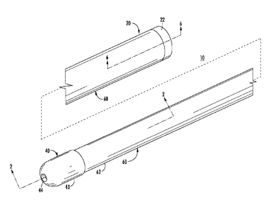
[0026] Referring to FIG. 1, an exemplary fluid dispensing catheter 10 is
described
in accordance with the present disclosure. The catheter 10 includes a proximal
portion 20, a distal portion 30, and an elongate body 60 between the proximal
and
distal portions 20, 30. The proximal portion 20 is configured to be disposed
external
to a patient and is engagable by a clinician to manipulate the distal portion
30. The
distal portion 30 is configured to be inserted through a bronchoscope 390
(FIG. 9)
and/or an extended working channel 96 (FIG. 9) to dispense fluid at a target
site as
described in detail below. The elongate body 60 passes through the
bronchoscope
390 and/or extended working channel 96 to allow a clinician interfacing with
the
proximal portion 20 to dispense fluid from the distal portion 30 in a
controlled
manner.
[0027] With reference to FIG. 2, the elongate body 60 is formed from an
outer
member 62 having an outside surface 62a, an inside surface 62b, and an inner
member
64 that defines a passage 66. The inner member 64 is flexible and configured
to keep
the passage 66 open such that the inner member 64 allows the elongate body 60
to
bend, flex, and/or stretch while preventing the passage 66 from collapsing.
The inner
member 64 is disposed within and in substantial contact with the inside
surface 62b of
the outer member 62. As shown, the outer member 62 formed from a plastic
material
and the inner member 64 is a stainless steel coil disposed within the outer
member 62.
It is envisioned that the inner member 64 can be disposed between the outside
and
inside surfaces 62a, 62b of the outer member 62. Additionally or
alternatively, the
inner member 64 can be formed from a stainless steel coil and the outer member
62
can be formed from a coating applied over the stainless steel coil to
substantially seal
the coil. It is also envisioned that the elongate body 60 can include the
inner member
64 without the outer member 66.
6
CA 2966160 2017-05-04
[0028] Referring now to FIGS. 2-4, the distal portion 30 includes a tip 40
and a
plug 50. The tip 40 includes a cap 42 and an inner wall 46. The cap 42 and the
inner
wall 46 define a channel 43 therebetween. As shown, the channel 43 is a
stepped
annular channel with a large dimension proximal portion 43a and a small
diameter
distal portion 43b; however, it is contemplated that the channel 43 can have a
constant
dimension. The tip 40 is disposed over a distal end 63b of the outer member 62
with
the distal end 63b captured within the channel 43 such that the tip 40 is
secured to the
distal end 63b. When the distal end 63b of is captured within the channel 43,
the
inner wall 46 is disposed within the outer member 62. The inner wall 46
defines a tip
passage 48 that is in communication with the passage 66. The cap 42 defines a
tip
opening 44 that is in communication with the tip passage 48. The tip 40 has an
arcuate distal end portion such that the tip 40, and the catheter 10, can be
atraumatically advanced through a bronchoscope, extended working channel,
and/or
body lumen.
[0029] With additional reference to FIG. 5, the plug 50 includes a proximal
cylinder section 52 disposed within the passage 66 and a distal cylinder
section 54
disposed within the tip passage 48 of the inner wall 46. The plug 50 partially
occludes the passage 66 and configured to restrict flow of fluid from the
passage 66,
through the tip passage 48, and out of the tip opening 44. The plug 50 also
includes a
flat 56 that defines a plane parallel to and offset from a longitudinal axis
of the plug
50 and extends a length of the plug 50. It is envisioned that the flat 56 may
extend the
entire length of the proximal cylinder section 52 and only a portion of the
distal
cylinder section 54. The proximal cylinder section 52 has a diameter
substantially
equal to a diameter of the passage 66 with the flat 56 defining a gap 57 with
the inner
member 64 such that fluid flow from the passage 66 is restricted to flow
through the
7
CA 2966160 2017-05-04
gap 57. The proximal cylinder section 52 can be welded (e.g., laser welded) to
the
inner member 64. It will be appreciated that when the proximal cylinder
section 52 is
welded to the inner member 64, areas adjacent the flat 56 are not welded to
maintain
the dimension of the gap 57.
[0030] Referring now to FIG. 6, the proximal portion 20 of the catheter 10
includes a cover 22 that seals the passage 66. The cover 22 can include a
septum 24
that is configured to seal about a syringe 500 (FIG. 9) inserted through the
septum 24.
[0031] Prior to use, the catheter 10 is filled or loaded with fluid to be
delivered to
target tissue. The fluid can be a therapeutic fluid, a visual marker fluid, an
electromagnetic marker fluid, a fluoroscopic marker fluid, etc. To fill the
catheter 10,
the syringe 500 is filled with a desired fluid. The filled syringe 500 is then
inserted
through the septum 24 of the cover 22 and emptied into the passage 66. The
fluid
flows through the passage to the distal portion 30 of the catheter 10. The
fluid may
cover the gap 57 such that the passage 66 is sealed and the fluid is retained
within the
passage 66. The syringe 500 can be used to partially or entirely fill the
passage 66.
[0032] Alternatively, the catheter 10 can be filled by inserting an empty
syringe
500 through the septum 24 with the tip opening 44 disposed within the desired
fluid.
With the tip opening 44 in the desired fluid, the syringe 500 can be drawn to
create a
vacuum within the passage 66 to draw the desired fluid into the passage 66.
[0033] With reference to FIGS. 7 and 8, the proximal portion 22 of the
catheter 10
can include other structures for sealing the passage 66, filling the passage
66 with a
desired fluid, and dispensing the desired fluid from the passage 66 in a
controlled
manner. For example, with reference to FIG. 7, the proximal portion 22 can
include a
cover 122 including a Luer connector 124 for sealingly attaching a syringe to
the
8
CA 2966160 2017-05-04
cover 122. The cover 122 functions substantially similar to the cover 22 and
will not
be described in detail for reasons of brevity. Alternatively, referring to
FIG. 8, the
proximal portion 20 can include a cover 222 having a plunger 224 having a disc
226
disposed within the passage 66, a handle 228, and a shaft 227 interconnecting
the disc
226 and the handle 228. As the plunger 224 is drawn proximally within the
passage
66, a vacuum is formed within the passage 66 to draw fluid into the distal
portion 30
of the catheter 10 and when the plunger 66 is extended distally within the
passage 66,
pressure is increased within the passage 66 such that fluid is expelled from
the
passage 66 in a similar manner to the syringe detailed above.
[0034] With reference to FIG. 9, an electromagnetic navigation (EMN) system
400 is provided in accordance with the present disclosure to position the tip
40 (FIG.
1) of the filled catheter 10 adjacent target tissue. FIG. 9 also depicts the
fluid
dispensing catheter 10 for use with the EMN system 400. One such EMN system is
the ELECTROMAGNETIC NAVIGATION BRONCHOSCOPY system currently
sold by Covidien LP. Among other tasks that may be performed using the EMN
system 400 are planning a pathway to target tissue, navigating a catheter
guide
assembly to the target tissue, deploying an instrument adjacent or into the
target tissue
to treat or capture the target tissue, digitally marking the location of the
target tissue in
a data file related to the planned pathway, and placing one or more echogenic
markers
at or around the target tissue.
[0035] The EMN system 400 generally includes an operating table 410
configured
to support a patient; a bronchoscope 390 configured for insertion through the
patient's
mouth and/or nose into the patient's airways; a tracking system 470 including
a
tracking module 472, a plurality of reference sensors 474, and an
electromagnetic
9
field generator 476; and a workstation 480 including software and/or hardware
used to
facilitate pathway planning, identification of target tissue, navigation to
target tissue,
and digitally marking the biopsy location.
[0036] The EMN system 400 is used to position an extended working
channel
(EWC) 96 adjacent target tissue. The EMN system 400 may include a locatable
guide
(LG) catheter (not shown) to position the EWC 96. An example of a similar
catheter
guide assembly is currently marketed and sold by Covidien LP under the name
EDGETM Procedure Kits. For a more detailed description of the use of the
catheter
guide assembly reference is made to commonly-owned U.S. Patent Publication
2016/0000302,
Alternatively, the tip 40 of the catheter 10 can include a sensor 49 (FIG. 2),
visible to
the EMN system 400, that can be used to position the EWC 96 adjacent target
tissue.
[0037] With the EWC 96 positioned adjacent target tissue, the tip 40 of
the
catheter 10 is passed through the EWC 96 until the tip 40 extends from the EWC
96.
Fluoroscopy can be used to confirm the location of the tip 40. With the tip 40
extended from the EWC 96, a syringe 500 filled with a fluid (e.g., saline,
oxygen, air,
therapeutic fluid, marking fluid, etc.) is inserted through the cover 22. The
syringe
500 is then extended to increase pressure within the passage 66 of the
catheter 10. As
the pressure within the passage 66 is increased, the desired fluid in the
distal portion
30 of the catheter 10 flows through the gap 57 and out the tip opening 44 of
the
catheter 10. The small size of the gap 57 controls the rate at which the
desired fluid is
dispensed from the tip opening 44. The amount of desired fluid dispensed can
be
determined by the amount of fluid expelled from the syringe 500. For example,
when
the passage 66 is filled with a substantially uncompressible fluid and the
syringe 500
CA 2966160 2018-08-24
CA 2966160 2017-05-04
is filled with saline or a similar uncompressible fluid, the amount of fluid
dispensed
will be substantially equal to the amount of fluid expelled from the syringe
500.
[0038] While the use of the catheter 10 is detailed herein for use in the
airway of a
patient, it is contemplated that the catheter 10 may be used in a variety of
surgical
procedures utilizing elongated surgical instruments with extended working
channels.
For example, the catheter 10 may be used during various endovascular
procedures
such as cardiac interventions, general vascular interventional procedures,
cerebral
interventions, etc. These procedures may include, but are not limited to,
balloon
dilations, stent placements, percutaneous valve replacement, percutaneous
valve
repair, pacing lead placement, cardiac ablation procedures, and electrical
mapping
procedures.
[0039] While several embodiments of the disclosure have been shown in the
drawings, it is not intended that the disclosure be limited thereto, as it is
intended that
the disclosure be as broad in scope as the art will allow and that the
specification be
read likewise. Any combination of the above embodiments is also envisioned and
is
within the scope of the appended claims. Therefore, the above description
should not
be construed as limiting, but merely as exemplifications of particular
embodiments.
Those skilled in the art will envision other modifications within the scope
and spirit of
the claims appended hereto.
11