Note: Descriptions are shown in the official language in which they were submitted.
SEISMIC ACQUISITION METHOD AND APPARATUS
[0ool]
STATEMENT REGARDING FEDERALLY SPONSORED
RESEARCH OR DEVELOPMENT
[0002] Not applicable.
BACKGROUND
[0003] The presently disclosed invention pertains to seismic surveying and,
more particularly, to a technique for low-frequency, seismic acquisition.
[0004] Seismic surveying is the practice of probing subterranean formations in
the Earth using sound waves. This includes imparting acoustic, or sound, waves
into
a natural environment so that they enter the earth and travel through the
subterranean geological formations of interest. During their travels through
the
formations, certain features of the formations will return waves back to the
surface
where they are recorded.
[0005] The recorded returning wave energy is then studied to ascertain
information about those formations. The seismic data derived from the recorded
waves are processed to, for example, image the subterranean formations of
interest.
Frequently, the images are used to model the subterranean formations. For
example, models known as "subsurface attribute models" are frequently
developed
to study the subterranean formations. The images, and models derived from
them,
can help identify subsurface resources. Most notably, these resources may
include
fluid hydrocarbons such as petroleum and natural gas. The techniques may be
applied to the location of other kinds of resources as well.
[0006] One type of seismic survey is the "marine" seismic survey. The term
"marine" only indicates that the survey occurs in or on the water. It does not
necessarily imply that the survey is occurring in a saltwater environment.
While a
marine seismic survey may occur in a saltwater environment such as the ocean,
it
1
Date Recue/Date Received 2021-04-20
CA 02966931 2017-05-04
WO 2016/089892
PCT/US2015/063219
may also occur in brackish waters such as are found in bays, estuaries, and
tidal
swamps. They may even be conducted in wholly fresh waters such as are found in
lakes, marshes, and bogs.
[0007] Another relatively recent development in seismic acquisition is "low-
frequency" acquisition. Seismic surveying historically has used frequencies in
the
range of 6-80 Hz for seismic signals because of their suitability in light of
technical
challenges inherent in seismic surveying. The term "low frequencies" is
understood
within this historical context as frequencies below which getting sufficient
signal to
noise with conventional sources rapidly becomes more difficult as the
frequency
decreases, i.e. below about 6-8 Hz.
[0008] The use of low frequencies for imaging with marine seismic data has
proven challenging for frequencies below about 6 Hz, particularly for
frequencies
below about 4 Hz. The challenge is twofold: at lower frequencies the naturally
occurring seismic background noise of the Earth gets progressively stronger,
and
conventional broadband sources such as airguns get progressively weaker. As a
result, the signal-to-noise of deepwater marine seismic data can decline at
over 30
dB per octave for frequencies below 4 Hz.
[0009] Thus, while there may be many suitable techniques for seismic imaging
in general and for generating subsurface attribute models in particular, the
need for
increased effective signal-to-noise at low frequencies in the acquisition of
seismic
data continues to drive innovation in the art. In particular, among other
things, there
is a need for acquisition and processing techniques that enhance acquisition
and use
of low-frequency seismic data at lower frequencies. The art is therefore
receptive to
improvements or at least alternative means, methods and configurations that
might
further the efforts at improvement.
BRIEF DESCRIPTION OF THE DRAWINGS
[0010] The accompanying drawings, which are incorporated in and constitute
a part of this specification, illustrate embodiments of the invention and
together with
the description, serve to explain the principles of the invention. In the
figures:
[0011] Figure 1 depicts a seismic survey area within an area of interest in
which a low-frequency seismic survey designed according to the technique
disclosed
herein may be conducted;
2
CA 02966931 2017-05-04
WO 2016/089892
PCT/1JS2015/063219
[0012] Figure 2 illustrates a computer-implemented method in accordance
with one aspect of the presently disclosed technique.
[0013] Figure 3 shows selected portions of the hardware and software
architecture of a computing apparatus such as may be employed in some aspects
of
the presently disclosed technique.
[0014] Figure 4 illustrates one particular embodiment in which the technique
first illustrated in Figure 2 forms one part of a larger process.
[0015] Figure 5 conceptually depicts the acquisition of the preliminary data
set
in the embodiment of Figure 4.
[0016] Figure 6 illustrates an exemplary receiver acquisition grid such as the
one used in the acquisition of Figure 5.
[0017] Figure 7 illustrates one particular embodiment of the computing
apparatus of Figure 3 as used in the embodiment of Figure 4 and which is, more
particularly, a computing system on which some aspects of the present
invention
may be practiced in some embodiments.
[0018] Figure 8 depicts an exemplary survey design as might be constructed
in some embodiments of the invention.
[0019] Figure 9 conceptually illustrates a low-frequency, marine seismic
survey conducted in accordance with the survey design of Figure 8.
[0020] Figure 10 depicts a shot gather that approximates one which would
result from the low-frequency, marine survey of Figure 9.
[0021] Figure 11 illustrates another embodiment alternative to that in Figure
4.
[0022] Figure 12 depicts the attenuation of the 3x3 Chebychev arrays
depicted in Figure 8.
[0023] Figure 13A-Figure 13B conceptually depicts one particular acquisition
that may be used in the embodiment of Figure 11.
[0024] Figure 14 schematically depicts signal versus noise for ocean-bottom
data from the deep water Gulf of Mexico
[0025] Figure 15 schematically depicts a "Radar" analysis for ocean-bottom
data from the deep water Gulf of Mexico.
[0026] Figure 16-Figure 17 graphically illustrates one particular embodiment
of
a full-waveform inversion technique as may be practiced in some aspects of the
presently disclosed technique.
3
CA 02966931 2017-05-04
WO 2016/089892
PCT/US2015/063219
[0027] Figure 18 presents selected hardware and software aspects of one
particular embodiment of a computing apparatus such as may be used to
implement
the full-waveform inversion technique of Figure 16- Figure 17.
DESCRIPTION OF THE EMBODIMENTS
[0028] The presently disclosed marine seismic acquisition technique employs
a receiver array and a processing methodology that are designed to attenuate
the
naturally occurring seismic background noise recorded along with the seismic
data
during the acquisition. The approach leverages the knowledge that naturally
occurring seismic background noise moves with a slower phase velocity than the
seismic signals used for imaging and inversion and, in some embodiments, may
arrive from particular preferred directions. The disclosed technique comprises
two
steps: 1) determining from the naturally occurring seismic background noise in
the
preliminary seismic data a range of phase velocities and amplitudes that
contain
primarily noise and the degree to which that noise needs to be attenuated, and
2)
designing an acquisition and processing method to attenuate that noise
relative to
the desired signal. Some embodiments of the disclosed technique also employ
the
arrival direction, or azimuth, of the noise because, where available, its use
can
sometimes prove advantageous.
[0029] What constitutes "primarily noise" and the degree of noise attenuation
required will vary from embodiment to embodiment depending on implementation
specific details. It is well known in the art that all seismic data contains
noise and
that the magnitude of this noise is measured by the "signal to noise" ratio,
or the "SIN
ratio". In general, the S/N ratio in any seismic data set must be high enough
such
that subsequent processing yields usable results for the purpose intended by
the
processing. Accordingly, the required S/N ratio and thus the required noise
attenuation will vary depending on the processing employed and the use to
which
the processing results will be put. What constitutes "primarily noise" is
therefore not
readily amenable to objective quantification because of implementation
specific
variation. For present purposes, objectionable noise is that which is at an
amplitude
where it seriously degrades the ability to use the signal overlapping with it.
[0030] For example, one principal motivation for acquiring low frequencies is
for the purpose of full-waveform inversion ("FWI"). FWI is an iterative
optimization
4
CA 02966931 2017-05-04
WO 2016/089892
PCT/US2015/063219
process that attempts to find an earth model that explains all of the seismic
information recorded at the receivers. In an embodiment, FWI produces a three-
dimensional volume giving an estimated subsurface attribute at each
illuminated
point within the earth. In embodiments, the subsurface attribute may include,
but is
not limited to, P-wave velocity, S-wave velocity, density, anisotropy
parameters,
elastic constants, attenuation parameters, or other subsurface wave
velocities.
[0031] One popular FWI algorithm is frequency-domain FWI, in particular
phase-only frequency-domain FWI, in which case only the phase of the data, and
not
its amplitude, are used for the inversion. To determine the impact of ambient
noise
on phase-only frequency-domain FWI, we first model seismic acquisition without
noise, and calculate a phase for each source-receiver pair. We then add to the
model results appropriately scaled measurements of ambient noise from the
field,
and again calculate a phase for each source-receiver pair. The difference
between
these indicates the phase error attributable to the ambient noise.
[0032] Modeling shows phase-only frequency-domain FWI results are not
significantly degraded if the RMS phase errors introduced by the noise are
less than
about 20 degrees. We then must determine how much noise attenuation is
required
to reduce the RMS phase errors below this threshold. So, continuing this
example, a
modeled 1.5 Hz monochromatic signal lasting 1 minute processed against a
background of measured noise produces a phase error of 2 degrees at a distance
of
1 km, 10 degrees at 5 km, 20 degrees at 10 km, 41 degrees at 20 km, and 57
degrees at 30 km. Thus at 10 km the S/N (of about 2.5) is just adequate, but
if we
require offsets of 30 km then we must attenuate the noise relative to the
signal at 1.5
Hz by about a factor of 30 / 10 = 3, or about 10 dB. Thus, in these particular
embodiments with these particular parameters, data that are "primarily noise"
are
data whose SIN ?.-2.5. Those skilled in the art having the benefit of this
disclosure
will be able to perform similar calculations for other acquisition scenarios.
[0033] Receiver arrays to attenuate slow-moving noise are a conventional
technique for land seismic surveys. Land receiver arrays typically contain a
large
number of elements. Such large arrays would be impractical for use with ocean-
bottom node surveys. Consequently, conventional wisdom within the art is that
such
arrays are not useful and are not used in marine surveys.
[0034] Frequency-domain FWI requires data at only a small number of
discrete frequencies to produce a useful result. Of this small number of
discrete
CA 02966931 2017-05-04
WO 2016/089892
PCT/US2015/063219
frequencies, typically only the lowest is sufficiently impacted by ambient
noise to
require a receiver array to suppress it. Thus, for an ocean-bottom node survey
performed for the purposes of frequency-domain FWI, we have discovered that
one
can optimize the array design for that lowest frequency. In contrast to
conventional
broadband array design, this narrowband application allows dramatic reduction
in the
number of elements required, allowing recordation of usable data at lower
frequencies than would otherwise be possible. The lower the usable frequency
in
the data, the larger the velocity anomaly that FWI can successfully resolve.
[0035] Although the method is described in terms of its particular
applicability
to data acquired for the purpose of processing with frequency-domain RN!,
those of
ordinary skill in the art will recognize that the techniques described herein
are also
amenable to other processing techniques, such as tomography or imaging via
migration.
[0036] Reference will now be made in detail to the present embodiments
(exemplary embodiments) of the invention, examples of which are illustrated in
the
accompanying drawings. Wherever possible, the same reference numbers will be
used throughout the drawings to refer to the same or like parts.
[0037] Turning now to Figure 1, the marine seismic survey is to be conducted
in a survey area 100 located in an area of interest 105. The area 105 is of
interest
because of its potential for the production of a resource of interest e.g.,
fluid
hydrocarbons. The industry spends a great deal of effort locating,
identifying, and
acquiring rights to areas of interest such as the area of interest 105. The
same is
true for the selection of the survey area 100 within the area of interest 105.
Accordingly, the means and methods by which this is done are well known in the
art
and so will not be further discussed so as not to obscure the invention.
[0038] The survey area 100, and the area of interest 105 in general,
experience naturally occurring seismic background noise 110. Those in the art
will
appreciate that the naturally occurring seismic background noise 110 is
typically
more diffuse than one might infer from the graphic element used to represent
it in
Figure 1. The
naturally occurring seismic background noise 110 can be
characterized by attributes such as phase velocity, amplitude, azimuth, etc.,
and
generally will not vary greatly in those attributes within an area of interest
105, or will
vary with position in a smooth and predictable manner.
6
CA 02966931 2017-05-04
WO 2016/089892
PCT/US2015/063219
[0039] Those in the art will also appreciate that the scale of both the survey
area 100 and the area of interest 105 may vary greatly depending on the
particular
use. This is true in the sense of the relative sizes. The survey area 100 may
in
some embodiments be coterminous or nearly coterminous with the area of
interest
105 while in some embodiments it may be only a very small part. It is also
true of
their sizes in an absolute sense. They may be several tens of square miles or
several hundreds of square miles, for example.
[0040] The presently disclosed technique includes a computer-implemented
method 200, illustrated in Figure 2, for designing a low-frequency marine
seismic
survey. In this context, "low-frequency" means frequencies less than about 6-8
Hz.
Some embodiments will be below about 4 Hz, some of which may employ
frequencies as low as about 2 Hz, or about 1.5 Hz, or about 0.5 Hz. The term
"about" is a recognition that in acquisition seismic sources may come out of
calibration or be poorly calibrated, simultaneously radiate at additional
frequencies
(for example from harmonics or from noise from a compressor), or that their
signals
can drift or in other ways deviate from what is desired. Thus, the term
"about"
means that the actual frequency is within the operational error acceptable to
those in
the art relative to the desired frequency of acquisition.
[0041] Returning now to Figure 1-Figure 2, the survey will be conducted by
towing one or more low-frequency, marine seismic sources (not shown) through
the
water column 115 with a receiver grid (not shown) positioned on the seabed
120.
Since it is known that the survey will be conducted using low seismic
frequencies, it
is also known that the naturally occurring seismic background noise 110 may
create
issues in the resultant data set. Accordingly, the method 200 attempts to
mitigate
those issues in the survey design by designing a receiver array that will
suppress the
naturally occurring seismic background noise 110 in the seismic data collected
in the
survey.
[0042] To design a receiver array to attenuate naturally occurring seismic
background noise implies an a priori knowledge of that noise. This knowledge
may
be gleaned from previously acquired seismic data which, for present purposes
shall
be referred to as the "preliminary seismic data set." Thus, the method 200
first
determines (at 210) from the naturally occurring seismic background noise in
the
preliminary seismic data a range of phase velocities over which the noise is
at an
7
CA 02966931 2017-05-04
WO 2016/089892
PCT/US2015/063219
amplitude relative to the desirable signal such that the noise requires
attenuation,
and the degree to which that noise needs to be attenuated.
[0043] The method 200 admits wide variation as to the origin of the
preliminary data. It may be a legacy of a previous, conventional acquisition,
i.e.,
"legacy" data. Or it may be acquired in conventional fashion for the very
purpose of
implementing the present technique. It may also be from a low-frequency
acquisition
in some embodiments. The manner and time frame in which the preliminary
seismic
data are acquired is not material to the practice of the technique. Regardless
of
these types of considerations, however, the receiver grid through which the
preliminary seismic data are acquired should provide a sensor density
sufficient that
the naturally occurring seismic background noise 110 is not aliased. One
particular
embodiment achieves such a density with a sensor spacing of 450 m.
[0044] The preliminary data should be acquired in the survey area 100 or, if
not, within the area of interest 105. The naturally occurring seismic
background
noise 110 can be directly determined if the preliminary seismic data are
acquired
within the survey area 100. However, this is not necessarily required, and the
naturally occurring seismic background noise 110 may be estimated from seismic
data acquired within the area of interest 105. As those in the art will
appreciate, the
naturally occurring seismic background noise 110 will vary depending on
location.
Thus, if the preliminary data are acquired in the area of interest 105, the
naturally
occurring seismic background noise 110 is estimated rather than directly
determined.
[0045] This implicitly limits the area of interest 105 to an area in which any
acquired seismic data contains a naturally occurring seismic background noise
110
that is at least similar to that found in the survey area 100. Since the
naturally
occurring seismic background noise 110 varies depending on location, so too
does
the area of interest 105. One particular embodiment considers the area of
interest
105 to be limited to the basin in which the survey area 100 is contained.
[0046] The frequency range and amplitudes of the naturally occurring seismic
background noise will generally vary with the season and the sea state. This
variation can also be measured or estimated, and may be used to improve
planning
estimates of background noise levels. For example, if the noise levels are
measured
in summer, but the acquisition will be performed in winter, the noise level
estimates
from the summer may be seasonally adjusted to provide a better estimate of
their
likely winter levels.
8
CA 02966931 2017-05-04
WO 2016/089892
PCT/US2015/063219
[0047] The preliminary seismic data should also be amenable to a "box wave"
analysis. One suitable box wave analysis is described in the context of a land
survey
in Chapter 11 of Carbonate Seismology, Volume 6, Palaz et al. eds. (1997). In
this
context, the acoustic waves from which seismic data are recorded are
relatively
weaker, but with a relatively faster phase velocity, than the naturally
occurring
seismic background noise 110. This is a classic "box wave" scenario,
particularly
when the naturally occurring seismic background noise 110 arrives from a known
range of azimuths. The method 200 therefore seeks to mitigate or suppress the
naturally occurring seismic background noise 110 through a receiver array
designed
(at 220) to attenuate the undesired slower wave modes but pass waves with
faster
phase velocities.
[0048] Accordingly, the method 200 then designs (at 220) a low-frequency
seismic survey of the survey area. This includes both an ocean bottom seismic
receiver array (at 230) in which the receivers are positioned so as to filter
the
naturally occurring seismic background noise 110 and a seismic source shooting
plan (at 240).
[0049] Those in the art having the benefit of this disclosure will also
appreciate that the aspect of the presently disclosed technique illustrated in
Figure 2
is computer-implemented. Figure 3 conceptually depicts selected portions of
the
hardware and software architecture of a computing apparatus 300 such as may be
employed in some aspects of the present invention. The computing apparatus 300
includes an electronic processor 303 communicating with storage 306 over a
communication medium 309.
[0050] The electronic processor 303 may be any suitable electronic
processor or processor set known to the art. Those in the art will appreciate
that
some types of processors will be preferred in various embodiments depending on
familiar implementation-specific details. Factors such as processing power,
speed,
cost, and power consumption are commonly encountered in the design process and
will be highly implementation specific.
[0051] Because of their ubiquity in the art, such factors will be easily
reconciled by those skilled in the art having the benefit of this disclosure.
Those in
the art having the benefit of this disclosure will therefore appreciate that
the
electronic processor 303 may theoretically be an electronic micro-controller,
an
electronic controller, an electronic microprocessor, an electronic processor
set, or an
9
CA 02966931 2017-05-04
WO 2016/089892
PCT/US2015/063219
appropriately programmed application specific integrated circuit ("ASIC"),
field
programmable gate array ("FPGA"), or graphical processing units ("GPUs"). Some
embodiments may even use some combination of these processor types.
[0052] However, those in the art will also appreciate that data sets such as
the preliminary seismic data ('PSD") 324 are quite voluminous and that the
processing described herein is computationally intensive. Typical
implementations
for the electronic processor 303 therefore actually constitute multiple
electronic
processor sets spread across multiple computing apparatuses working in
concert.
One such embodiment is discussed below. These considerations also affect the
implementation of the storage 306 and the communication medium 309 similarly.
[0053] The storage 306 may include a hard disk and/or random access
memory ('RAM") and/or removable storage such as a floppy magnetic disk 312 and
an optical disk 315. The storage 306 is encoded with a number of software
components. These components include an operating system ("OS") 318; an
application 321; a data structure comprised of the preliminary seismic data
324; and,
once developed, a low-frequency, marine seismic survey design 327. Some
embodiments may also include a data structure comprised of low-frequency,
marine
seismic data ("LFD") 330. The storage 306 may be distributed across multiple
computing apparatuses as described above.
[0054] As with the electronic processor 303, implementation-specific design
constraints may influence the design of the storage 306 in any particular
embodiment. For example, as noted above, the disclosed technique operates on
voluminous data sets which will typically mitigate for various types of "mass"
storage
such as a redundant array of independent disks ("RAID"). Other types of mass
storage are known to the art and may also be used in addition to or in lieu of
a RAID.
As with the electronic processor 303, these kinds of factors are commonplace
in the
design process and those skilled in the art having the benefit of this
disclosure will be
able to readily balance them in light of their implementation specific design
constraints.
[0055] The electronic processor 303 operates under the control of the OS
318 and executes the application 321 over the communication medium 309. This
process may be initiated automatically, for example upon startup, or upon user
command. User command may be directly through a user interface. To that end,
CA 02966931 2017-05-04
WO 2016/089892
PCT/US2015/063219
the computing system 300 of the illustrated embodiment also employs a user
interface 342.
[0056] The user interface 342 includes user interface software ("UIS") 345
and a display 340. It may also include peripheral input/output ('I/O") devices
such as
a keypad or keyboard 350, a mouse 355, or a joystick 360. These will be
implementation-specific details that are not germane to the presently
disclosed
technique. For example, some embodiments may forego peripheral I/O devices if
the
display 340 includes a touch screen. Accordingly, the presently disclosed
technique
admits wide variation in this aspect of the computing system 300 and any
conventional implementation known to the art may be used.
[0057] Furthermore, there is no requirement that the functionality of the
computing system 300 described above be implemented as disclosed. For example,
the application 321 may be implemented in some other kind of software
component,
such as a daemon or utility. The functionality of the application 321 need not
be
aggregated into a single component and may be distributed across two or more
components. Similarly, the data structures for the preliminary seismic data
324 and
low-frequency, marine seismic data 330 may be implemented using any suitable
data structure known to the art.
[0058] As with the electronic processor 303 and the storage 306, the
implementation of the communications medium 309 will vary with the
implementation. If the computing system 300 is deployed on a single computing
apparatus, the communications medium 309 may be, for example, the bus system
of
that single computing apparatus. Or, if the computing system 300 is
implemented
across a plurality of networked computing apparatuses, then the communications
medium 309 may include a wired or wireless link between the computing
apparatuses. Thus, the implementation of the communications medium 309 will be
highly dependent on the particular embodiment in ways that will be apparent to
those
skilled in the art having the benefit of this disclosure.
[0059] Note that the various sets of data 324, 330 discussed herein are
collections of ordered data representative of a tangible, real world, natural
environment. This
includes tangible, real world objects that comprise that
environment, although in some cases it may include data characterizing a
signal.
For example, seismic data are information characterizing the subterranean
formations from which it is generated. Similarly, the survey plan 327 also
represents
11
CA 02966931 2017-05-04
WO 2016/089892
PCT/US2015/063219
a tangible, real world environment, namely the placement and operation of
survey
components during a seismic survey.
[0060] The seismic data 324, 330 and the survey plan 327 may, or may not
be, rendered for human perception either by electronic display or by hard copy
reduction depending upon the particular embodiment being implemented. The
disclosed technique is indifferent as to whether such a rendering occurs. The
seismic data 324, 330 and the survey plan 327 in the illustrated embodiments
are
not rendered but are instead analyzed without rendering.
[0061] Some portions of the detailed descriptions herein are therefore
presented in terms of a software implemented process involving symbolic
representations of operations on data bits within a memory in a computing
system or
a computing device. These descriptions and representations are the means used
by
those in the art to most effectively convey the substance of their work to
others
skilled in the art. The process and operation require physical manipulations
of
physical quantities that will physically transform the particular machine or
system on
which the manipulations are performed or on which the results are stored.
Usually,
though not necessarily, these quantities take the form of electrical,
magnetic, or
optical signals capable of being stored, transferred, combined, compared, and
otherwise manipulated. It has proven convenient at times, principally for
reasons of
common usage, to refer to these signals as bits, values, elements, symbols,
characters, terms, numbers, or the like.
[0062] It should be borne in mind, however, that all of these and similar
terms are to be associated with the appropriate physical quantities and are
merely
convenient labels applied to these quantities. Unless specifically stated or
otherwise
as may be apparent, throughout the present disclosure, these descriptions
refer to
the action and processes of an electronic device, that manipulates and
transforms
data represented as physical (electronic, magnetic, or optical) quantities
within some
electronic device's storage into other data similarly represented as physical
quantities within the storage, or in transmission or display devices.
Exemplary of the
terms denoting such a description are, without limitation, the terms
"processing,"
"computing," ''calculating," "determining," "displaying," and the like.
[0063] Furthermore, the execution of the software's functionality transforms
the computing apparatus on which it is performed. For example, acquisition of
data
will physically alter the content of the storage, as will subsequent
processing of that
12
CA 02966931 2017-05-04
WO 2016/089892
PCT/US2015/063219
data. The physical alteration is a "physical transformation" in that it
changes the
physical state of the storage for the computing apparatus.
[0064] Note also that the software implemented aspects of the invention are
typically encoded on some form of program storage medium or, alternatively,
implemented over some type of transmission medium. The program storage
medium may be magnetic (e.g., a floppy disk or a hard drive) or optical (e.g.,
a
compact disk read only memory, or "CD ROM"), or charge based (e.g., a flash
memory) and may be read only or random access. Similarly, the transmission
medium may be twisted wire pairs, coaxial cable, optical fiber, or some other
suitable
transmission medium known to the art. The invention is not limited by these
aspects
of any given implementation.
[0065] Those in the art will appreciate that the technique described above
may be a part of a larger process stretching from acquisition of the
preliminary
seismic data 324 through the conduct of the low-frequency, marine seismic
survey
for which the survey plan 327 is developed. To further an understanding of the
presently disclosed technique, its role in such a larger process will now be
disclosed
in one particular embodiment.
[0066] Turning now to Figure 4, this particular embodiment 400 begins with
the acquisition (at 410) of the preliminary seismic data. This seismic data
are
"preliminary" only in the sense of its role in the development of a subsequent
low-
frequency, marine seismic survey. It may have at one time been the object in
and of
itself in the conduct of the survey in which it was acquired. In that context,
it may not
have been "preliminary" at all. In the present context, it is considered
"preliminary"
because it is not the seismic data collected during the low-frequency marine
seismic
survey it will be used to design.
[0067] Referring now to Figure 5, the acquisition 410 is performed in a
conventional ocean bottom survey in this particular case. A tow vessel 500
tows one
or more conventional sources 503 that may be, for example, airguns or sweep
sources such as are known in the art. on the water's surface 506. The
source(s) 503
impart one or more seismic signals 509 into the water column 115 to penetrate
the
seabed 120 and where they interact with subterranean structures 512, causing a
portion of the seismic energy 515 to return toward the surface.
[0068] The returning seismic energy 515 then propagates back to the
receiver grid 518 on the seabed 120. The receiver grid 518 includes a
plurality of
13
CA 02966931 2017-05-04
WO 2016/089892
PCT/US2015/063219
receivers 521 (only one indicated). Figure 6, adapted from Dellinger, J., and
J.
Ehlers, "Low Frequencies With a 'dense' OBS Array: The Atlantis Green-Canyon
Earthquake Dataset.", in 2007 SEC Annual Meeting abstracts, Society of
Exploration
Geophysicists (2007), maps the receiver positions in one particular
implementation
of the receiver grid 518, each numbered circle 600 (only one indicated)
representing
a receiver 521. Note the receiver density (i.e., 5 450m), which will mean that
the
naturally occurring seismic background noise 110 will be unaliased. The
receivers
521 themselves could be hydrophones, geophones, or multicomponent depending
on the implementation. The returning seismic energy 515 is detected by the
receivers 521 and recorded as seismic data. Recorded data that contain energy
from known manmade seismic sources 503 are called "active" seismic data.
[0069] The receivers 521 also record seismic data due to natural sources, in
particular they record when there are no nearby conventional active sources
503
operating. Data recorded in the absence of known manmade sources are called
"passive" seismic data. In this particular embodiment, the active and passive
seismic data recorded by the receivers 521 become the "preliminary seismic
data".
The recorded preliminary seismic data are then communicated to a computing
facility
524. This communication may be, for example, by hard copy on a magnetic tape
527 or by transmission via a satellite 530.
[0070] The computing facility 524 houses a computing system by which the
preliminary seismic data are processed as described above to design the low-
frequency seismic survey. A portion of an exemplary computing system 700 is
shown in Figure 7. The computing system 700 is networked, but there is no
requirement that the computing system 700 be networked. Alternative
embodiments
may employ, for instance, a peer-to-peer architecture or some hybrid of a peer-
to-
peer and client/server architecture. The size and geographic scope of the
computing
system 700 is not material to the practice of the invention. The size and
scope may
range anywhere from just a few machines of a Local Area Network ("LAN")
located in
the same room to many hundreds or thousands of machines globally distributed
in
an enterprise computing system.
[0071] The computing system 700 comprises, in the illustrated portion, a
server 710, a mass storage device 720, and a workstation 730. Each of these
components may be implemented in their hardware in conventional fashion.
Alternative embodiments may also vary in the computing apparatuses used to
14
CA 02966931 2017-05-04
WO 2016/089892
PCT/US2015/063219
implement the computing system 700. Those in the art will furthermore
appreciate
that the computing system 700, and even that portion of it that is shown, will
be
much more complex. However, such detail is conventional and shall not be shown
or discussed to avoid obscuring the subject matter claimed below.
[0072] In Figure 7, the application 321 is shown residing on the server 710
while the preliminary seismic data 324, marine seismic survey plan 327, and
the low-
frequency seismic data 330 are shown residing in the mass storage 720. While
this
is one way to locate the various software components, the technique is not
dependent upon such an arrangement. Although performance concerns may
mitigate for certain locations in particular embodiments, the situs of the
software
components is otherwise immaterial.
[0073] Returning to Figure 4, the preliminary seismic data 324 are analyzed
to determine (at 420) from the naturally occurring seismic background noise
110 in
the survey area 100 in the preliminary seismic data a range of phase
velocities over
which the noise is at an amplitude relative to the desirable signal such that
the noise
requires attenuation, and the degree to which that noise needs to be
attenuated.
The azimuth of arrival for the naturally occurring seismic background noise
110 is
also ascertained (at 430). This can be done by performing what is known in the
art
as a "radar" analysis of the preliminary seismic data 324. The radar analysis
can be
performed by the application 321, shown in Figure 7, for example, responsive
to
input by the user 740.
[0074] Figures 14 and 15 show an example of how one might determine the
phase velocities (at 420) and the azimuths (at 430). To determine the
amplitude of
the background noise, calibrated power spectra are plotted for time windows
extracted from both the active and passive preliminary seismic data. In some
embodiments, the active and passive preliminary seismic data may be extracted
from different seismic surveys. Figure 14 shows a representation of typical
active
and passive power spectra for ocean-bottom seismic data from the deep water
Gulf
of Mexico. In the active-data time window shown in Figure 14, the sources were
conventional airguns located about 2.5km from the receiver. Over the frequency
range of interest (0.5 ¨ 6 Hz) the background noise and the energy from
conventional sources can be well approximated as straight lines on a log-log
plot, as
shown here.
[0075] The active-source data may be plotted for a range of source locations,
showing how the amplitude of conventional sources varies with source-receiver
offset, and thus how the signal to noise ratio varies with source-receiver
offset.
Alternatively, the amplitude curve for a known offset may be shifted up and
down to
model the amplitude at other offsets, based on a model of how amplitude should
vary with offset, for example spherical spreading.
[0076] Note that for conventional airgun sources in the deep water Gulf of
Mexico, below 2 Hz the active data closely approximates passive data even for
relatively nearby active sources. Thus an analysis of the amplitude of the
ambient
noise below about 2 Hz can be made even from conventional active data, because
conventional seismic sources produce very little energy in this frequency
range. For
some ocean basins ambient-noise spectra have been published and are freely
available, and this is another possible source of data about ambient noise
levels.
The ambient-noise spectra vary with season and sea state, and this variation
may be
accounted for when estimating what ambient noise levels to design for,
[0077] Modeling of the expected imaging challenge will determine how low a
frequency, with what signal to noise at what maximum source-receiver offset,
is
expected to be required to image the subsurface structures of interest.
Alternatively,
empirical experience with similar imaging challenges in similar basins may be
used
to estimate these.
[0078] The dots labeled "LFS" in Figure 14 indicate a range of possible
single-frequency "humming" sweeps that are available from a controllable low-
frequency source (LFS). Additional information regarding frequency humming
sweeps may be found in U.S. Application Serial No. 13/327,524 and U.S.
Application
Serial No. 61/896,394. Other
types of sweeps, for
example narrowband sweeps of a restricted frequency range over an octave or
less,
could also be used. Note the low-frequency source has greatly reduced
bandwidth
compared to airguns, but can achieve a much higher signal to noise over a
restricted
frequency range. However, as for airguns, the achievable power rapidly
declines as
the frequency decreases, so there is a tradeoff to be optimized between
frequency
and signal to noise.
[0079] The signal achievable from a controllable low-frequency source
performing a particular sweep may be empirically measured, or it may be
estimated
based on considerations such as the size of the device, the water it
displaces, the
16
Date Recue/Date Received 2021-04-20
CA 02966931 2017-05-04
WO 2016/089892
PCT/US2015/063219
force it applies to the water, the estimated spreading and attenuation of the
signal in
the subsurface, etc., or a combination of both. If insufficient source signal
is
expected to be available at the required lowest frequency, then the shortfall
in dB
should be calculated (for example from a plot like Figure 14), to be followed
by an
investigation into how to increase the signal to noise by attenuating the
noise by at
least that amount. One possible solution is to boost the signal by building a
larger
device or employing an array of sources. The alternative solution, described
here, is
to attenuate the noise relative to the signal.
[0080] Figure 15 shows a schematic "radar" plot for pressure data from an
ocean-bottom node grid in the deep water Gulf of Mexico. The polar plot shows
energy across a grid (such as is shown in Figure 6) as a function of phase
slowness
(inverse horizontal phase velocity) and azimuth. Zero phase slowness
(indicating a
wave impinging on all parts of the grid simultaneously) plots in the center.
The outer
rim indicates energy moving at 1000 m/s, energy traveling North-to-South at
that
velocity at the top edge of the plot, West-to-East at that velocity at the
left edge, etc.
[0081] For this example the energy is mostly coming from a range of
azimuths centered on the Southeast, at a range of phase velocities between
about
1600 and 3000 meters per second. The desirable active-source data arrives at
higher velocities which would plot nearer to the center of the plot. The
azimuth,
amplitude, and frequency range of the ambient noise may vary with season and
weather, but the range of velocities is a function of the local geology and
should not
change. Thus by picking a range of phase slownesses to attenuate and the
required
dB noise suppression over that range, we may design an appropriate receiver
array,
as is well known to those skilled in the art of box wave analysis.
[0082] A receiver array is specified by its geometry and the set of weights Ai
applied to the elements of the array (here the elements are indexed by j). One
preferred type of array well known in the art is a "Chebychev array", which
maximizes the minimum attenuation over a specified reject hand. Other types of
arrays with different useful properties are also possible and are known to
those
skilled in the art of array design for surface-wave noise attenuation.
[0083] A radar analysis may also be performed on the active data, to
determine the velocities and azimuths of the energy from an active source, to
ensure
that the array does not also overly attenuate the desirable signal. Active
sources
17
CA 02966931 2017-05-04
WO 2016/089892
PCT/US2015/063219
may also generate undesirable signals such as surface waves and ideally the
array
may also attenuate these.
[0084] Once the naturally occurring seismic background noise 110 and its
azimuth of arrival are ascertained (at 420, 430), the method 400 then designs
(at
220) a low-frequency seismic survey 327 of the survey area 100. This includes
both
an ocean bottom seismic receiver array (at 230) in which the receivers are
positioned so as to filter the naturally occurring seismic background noise
110 and a
seismic source shooting plan (at 240). As described above, the receiver array
is
designed to attenuate the naturally occurring seismic background noise 110,
and the
seismic source shooting plan complements the receiver array design.
[0085] Continuing with this particular specific example, a receiver array
filters
seismic energy by its wavenumber (one over the wavelength of the wave measured
along the recording surface). To determine the minimum and maximum
wavenumber, one determines the minimum and maximum phase velocities to be
attenuated over, and the minimum and maximum frequencies of interest. The
minimum wavenumber is then the minimum frequency divided by the maximum
phase velocity, and the maximum wavenumber is the maximum frequency divided by
the minimum phase velocity.
[0086] For this example the minimum and maximum frequency are both 1.6
Hz, so the minimum wavenumber is 1.6 Hz / 3000 m/s, and the maximum
wavenumber is 1.6 Hz / 1600 m/s. An optimal array has its Nyquist sample
spacing
centered between these minimum and maximum wavenumbers. For this example, if
d is the array spacing then 1/2 d = (1.6 / 3000
+ 1.6 / 1600), and we find d = 652.17
or about 650 meters.
[0087] Figure 12
shows the attenuation of a 3 x 3 Chebychev array for this
example, which achieves a minimum attenuation of about 18 dB over the required
wavenumber interval. Alternative embodiments using other types of arrays are
also
possible, for example the gain over the reject band may be adjusted to match
the
shape of the noise spectrum over that wavenumber window. Other array
configurations are also possible, for example hexagonal arrays 605 (only one
indicated) as illustrated in Figure 6, or the arrays may have different
spacings along
different axes. In embodiments, the node deployment method might preclude
being
able to precisely specify where the nodes land. The array design may be
modified to
take account of the fact that the deployed array may only approximate the
acquisition
18
CA 02966931 2017-05-04
WO 2016/089892
PCT/US2015/063219
design, due to constraints on where nodes may be located or how accurately
they
can be placed.
[0088] The minimum attenuation of a Chebychev array is a function of the
ratio of the minimum and maximum wavenumbers and the number of elements in the
array. Arrays with more elements achieve higher attenuation, but at greater
acquisition expense, as is well known to those skilled in the art of array
design. Note
the design principles exemplified here are the same as for land array design,
for
which these tools and this methodology were originally designed. Land arrays
typically must handle broadband data, so much larger arrays are used in that
case,
typically 12 x 12 at a minimum. For the low-frequency seismic imaging
application of
particular interest, full-waveform inversion, only a small number of separated
discrete
frequencies are required.
[0089] In this example we do not need to design a broadband array because
as shown in Figure 14, the signal to noise rapidly improves with increasing
frequency. At higher frequencies a receiver array to suppress the ambient
noise is
not required, so arrays will only be required at the lowest frequency used in
the
survey. Because we are only attempting to design an array that attenuates
noise at
a single frequency, even a humble 3 x 3 array can provide significant noise
rejection.
[0090] Outside of the frequency band that the array was designed for, it may
not provide much noise rejection. However, noise outside the frequencies of
interest
can easily be suppressed by conventional frequency filtering in the time
domain, so
this is not a problem.
[0091] Once the receiver arrays have been designed, they are incorporated
into the survey design. First the survey is designed in the conventional way
assuming no noise, then each receiver node in the acquisition grid is replaced
with a
small array. Consider,
for example, the marine seismic survey design 800,
conceptually illustrated in Figure 8. The technique disclosed herein does not
necessarily render the marine seismic survey design 800 in a human perceptible
form as was discussed above. Figure 8 is used only to illustrate selected
aspects of
the marine seismic survey design 800 to further an understanding of the
presently
claimed subject matter.
[0092] The marine seismic survey design 800 includes a receiver grid 803
comprised of several receiver lines 806 spaced 4 km apart. In the absence of
ambient noise, a single line of nodes 809 (only one indicated) would be spaced
19
CA 02966931 2017-05-04
WO 2016/089892
PCT/US2015/063219
along this line at a spacing determined by the sampling requirements of the
survey.
(Each node represents a seismic receiver.) This shooting geometry, with shots
that
are densely spaced in one direction and receivers that are densely spaced in
the
orthogonal direction, may be referred to as "sparse 3D acquisition".
[0093] In Figure 8, the shot spacing is dense along the horizontal axis of the
figure, and the receivers are dense along the vertical axis of the figure.
Representative shot locations 810 (only one indicated) are shown on the shot
line
815 spaced at about 150m apart. Here "dense" means "a sample spacing
sufficiently fine to represent the wavefields of interest without aliasing".
By the
Nyquist sampling criterion, "dense" means a sample spacing 1/2 VI F, where F
is
the frequency and V is the horizontal phase velocity of a wavefield of
interest.
"Sparse" is a sample density much less than this, i.e., a sample spacing > -3x
that
for a dense sample spacing.
[0094] In practice the lines need not be exactly orthogonal, but in this case
the inline sample spacing of the deviated line should be multiplied by about
the
cosine of the deviation from orthogonality to maintain the same effective
sampling.
Thus, more shot or receiver points will be required and such a geometry is
less
efficient.
[0095] Other survey designs are possible. In particular, it has been
discovered that full-waveform inversion ("FWI") does not need the same sort of
coverage that is needed for imaging. FWI needs good sampling along each axis
in
either the shot domain or in the receiver domain, but not both. There are
three
fundamental ways to achieve the required sampling. A sparse 3D acquisition
(such
as in Figure 8) achieves the required sampling with orthogonal shot and
receiver
lines, each dense in the inline direction, but coarse in the crossline
direction.
[0096] Alternatively, in sparse receiver acquisition, the shots are areally
dense, in which case the receivers may then be coarsely spaced. This is the
typical
acquisition strategy used at conventional frequencies, because it is much less
expensive to acquire a dense coverage of sources (typically airguns towed
behind a
ship) than a dense coverage of ocean-bottom receivers (which may need to be
manually placed one at a time by a remotely operated vehicle ('ROV)). Figure 6
shows an example of such a receiver grid for a conventional seismic survey.
The
nodes are -450 m apart, which is not dense at conventional seismic
frequencies.
Conventional seismic frequencies are primarily above about 6 Hz. The term
CA 02966931 2017-05-04
WO 2016/089892
PCT/US2015/063219
"primarily" here denotes that some broadband sources (such as airguns) emit
energy
at many frequencies, some of which may be different from what is considered
the
nominal frequency of the signal. So, as recognized by those skilled in the art
having
the benefit of this disclosure, even signals nominally considered above 6 Hz
can be
accompanied by some lesser amounts of energy below 6 Hz. Thus, the signal is
"primarily" above 6 Hz in this context.
[0097] However, this same receiver grid with nodes ¨450 m apart becomes
dense for frequencies below about 1.7 Hz. Thus in some embodiments,
particularly
in a "piggyback survey", where a receiver grid designed for a conventional
survey is
also used for low-frequency acquisition, sparse-shot acquisition may be used
for the
low-frequency acquisition. In sparse-shot acquisition the shots may be
coarsely
spaced, taking advantage of an areally dense receiver grid to achieve the
required
sampling (i.e., the receiver grid is dense along both horizontal axes). Note
that a
"piggyback survey" results in a single acquisition.
[0098] In the present context "coarse" means with spacings much greater
than what is required with conventional frequencies, i.e., frequencies about 6-
8 Hz.
For example, one particular embodiment uses areally dense shots but quite
coarse
node spacings, e.g. a grid with nodes 4 km apart. However, the spacings should
not
be "excessively coarse", i.e. greater than about 10 km apart, which can yield
more
undesirable artifacts.
[0099] These observations might manifest themselves in a variety of
acquisition strategies. For example, one might use a tighter grid of nodes
(such as
the grid in Figure 6) over the central part of the model of interest doing
double duty
for conventional imaging purposes as well. These would then be surrounded by a
much coarser grid of nodes sufficient to acquire ultra-wide offsets for FWI
over the
area of interest. Alternatively, an extensive areal coarse grid of nodes might
be
expensive, because the boat laying the nodes will need to traverse long
distances
between node placements and spend a lot of time traveling. If the survey does
not
require a rich offset distribution, then a more closely spaced line of nodes
at one or
more offsets away from the center of the area of interest might be a more cost-
effective deployment strategy.
[00100] For example, a "wall of receivers" around the perimeter of the survey
area might be enough. A variation of this would be "node coil shooting", where
nodes are deployed in a spiral pattern, with the spiral arms relatively close
together
21
CA 02966931 2017-05-04
WO 2016/089892
PCT/US2015/063219
at the center, but far apart at the outer edge. Such a pattern could also
surround a
conventional Cartesian grid such as in Figure 6. Or, if each new shot/receiver
line
adds great expense, but finer sampling within a shot or receiver line adds
only
incremental expense, this favors the use of sparse 3D acquisition, with widely
spaced shot lines going one way, and widely spaced receiver node lines going
the
other way.
[00101] Whatever the chosen survey design, individual receivers in the design
may be replaced with receiver arrays designed to attenuate the ambient noise
relative to the desirable signal. Returning to the sparse 30 survey design in
Figure
8, the receiver lines thus become "fat" lines three nodes wide, with the nodes
spaced
650 m apart in rectangular swaths. The nodes 809 along the fat receiver line
are
configured in 3x3 squares and are 1300 m per side. The illustrated patches 806
are
representative and will be repeated sufficiently at those dimensions to cover
the
entire survey area 100. The square 3x3 node patches suppress noise
approximately
the same regardless of direction. However, the design consisting of three
parallel
lines also allows adjacent patches to overlap, and overlapping patches may
have
more than three rows of array elements along the axis of the fat receiver
lines, for
example the 5x3 receiver array 801. The axis of greatest suppression of this
non-
square array is indicated by the arrow 812.
[00102] Note a "fat receiver line" acquisition such as is illustrated in
Figure 8
is particularly suitable for ocean-bottom-cable or "nodes on ropes" systems.
In an
embodiment, nodes on ropes are ocean-bottom nodes that are self-powered
independent recording units which are strung on cables that are used to deploy
them. The inline position of the nodes within each cable or rope may be
staggered to
produce a "fat receiver line" acquisition with hexagonal receiver arrays,
instead of
square or rectangular as shown in Figure 8. The effect of a "fat receiver
line" may
also be achieved by laying a single cable in a sinuous, zig-zag, sawtooth, or
otherwise convoluted manner. For an untrenched cable such a layout may also
result in better coupling to the seafloor.
[00103] The marine seismic survey design 800 also includes a seismic source
shooting plan. Figure 8 includes several representative indications of sail
lines 815
(only one indicated) over which the seismic source (not shown) will be towed.
The
source inline direction is indicated by the arrow 818 and the crossline
direction is
22
CA 02966931 2017-05-04
WO 2016/089892
PCT/US2015/063219
indicated by the arrow 821. In this particular embodiment the sail lines 815
are 1 km
apart.
[00104] Returning to Figure 4, the technique then conducts (at 440) a low-
frequency, marine seismic survey in accordance with the marine seismic survey
design 800. Figure 9 conceptually illustrates one particular low-frequency,
marine
seismic survey 900 conducted in accordance with the survey design 800
illustrated
in Figure 8 arrived at as discussed above. The survey 900 is conducted much in
the
manner of the survey 500 in Figure 5, modified as indicated by the survey
design
800.
[00105] In particular, the survey 900 employs the low-frequency, marine
seismic source 903. One suitable source is disclosed and claimed in U.S.
Letters
Patent 8,387,744. However, the presently disclosed technique is not limited to
this
particular source. Any suitable low-frequency, marine seismic source known to
the
art may be used. Note that to some degree what constitutes a ''suitable"
source may
be constrained by the survey design 800. For example, if the survey design 800
calls for a sweeping seismic signal, then the source 903 must be capable of
emitting
sweeping seismic signals.
[0olos] The survey 900 also uses the receiver grid 803 and seismic source
shooting plan first illustrated in Figure 8. The receivers 521 are deployed on
ocean
bottom cables ("OBCs") 906 (only one indicated) in this particular embodiment.
The
disclosed technique is not limited to this kind of deployment. There are
several ways
known to the art for deploying seismic receivers to the seabed and any of
these may
be used. Note that, in accordance with the survey plan 800, the axis of the
sail lines
815 (only one shown) are transverse to the axis of the receiver lines.
[00107] Still referring to Figure 9, the low-frequency seismic data recorded
during the low-frequency seismic survey 900 is then transmitted to the
computing
facility 524 on magnetic tape 527 or by wireless transmission over the
satellite 530.
Turning now to Figure 7, the user 740 invokes the application 321 from the
workstation 730 to begin processing the low-frequency seismic data 330. Those
skilled in the art will appreciate that the preliminary seismic data 324 may
undergo
pre-processing to condition the data for the processing that is to come. Such
pre-
processing is described in, for example, U.S. Letters Patent 7,725,266 and
U.S.
Application Serial No. 13/327,524. The type and amount of pre-processing will
vary
23
CA 02966931 2017-05-04
WO 2016/089892
PCT/US2015/063219
by embodiment in a manner that will become apparent to those skilled in the
art
having the benefit of this disclosure,
[00108] The processing (at 450, Figure 4) may include, for example, one or
more techniques known as "full-waveform inversion". As is well known to those
of
ordinary skill in the art, the transmission, reflection, diffraction, etc., of
seismic waves
within the earth can be modeled with considerable accuracy by the wave
equation,
and accordingly wave-equation-based wavefield-extrapolation engines are the
method of choice for difficult imaging problems. The wave equation is a
partial
differential equation that can readily be couched in terms of one, two, or
three
dimensions.
[00109] For complex imaging challenges, the constant-density acoustic wave
equation extrapolating in time is typically used as the extrapolation engine.
Coupled
with an imaging condition it yields an image of reflectors inside the earth.
Imaging in
this way is called "reverse-time migration".
[00110] The same extrapolation engine can also be used within an iterative
optimization process that attempts to find an earth model that explains all of
the
seismic information recorded at the receivers. The iterative process
numerically
forward models waves propagating from the sources to the receivers, and
compares
this predicted data with what was actually recorded. The difference between
these is
the "data residual", which it then numerically backwards-propagates in reverse
time
from the receivers back into the simulated Earth. Correlating
the forward-
propagating source wavefield and the backwards-propagating residual wavefield
produces an estimate of the error in the velocity model. The model is then
updated
and the iteration repeats.
[00111] This is called "full-waveform inversion", or ''FWI". Ideally,
inversion
produces a 3-dimensional volume giving an estimated subsurface wave velocity
at
each illuminated point within the earth. If the acoustic wave equation is
used, which
incorporates both velocity and density as medium parameters, inversion may
produce a 3-dimensional volume giving both the velocity and density at each
point.
[00112] Most conventional FWI workflows are designed to work with data from
impulsive sources. One commonly used technique to improve the convergence of
FWI is to mute out later arrivals and inner offsets, forcing the FWI to only
consider
fast diving waves in the inversion. These diving waves have lower vertical
wavenumbers, and thus provide the same benefits of having lower frequencies in
the
24
CA 02966931 2017-05-04
WO 2016/089892
PCT/US2015/063219
inversion without the need of having a lower-frequency source. In the absence
of
muting, these fast wide-offset arrivals would tend to be overwhelmed in the
inversion
by louder, later, more vertically traveling (and thus higher wavenumber)
events.
[00113]Although the seismic data are acquired from a low-frequency source,
processing techniques that allow inversion for even lower vertical wavenumbers
will
still be welcome. At the lowest frequencies, the seismic source used in this
particular embodiment will emit seismic signals with a narrowband to
monochromatic
source sweep, which will produce a shot gather that approximates that shown in
Figure 10.
[00114] It will generally be difficult to mute out later arrivals because at
low
frequencies the power in the signal is relatively low compared to the power in
the
noise. We must therefore use a long time window in order to gather sufficient
energy
for processing, which precludes muting over a short time window to only allow
through the fastest arrivals. Accordingly, the inversion is performed using a
data
window like the boxed area 1000 in Figure 10. In the boxed area 1000 one can
see
that there are several events at various dips beating with each other over
offset.
[00115]Although muting by time (i.e., the later arrivals) as is conventionally
done is difficult, muting by offset is still desirable and feasible. One can
also
discriminate between events by their phase velocities, i.e., by their dip. For
example,
the two lines 1003, 1006 in Figure 10 show that the faster early-arriving
events 1003
have a noticeably faster phase velocity than the loud later arrivals 1006.
However,
while the early-arriving diving waves have a faster phase velocity, there are
many
later-arriving events that also have similarly fast phase velocities.
[00116] Muted data are typically used with an unmodified FWI algorithm. The
missing later arrivals correspond to reflectors that are better imaged using
conventional migration techniques anyway, so it is not an issue if FWI leaves
them
out. The problem is physically consistent, in that there is an Earth model
that FWI
can find that (mostly) explains the muted data. It has the low-wavenumber
velocity
structures that are desired, but leaves out some deeper reflectors.
[00117] The events with faster phase velocities correspond to various
refracting
and diving waves. It is not clear that there is an Earth model that generates
these
waves but leaves the slower events out. For this reason, it may be desirable
to
include dip filtering in the FWI algorithm itself. That is, when forward
modeling to
generate the predicted data inside the FWI algorithm, one would dip-filter to
match
CA 02966931 2017-05-04
WO 2016/089892
PCT/US2015/063219
the dip filtering done on the real data before calculating the residuals. This
should
make the problem FWI is attempting to solve "consistent". Dip filtering may
also
have other useful properties, such as attenuating the naturally occurring
seismic
background noise.
[00118]There are many FWI techniques known to the art suitable for
modification in light of the considerations discussed above. While any of
those
techniques may be used, one particular one is disclosed in U.S. Letters Patent
7,725,266. This particular technique can be modified for use with the low-
frequency
seismic data 330 by foregoing the muting by time while maintaining the muting
by
offset. Some embodiments will also include dip filtering in the FWI algorithm
itself.
[oolis]One particular embodiment modifies a FWI technique such as that
disclosed in U.S. Letters Patent 7,725,266 to include dip filtering. In this
particular
embodiment, this is done by including in the model a numerical model of the
receiver
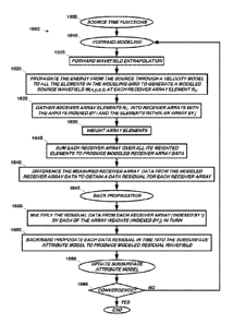
arrays such as the receiver array 801 in Figure 8. Referring now to Figure 16
and
Figure 17, the FWI process 1600 begins (at 1605) with the source time
functions S(t)
1605. In the forward-modeling phase (at 1610), during the forward wavefield
extrapolation (at 1615), energy from the source (at 1605) is propagated (at
1620)
through a subsurface attribute model 1705 to all the elements in the modeling
grid.
As discussed above and as those in the art having the benefit of this
disclosure will
appreciate, there are several kinds of subsurface attribute models and any
suitable
model known to the art may be used. This particular embodiment employs a
velocity
model.
[00120] Performing the forward wavefield extrapolation in this manner produces
a modeled source wavefield 1/1/(x.y,z,t) 1710 for all time and space and, in
particular,
a modeled source wavefield W(x,y,z.t) at each receiver array element Rri. The
receiver array elements R,J are gathered (at 1625) into receiver arrays with
the
arrays indexed by i and the elements within an array by j. In this context,
"gather"
means to select which receivers are in the array, weighting them by the array
weights, and summing. Using a set of array weights Au (at 1715), each array of
the
element is weighted (at 1630).
[00121] Each receiver array is then summed over all its weighted elements (at
1635) to produce modeled receiver array data Ri 1720:
R,(t) = A, R;,1(t)
26
CA 02966931 2017-05-04
WO 2016/089892
PCT/US2015/063219
The measured receiver array data Di 1725 from the field are then differenced
(at
1640) with the modeled receiver array data 1720 to produce a data residual
E11730
for each receiver array.
[00122] In the second phase 1645 of back propagation, the FWI process 1600
back-propagates this data residual 1730. It is known in the art how to back
propagate a data residual recorded at a point receiver. The principle of
reciprocity
establishes the correct, consistent way to do this for data from a receiver
array: the
residual data E(t) 1730 from each receiver array (indexed by 1) is multiplied
(at 1650)
by each of the array weights for that array A,,1(t) 1750 (arrays indexed by i,
array
elements indexed by j) in turn:
E,,1(0 = A1,1 Ei(t)
Each resulting data residual array element ELM-) then becomes a source that is
backwards-propagated in time (at 1655) into the subsurface attribute model
1705, to
produce a modeled residual wavefield 1735 for all time and space.
[00123] In the third phase of the algorithm, the modeled source wavefield 1710
and modeled residual wavefield 1735 are used to produce a velocity-model
update
(at 1660). If the data are not sufficiently well modeled, the updated velocity
model
becomes a new starting model for another iteration (at 1665). Iterations
repeat until
convergence (at 1740). This method promotes consistency between the recorded
data and the numerical model of the recorded data. Those in the art having the
benefit of this disclosure will readily be able to modify known FWI techniques
in this
manner. More generally, these considerations will apply to any inversion
technique
that relies on using the mismatch between predicted and recorded seismic data
to
update an estimated earth model, for example seismic tomography.
[00124]The technique also admits variation. In an alternative embodiment, the
same work flow in Figure 16-Figure 17 is used to constrain what parts of the
data the
FWI is allowed to fit. In this embodiment the array weights 1715 in the FWI
algorithm
1600 are chosen to attenuate arrivals in the data that are not sensitive to
the desired
geological features of interest. The undesired arrivals are attenuated by
their
differing dip from the desirable arrivals. In this embodiment the receiver
arrays exist
only as an embellishment of the FWI algorithm, and do not model a physical
receiver
array deployed in the field. Not having been attenuated by receiver arrays,
the
undesired arrivals may be present in the data from the field, but the FWI is
27
CA 02966931 2017-05-04
WO 2016/089892
PCT/US2015/063219
constrained from fitting them. Note in this case we give up attempting to
maintain
consistency between the modeled and recorded data.
[00125] The FWI process 1600 illustrated in Figure 16-Figure 17 is a computer-
implemented process. The same general considerations governing computing
technology set forth above relative to Figure 3 also apply to the selection
and design
of the computing apparatus by which the FWI technique may be implemented. One
particular embodiment of such a computing apparatus is shown in Figure 18. The
computing apparatus is the computing apparatus 700 of Figure 7 modified to
also
implement the FWI process technique 1600.
[00126] More particularly, the computing apparatus 700' in Figure 18 has been
modified relative to the computing apparatus 700 in Figure 7 to implement the
FWI
process 1600 described above. The various data, models, etc. used in the
process
are stored on the mass storage 720 and include the source time functions S(t)
1700,
subsurface attribute model 1705, modeled receiver array data 1720, measured
receiver array data 1725, data residual 1730, and the modeled residual
wavefield
1735. The FWI can be performed by an FWI application 1800 stored on the server
710 and invoked by the user 1810 on a workstation 1805.
[00127] Note, however, that the FWI technique admits wide variation in how the
computing apparatus may be implemented. There is no requirement that it be on
the
same computing apparatus as the survey design. Nor is there any reason
necessarily that it be located in the same computing facility. Those features
are for
ease of illustration only. The computing apparatus for the FWI may be
completely
separate from the computing apparatus for the survey design and geographical
proximity is not requisite.
[00128] FWI has many uses in the seismic field __________________ generating
Earth models, for
example. Earth models also have many uses. Ultimately, they are part of a
process
by which the subterranean formations that they model are analyzed for
indications of
deposits of hydrocarbons or other fluids. The Earth models produced by the
modified FWI technique discussed above can similarly be used to detect such
indications.
[own] As is implicit in the discussion of the embodiment of Figure 2, the
presently disclosed technique admits wide variation in the temporal
relationship
between and amongst various implementations such as that disclosed in Figure
4.
The method 400 of Figure 4 assumes a linear, somewhat contemporaneous
28
CA 02966931 2017-05-04
WO 2016/089892
PCT/US2015/063219
relationship between, for example, the acquisition of the preliminary seismic
data (at
410) and the design of the low-frequency, marine survey (at 220). However,
many
embodiments may exploit the latitude in temporal relationships.
[own] As an example, at sufficiently low frequencies, the standard ocean-
bottom-node spacing will be unaliased for the relatively slower-moving surface
waves that constitute the bulk of the naturally occurring noise at frequencies
below 2
Hz. For example, 2000 m/s at 1 Hz has a Nyquist spacing of 1000 m. This is
larger
than the standard node spacing of ¨450 meters used in conventional ocean-
bottom
marine surveys. This means that receiver arrays can be formed out of (possibly
overlapping) patches of existing nodes in the receiver grid to attenuate the
naturally
occurring background seismic noise. So, for example the conventional ocean-
bottom receiver grid 518 shown in Figure 6 may be grouped into hexagonal
receiver
arrays 605 (three shown, only one indicated). If this allows us to extend the
usable
frequency range of our existing data to sufficiently low frequencies, this
alternative
processing may allow us to repurpose a conventional acquisition into a "low-
frequency" one. In particular, by forming receiver arrays to attenuate noise,
we may
extend the usable lower-frequency limit of conventional broadband sources such
as
airguns.
[00131] Thus, as shown in Figure 11, in this embodiment 1100, the design of
the low-frequency, marine seismic survey (at 220) may occur after it is
conducted (at
440'). The design of the receiver array (at 230') and the seismic source
shooting
plan (at 240') then comprises selecting how to combine receivers into patches
to
attenuate ambient noise and/or suppress undesirable data from the active
source by
including dip filtering in the algorithm. For the latter, sources could also
similarly be
combined into patches in an exactly analogous way. The receiver and/or source
arrays are then constructed and the data weighted and summed accordingly (at
1103) to provide the data that goes into the processing (at 450).
[00132] Since the low-frequency, marine seismic survey is conducted (at 440')
without regard to the naturally occurring background seismic noise 110, the
temporal
relationship of the preliminary seismic data acquisition (at 410) is
immaterial. It may
be acquired prior to, in parallel with, or after the low-frequency, marine
seismic
survey is conducted (at 440'). However, since it is this data from which the
naturally
occurring background seismic noise 110 is ascertained (at 420), it should be
29
CA 02966931 2017-05-04
WO 2016/089892
PCT/US2015/063219
performed at some point prior to the design of the low-frequency seismic
survey (at
220').
[00133] In this particular embodiment, since the low-frequency, marine seismic
survey has already been conducted (at 440), the design of the low-frequency,
marine survey (at 220') is conducted somewhat differently than it is in the
embodiments disclosed above. This occurs primarily in that the receiver
acquisition
grid and the source sail lines of the already recorded survey constrain the
design of
the attenuating receiver arrays (at 230') and the seismic source shooting plan
(at
240), respectively. Essentially, the design of the survey (at 220') must make
do with
what has gone before.
[00134] This constraint may manifest itself in several ways. For example, one
might arrive at a desired array design and a desired shooting plan, overlay
them on
what is available from the actually conducted survey, and then accept the
congruence between what is desired and what is available as the actual
designs. Or
one may actually constrain the design process arriving at the desired array
design
and shooting plan with what is available from the already conducted survey.
[00135] One way this might commonly happen is a so-called "piggyback"
survey, a low-frequency acquisition that takes advantage of the mobilization
and
nodes of a conventional acquisition to save costs. A low-frequency source and
a
conventional source will typically radiate in largely disjoint frequency
bands, in which
case their signals may be easily separated by bandpass filtering. Or, their
signals
may be easily separable using standard simultaneous-source separation
techniques.
Such separation is likely to be particularly successful if the signatures of
the two
kinds of sources are distinct, for example if the low-frequency source creates
energy
via sweeping or humming while the conventional airgun source is impulsive.
[00136] In either case, the signals from the low-frequency source(s) and
conventional source(s) may be separated in data processing_ In this case a low-
frequency survey and a conventional survey may be performed simultaneously,
which saves time and mobilization expense. However, the low-frequency
acquisition
may then have to make do with a node layout primarily designed for the
conventional
survey (for example the node layout shown in Figure 6). The node spacing
dictated
by the conventional survey may then, for example, influence the choice of
frequencies to use for the low-frequency survey. So, for example, a humming
acquisition frequency may be chosen such that the receiver node spacing allows
receiver arrays that are optimal for ambient noise suppression at that
frequency to
be formed from patches of nodes. Other examples may become apparent to those
skilled in the art having the benefit of this disclosure,
[00137] One suitable acquisition for this "piggyback" embodiment is
illustrated
in Figure 13A. In some embodiments, a seismic survey will be conducted in the
ocean 1300 over a subsurface target of geological interest 1326 which lies
beneath
the seafloor 1325. A vessel 1310 floating on the ocean surface 1320 will tow a
conventional airgun array 1340 and a streamer 1330 of receivers, e.g.,
hydrophones
1332 (only one indicated). These components comprise the "conventional
broadband acquisition" portion of the survey system.
[00138] The vessel 1310 may tow one or more low-frequency discrete-
frequency "humming" or narrowband sweeping sources 1350, each of which will
contain a receiver or sensor (not shown) that will record the wavefield
emitted by that
source as is often done. To enhance the low-frequency recordings, ocean-bottom
receivers 1335 may simultaneously be deployed and used in conjunction with the
conventional streamer 1330, or ocean-bottom receivers 1335 may be used without
streamers 1330. These comprise the "narrowband, low-frequency" portion of one
embodiment of the instant survey system.
[00139] In one particular embodiment, the humming or narrowband source is
implemented using the source disclosed and claimed in U.S. Letters Patent
8,387,744. However,
the technique is not limited to
acquisition with this particular source. Alternative embodiments may utilize
other
sources, for example a tunable bubble resonator source, so long as they are
capable
of use in acquiring humming and narrowband swept data as described above.
[00140] The airguns 1340 may be towed at shallow depths in order to
enhance their ability to generate higher-frequency acoustic waves. The low-
frequency sources 1350 are shown towed at deeper depths; in some embodiments
each will be towed at a depth appropriate for its frequency range, such that
the
surface ghost reflection maximally enhances the downward-propagating signal.
Thus, the deeper the depth of tow, the lower the frequency of the humming or
narrowband swept source. See, for example, U.S. Application Serial No.
12/291,221
or U.S, Letters Patent 7,257,049, which discuss the relationship between depth
and
frequency of acquisition. For some types of sources, the available frequency
range
shifts upwards with increasing depth, for example because an increase in water
31
Date Recue/Date Received 2021-04-20
CA 02966931 2017-05-04
WO 2016/089892
PCT/US2015/063219
pressure raises the resonant frequency of the source. Thus, in other
embodiments
the lower-frequency sources will be towed at shallower depths, despite the
attenuation from the surface ghost reflection that this may cause.
[00141] Many variations of this acquisition system are possible and well
within
the ability of one of ordinary skill in the art to devise. The instant survey
system
could acquire 2D, 3D, or 4D data. Variations in the design of the spread or
the
number of vessels will also be readily appreciated by those skilled in the art
having
the benefit of this disclosure. The low-frequency narrowband survey could be
performed at the same time as the conventional, higher-frequency broadband
survey, or in a separate pass, or in multiple separate passes. The
conventional and
low-frequency sources may be towed from the same boat, or more typically
different
boats.
[00142] The low-frequency sources 1350 could operate continuously. The
low-frequency sources could each operate at a single frequency or cycle
between
two or more discrete frequencies ("humming" low-frequency sources), or sweep
over
a narrowband range of low frequencies designed to augment the frequency range
produced by the broadband sources ("narrowband sweeping" low-frequency
sources). The sources could operate to produce waves of constant amplitude, or
the
amplitude of the waves could vary (taper up and down).
[00143] The one or more low-frequency humming datasets, one or more
narrowband sweeping datasets, and conventional broadband datasets may be
acquired in any order. In particular, they may be acquired sequentially, or
interleaved
by shot lines, or interleaved within a shot line, or acquired simultaneously
and
separated using any of the standard techniques known in the art, or in any
combination of these.
[00144] In this particular embodiment, a joint survey is conducted although
some embodiments may separate the broadband and low-frequency, narrowband
surveys. The conventional survey may proceed in accordance with conventional
practice. If the airguns emit waves with a detectable intensity at, for
example, 2.8
Hz, the highest of the low-frequency sources, it might be desirable to
slightly modify
the timing of each shot so that the 2.8 Hz wave component of the airgun signal
is
timed to be in-phase with the waves produced by the 2.8 Hz low-frequency
source(s). Note that at most this would require delaying or advancing the shot
timing
by 1.4 seconds. Alternatively, the vessel speed could be adjusted so that the
32
CA 02966931 2017-05-04
WO 2016/089892
PCT/US2015/063219
airguns reach their shot locations just at the desired point in the humming
source's
cycling. Note the energy of the acoustic signal produced from airguns rapidly
falls off
at lower frequencies, so any unwanted interference will be much reduced for
any
lower low-frequency sources.
[00145] The narrowband low-frequency sources may operate independently
or simultaneously. The narrowband low-frequency sources may operate
continuously or discontinuously. Each narrowband low-frequency source records
the
signal it is radiating, as this information will be used when performing the
full-
waveform inversion. The receivers could be recorded continuously. The
locations of
all sources and receivers will, in some embodiments, also be recorded
continuously.
[00146] In some alternative embodiments the seismic source is heavy enough
to hang nearly vertically underneath the source vessel. One such embodiment is
shown, in part, in Figure 13B . This is referred to, for present purposes, as
a "heavy
tow". More particularly, the seismic source(s) 1350' is(are) towed at a deep
depth
and at a steep tow angle. This is because the seismic source 1350', unlike
conventional marine seismic sources, is not designed to be neutrally buoyant.
It
therefore sinks and the tow line and/or umbilical accordingly bears the weight
of the
seismic source 1350', again unlike conventional practice.
[00147] In the illustrated embodiment, the "deep depth" is ¨60m, but this may
vary in alternative embodiments from, for example, ¨30m to ¨60m. The tow angle
is,
for present purposes, the deviation of the tow line from the vertical normal
to the
mean ocean surface 1320. In the illustrated embodiment, the steep tow angle is
¨15 off the vertical, but this may also differ among embodiments.
[00148] The heavy tow, if sufficiently close to the vertical, will generate a
vortex induced vibration ("VIV"), a phenomenon known to the art. There are
known
VIV suppression techniques, but these can be overwhelmed if the VIV becomes
severe enough. Thus, the precise measure of the steep tow will vary amongst
embodiments depending upon, for example, the angle of the tow, the severity of
the
VIV, and the number and effectiveness of VIV suppression techniques (if any)
that
are employed. Those in the art having the benefit of this disclosure may
discern and
appreciate other factors, as well. Thus, a "steep tow" angle is one that is
close
enough to vertical that VIV starts to become a problem. As noted above, some
embodiments may omit the heavy tow.
33
[00149] Although described in terms of marine acquisition, some of the
innovative concepts described herein could also apply to land acquisition. In
one
embodiment of a system for land acquisition, the method may include the
following:
1) forming sub-arrays out of a conventional coarse acquisition grid such as in
Figure
6, noting that the sub-arrays become dense at sufficiently low frequencies,
and for
those low frequencies can thus be used as receiver arrays that attenuate noise
by
filtering over wave number; 2) optimizing the design of a receiver array over
a narrow
or monochromatic frequency range, allowing for usable levels of attenuation
out of a
relatively small grid; 3) augmenting sparse-3D acquisition by replacing
conventional
receiver lines with 'fat receiver lines"; and 4) incorporating dip-filtering
into FWI.
[00150]
[00151] U.S. Application entitled, "Seismic Acquisition at Low Frequencies
with Deeply Towed, Heavy Seismic Sources", having priority to U.S. Provisional
Application No. 62/086,581 and with the inventors Andrew J. Brenders et al.
(Attorney Docket 500445 US P1).
[00152] U.S. Application Serial No. 61/896,394, entitled "Two Stage Seismic
Velocity Model", and filed October 28, 2013, in the name of the inventors
Andrew
Brenders and Joseph Dellinger, for its teachings regarding humming acquisition
and
FWI with data collected through humming acquisition.
[00153] U.S. Application Serial No. 13/327,524, entitled, "Seismic Acquisition
Using Narrowband Seismic Sources", filed December 15, 2011, in the name of the
inventors Joseph A. Dellinger et a/., published June 21, 2012, as U.S. Patent
Publication 2012/0155217, and commonly assigned herewith for its teachings
regarding data acquisition, and in particular, frequency humming sweeps
located at
11110024140040], [0054]-[0059], [00651400881.
[00154] U.S. Letters Patent 7.725,266, entitled, "System and Method for 30
Frequency Domain Waveform Inversion Based on 3D Time-Domain Forward
Modeling", and issued May 25, 2010, to BP Corporation North America Inc., as
assignee of the inventors Laurent Sirgue et al., for its teaching regarding
the full-
waveform inversion technique at column 7, line 64 to column 13, line 50, with
reference to Figures 3-5 therein.
34
Date Recue/Date Received 2021-04-20
[00155] U.S. Letters Patent 8,387,744, entitled, "Marine Seismic Source", and
issued March 5, 2013. to BP Corporation North America Inc., as assignee of the
inventors Mark Harper et al., for its teaching regarding the design and
operation of a
humming and narrowband seismic source at column 5, line 62 to col. 12, lines
46.
[00156] Carbonate Seismology, Vol. 6 (Palaz, et al. eds. SEG Books 1997).
The chapter is authored by Carl Regone and entitled "Measurement and
Identification of 3-D Coherent Noise Generated from Irregular Surface
Carbonate".
[00157]
[00158]Where reference is made herein to a method comprising two or
more defined steps, the defined steps can be carried out in any order or
simultaneously (except where context excludes that possibility), and the
method
can also include one or more other steps which are carried out before any of
the
defined steps, between two of the defined steps, or after all of the defined
steps
(except where context excludes that possibility).
[00159] Other embodiments of the invention will be apparent to those skilled
in
the art from consideration of the specification and practice of the invention
disclosed
herein. It is intended that the specification and examples be considered as
exemplary only, with a true scope and spirit of the invention being indicated
by the
following claims.
Date Recue/Date Received 2021-04-20