Note: Descriptions are shown in the official language in which they were submitted.
CONNECTION SYSTEM FOR TUNNELED CATHETERS
BRIEF SUMMARY
[0001] Briefly summarized, embodiments of the present invention are
directed to a catheter
for use in providing access to a vessel or other internal portion of a body of
a patient. In one
embodiment, the catheter is a dialysis catheter that includes initially
separate proximal and
distal catheter assembly portions to enable the catheter to be tunneled before
connecting the
two catheter assembly portions together. In particular, the embodiments herein
describe a
system for connecting the catheter assembly together such that the resultant
assembly provides
a leak-proof catheter.
[0002] The embodiments described herein are applicable to catheters that
are inserted in a
retrograde, or reverse tunneling, procedure, which procedure requires assembly
of the catheter
after the tunneling procedure has been performed. Such reverse-tunneled
catheter assemblies
are typically employed as acute or chronic dialysis catheters, central venous
catheters
("CVCs"), etc., though it is appreciated that a variety of catheter assemblies
and tubular
medical devices disposed within the patient body can benefit from the
teachings herein.
[0003] In one embodiment, a catheter assembly is disclosed that comprises a
proximal
catheter assembly portion and a distal catheter assembly portion. The proximal
catheter
assembly portion includes a bifurcating hub that defines at least one fluid
passageway. The
distal catheter assembly portion includes a catheter tube that defines at
least one lumen, with
the catheter tube including a polymeric material. A cannula assembly is also
disclosed and
includes at least one cannula that is operably connected with the fluid
passageway of the
birfurcating hub. The cannula is further configured to operably connect with
the lumen of the
catheter tube so as to provide fluid communication between the proximal
catheter assembly
portion and the distal catheter assembly portion when the two portions are
connected.
[0004] A polymeric coating is included with the cannula and the catheter
tube. The
polymeric coating is configured to provide a seal between the cannula and the
catheter tube
when the proximal catheter assembly portion and the distal catheter assembly
portion are
connected. Catheters having one, two, or more lumens can benefit from the
disclosure
discussed herein.
- 1-
Date Recue/Date Received 2022-02-14
[0005] These and other features of embodiments of the present invention
will become more
fully apparent from the following description and appended claims, or may be
learned by the
practice of embodiments of the invention as set forth hereinafter.
BRIEF DESCRIPTION OF THE DRAWINGS
[0006] A more particular description of the present disclosure will be
rendered by reference
to specific embodiments thereof that are illustrated in the appended drawings.
It is appreciated
that these drawings depict only typical embodiments of the invention and are
therefore not to
be considered limiting of its scope. Example embodiments of the invention will
be described
and explained with additional specificity and detail through the use of the
accompanying
drawings in which:
[0007] FIGS. 1A-2 depict various views of a catheter assembly according to
one
embodiment;
[0008] FIGS. 3A-3C depict various views of a catheter assembly according to
one
embodiment;
[0009] FIGS. 4A-4E depict various views of a catheter assembly according to
one
embodiment;
[00010] FIG. 5 is a perspective exploded view of a catheter assembly according
to one
embodiment;
[00011] FIG. 6 is a perspective view of a compression sleeve according to one
embodiment;
and
[00012] FIGS. 7A and 7B depict various views of a catheter assembly according
to one
embodiment.
DETAILED DESCRIPTION OF SELECTED EMBODIMENTS
[00013] Reference will now be made to figures wherein like structures will be
provided with
like reference designations. It is understood that the drawings are
diagrammatic and schematic
representations of exemplary embodiments of the present invention, and are
neither limiting
nor necessarily drawn to scale.
-2-
Date Recue/Date Received 2022-02-14
[00014] For clarity it is to be understood that the word "proximal" refers to
a direction
relatively closer to a clinician using the device to be described herein,
while the word "distal"
refers to a direction relatively further from the clinician. For example, the
end of a catheter
placed within the body of a patient is considered a distal end of the
catheter, while the catheter
end remaining outside the body is a proximal end of the catheter. Also, the
words "including,"
"has," and "having" as used herein, including the claims, shall have the same
meaning as the
word "comprising." Further, the words "at least one" as used herein, including
the claims, shall
be understood to include "one or more" in number.
[00015] Embodiments of the present invention are generally directed to a
catheter assembly
for use in providing access to a vessel or other internal portion of a body of
a patient. In
particular, the embodiments herein describe a system for connecting the
catheter assembly
together such that the resultant assembly provides a leak-proof catheter. The
embodiments
described herein are applicable to catheters that are inserted in a
retrograde, or reverse
tunneling, procedure, which procedure requires assembly of the catheter after
the tunneling
procedure has been performed. Such reverse-tunneled catheter assemblies are
typically
employed as acute or chronic dialysis catheters, central venous catheters
("CVCs"), etc.,
though it is appreciated that a variety of catheter assemblies and tubular
medical devices
disposed within the patient body can benefit from the teachings herein.
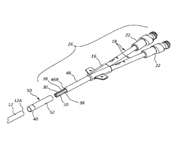
[00016] Reference is first made to FIGS. 1A-2, which depict details of a
catheter assembly
("catheter"), generally designated at 10, according to one embodiment. As
shown, the catheter
includes a catheter tube 12 defining two lumens 14 that extend between a
proximal end 12A
and a distal end 12B of the catheter tube. A septum 15 longitudinally extends
within the
catheter tube 12 to separate the lumens 14. Note that fewer or more lumens can
be defined by
the catheter tube. Note also that, though shown here as a dialysis catheter,
the catheter
assembly can include one of a variety of types of catheters or tubular medical
devices for
disposal in the body of the patient. In one embodiment, the catheter 10 is a
dialysis catheter of
14.5 French size, though other sizes of catheters are also possible.
[00017] A proximal end 12A of the catheter tube 12 is configured for operable
attachment
to a bifurcation hub 16 that provides fluid communication between each of the
lumens 14 of
the catheter tube and a corresponding one of extension legs 18, also operably
attached to the
bifurcation hub 16. As the catheter tube 12 of the present embodiment includes
two lumens
14, two extension legs 18 are included with the catheter 10 and the
bifurcation hub 16
-3-
Date Recue/Date Received 2022-02-14
correspondingly provides two internal fluid passageways 24 (FIG. 2) for
operable connection
of the lumens and corresponding extension legs. Each extension leg 18 includes
an extension
tube 19 through which fluid can flow to/from the bifurcation hub 16 and
corresponding catheter
tube lumen 14, a clamp 20, and a connector 22. The number of extension legs
can vary from
what is shown and described herein.
[00018] FIGS. 1A and 1B further show that the catheter 10 includes a proximal
catheter
assembly portion 26, which in the present embodiment includes the bifurcation
hub 16 and
extension legs 18, and a distal catheter assembly portion 28, which in the
present embodiment
includes the catheter tube 12. It is appreciated that the proximal and distal
catheter assembly
portions 26 and 28 can vary from what is shown in the present embodiment, as
will be
described.
[00019] In the present embodiment, two cannulae 30, also referred to herein as
a cannula
assembly, are permanently attached to and extend from a distal end of the
bifurcation hub 16,
best seen in FIG. 1B, and as such are included with the proximal catheter
assembly portion 26
in the illustrated embodiment. The cannulae 30 are each configured to be
received through the
catheter tube proximal end 12A of the distal catheter assembly portion 28 and
into a
corresponding one of the lumens 14, so as to operably connect the bifurcation
hub with the
lumens, thus establishing fluid communication therebetween and with the
corresponding
extension legs 18.
[00020] Each cannula 30 includes an outer surface 34 that defines a cannula
lumen 32. The
cannula lumen 32 extends between a proximal end 30A and a distal end 30B of
the respective
cannula 30. The outer surface 34 of each cannula 30 is shaped and sized so as
to fit into a
proximal portion of one of the correspondingly shaped lumens 14 of the
catheter tube 12 in an
interference-type fit. For instance, in the present embodiment, each of the
cannulae 30 defines
a generally semi-circular cross sectional lumen shape, matching the semi-
circular shape of the
catheter tube lumens 14. Each cannula 30 further includes an inner surface 36.
In another
embodiment, a non-interference, slip-type fit is used for the cannula-to-
catheter tube lumen
connection. In this case, a compression component can be employed to assist in
securing the
connection.
[00021] As mentioned, though here the outer surface 34 of each cannula 30
defines a
generally semi-circular cross-sectionally shaped lumen 32, other cross
sectional cannula lumen
-4-
Date Recue/Date Received 2022-02-14
shapes and numbers are possible to correspond with the lumen(s) of the
catheter tube, including
round, square, oval, etc. The cannulae 30 include a suitable material,
including stainless steel
or other metal, thermoplastics, etc. The cannulae 30 can be insert-molded into
the body of the
bifurcation hub 16 during manufacture thereof, or by other suitable processes.
[00022] FIG. 2 shows the manner of attachment between the cannulae 30 (of the
proximal
catheter assembly portion 26) and the lumens 14 of the catheter tube 12 (of
the distal catheter
assembly portion 28), where the cannulae are inserted past the proximal end
12A of the catheter
tube until the catheter tube proximal end seats against the distal end of the
bifurcation hub 16.
This connection is referred to herein as a cannulae/catheter tube interface
42. The cannulae
outer surfaces 34 and the lumens 14 of the catheter tube 12 are sized so as to
provide, in the
present embodiment, an interference fit therebetween in the present embodiment
so as to assist
in providing a leak-free interface. The relative length, size, and
configuration of the cannulae
30 can vary from what is shown and described herein. Further details regarding
cannulae-
equipped bifurcation hubs can be found in U.S. patent no. 7,875,019, entitled
"Connection
System for Multi-Lumen Catheter".
[00023] In one example implementation, the catheter 10 is a chronic dialysis
catheter and is
provided to the clinician prior to use with the proximal catheter assembly
portion 26 physically
separate from the distal catheter assembly portion 28. This enables the
clinician to insert the
distal segment of the distal catheter assembly portion 28 into the vasculature
of the patient,
then subcutaneously tunnel the proximal segment of the distal catheter
assembly portion such
that the proximal end 12A of the catheter tube 12 is exposed atop the skin
surface. The
proximal catheter assembly portion 28 can then be attached to the proximal end
12A of the
catheter 12 via the cannulae 30 to produce the cannulae/catheter tube
interface 42 and complete
the catheter assembly 10. The catheter assembly 10 can then be dressed and
prepared for use.
Tunneling of the distal catheter assembly portion 28 before attaching the
proximal catheter
assembly portion 26 enables the clinician to trim the catheter tube 12 of the
distal catheter
assembly portion to a desired length before completing catheter assembly.
[00024] In accordance with the present embodiment, the cannulae/catheter tube
interface 42
is configured so as to substantially prevent leakage therefrom after the above-
described
assembly of the catheter and use thereof. In particular, a polymeric coating
is applied at the
cannulae/catheter tube interface 42 to form a fluid-tight interface between
the cannulae 30 and
the catheter tube 12. This in turn prevents leakage from the cannulae/catheter
tube interface
-5-
Date Recue/Date Received 2022-02-14
42 even when the catheter 10 is under pressure, such as during fluid infusion
into the patient
body via the catheter.
[00025] In light of the above, in the present embodiment the outer surfaces 34
of both
cannulae 30 are coated with a polymeric coating ("coating") 38 to enable a
leak-free connection
to be established between the cannulae and the catheter tube 12 when joined
together, as has
been described above. In the present embodiment, the coating 38 for the outer
surface 34 of
the cannulae 30 includes a material that is substantially chemically similar
to that included in
the catheter tube 12 itself. For instance, in the present embodiment the
catheter tube 12 includes
polyurethane and the coating 38 is formed from polyurethane as well.
[00026] The use of a coating that is chemically similar to the material
included in the
catheter tube 12 enables the catheter tube to knit with the coating on the
outer surface 34 of the
cannulae 30 when the cannulae are inserted into the catheter tube lumens 14 as
described above
in connection with a dialysis catheter placement for instance. This serves as
a seal and helps
to provide a leak-free interface between the cannulae 30 and the catheter tube
12, even when
creep of the polymeric catheter tube material occurs over time. As used
herein, "seal" is
understood to include an engagement that prevents the passage of fluid
therethrough.
[00027] In one embodiment, a polyurethane or other urethane-based coating is
used with a
polyurethane or other urethane-based catheter tube. In another embodiment, a
silicone coating
is used with a silicone catheter tube. Other material combinations are also
possible, as
appreciated by one skilled in the art, including various polymer coatings for
use with catheter
tubes of various polymers. The coating 38 can be applied to the cannulae 30 or
other
component via one of various procedures, including dipping, spraying,
painting, deposition,
extruding, insert molding, etc.
[00028] In one embodiment, the outer surfaces 34 of the cannulae 30 can be
bead blasted
prior to application of the coating 28 to provide surface features on a high
surface-area finish
and improve coating adhesion. Other methods for providing a roughened or high
surface-area
finish to the cannula surface to be coated can also be employed, including
metal sputtering on
the cannula surface, acid etching, etc.
[00029] In one example, the composition of the polymeric coating 38 was
prepared by
dissolving polyurethane pieces into about 6 mL of a solvent, such as
tetrahydrofuran ("THF"),
in a beaker to form the coating as a polyurethane slurry. The polyurethane
pieces were cut
-6-
Date Recue/Date Received 2022-02-14
from a one-inch portion into slices of thickness from about .005 inch to about
0.010 inch. The
solvent and polyurethane were mixed until dissolving of the pieces was
complete. The outer
surfaces of two cannulae were bead blasted with 24 grit aluminum oxide media
at 60 p.s.i. for
about 15 to about 17 seconds to provide a medium coarse finish on the cannulae
surfaces. The
polyurethane slurry was then applied to the outer surfaces of two cannulae to
define the coating
thereon. The thickness of the coating on the outer surfaces of the cannulae
was from about
0.0045 inch to about 0.005 inch, though other coating thicknesses are, of
course, possible.
[00030] In another embodiment, the coating 38 is chemically dissimilar to the
material
included in the catheter tube 12, in contrast to the previous embodiment. Such
chemically
dissimilar coatings can also enhance the cannulae/catheter tube interface 42
and seal the
interface such that leaking is prevented. For instance, a silicone coating 38
can be applied to
the cannulae 30 or other location to seal with a polyurethane catheter tube
12, in one
embodiment. In another embodiment, a polyurethane coating 38 can be employed
to seal with
a silicone catheter tube 12. These and other examples are therefore
contemplated.
[00031] Note that, in one embodiment, the coating 38 can be applied to the
interior walls of
the catheter tube lumens 14 in addition to or instead of to the outer surfaces
34 of the cannulae
30. In another embodiment, the cannulae 30 can be configured to fit over the
outer perimeter
of the catheter tube 12 instead of being received within the lumens thereof In
this case, the
coating 38 can be applied to the inner surface 36 of the cannulae 30, the
outer surface of the
catheter tube 12 proximate the proximal end 12A thereof, or both surfaces, in
one embodiment.
As such, various different sealing configurations employing the coating 38 are
contemplated.
[00032] Note that the present disclosure contemplates that two chemically
similar materials,
in one embodiment, each include at least one common polymer, including
copolymers and
homopolymers, either alone or in combination with other materials so as to be
capable of
knitting together, or creating a chemical bond and a sealing function, when
the materials are
placed in intimate contact. Additionally, the present disclosure contemplates
that, in one
embodiment, chemically dissimilar materials do not share a common polymer such
that the
materials do not readily bond to one another in intimate contact but are still
able to provide a
sealing function.
[00033] In one embodiment, therefore, the material included in the coating 38
for coating a
surface of the cannula and/or catheter tube 12 (or other component to be
sealed) can include
-7-
Date Recue/Date Received 2022-02-14
one or more of the following (non-limiting): polyurethane ("PUR or PU"),
silicone ("SI"),
polyester ("PES"), polyethyleneterephthalate ("PET"), polyethylene ("PE"),
high density
polyethylene ("HDPE"), polyvinylchloride ("PVC"), low-density polyethylene
("LDPE"),
polypropylene ("PP"), polystyrene ("PS"), polyamides ("PA"), nylons,
acrylonitrilebutadiene
styrene ("ABS"), polycarbonate ("PC"), polycarbonate/acrylonitrile
butadienestyrene
("PC/ABS"), polyetheretherketone ("PEEK"), and polytetrafluoroethylene
("PTFE"). Also,
note that any of these materials can be used in any arrangement or combination
within
themselves or with another polymer, including copolymers and homopolymers.
Also, in one
embodiment the above materials can include additives and fillers for improved
mutual bonding
and mechanical properties. Note that the above-noted materials can also be
included in the
catheter tube 12 as well.
[00034] In light of the above, a method of manufacture of the catheter 10 in
one embodiment
includes providing a proximal catheter assembly portion, such as the proximal
catheter
assembly portion 26 discussed above in connection with FIGS. 1A-2 with two
cannulae 30 (or
other number of cannulae) permanently attached to the bifurcation hub 16 such
that each
cannula extends from the distal end of the bifurcation hub, as shown in FIG.
1B. A distal
catheter assembly portion is also provided, such as the distal catheter
assembly portion 28
discussed above in connection with FIGS. 1A-2, including a catheter tube 12
defining two
lumens (or other number of lumens) 14. The cannulae 30 are coated with the
polymeric coating
38 either before or after being permanently attached to the bifurcation hub 16
using one or
more of the processes described further above. As mentioned, the cannulae 30
may be bead
blasted or otherwise treated to provide a relatively roughened surface prior
to application of
the coating 38. As described the coating 38 assists in sealing the
cannulae/catheter tube
interface 42 when the cannulae 30 are operably connected to the catheter tube
12, as when each
cannula is received through the proximal end 12A of the catheter tube and into
the
corresponding lumen 14 thereof, to provide a leak-free connection. It is
appreciated that other
process steps can be included in the method as described while still residing
within the scope
of the present disclosure.
[00035] So
configured, the catheter 10 can be placed in a patient via a reverse-tunneling
procedure by first inserting the distal segment of the catheter tube 12, as
part of the distal
catheter assembly portion 26, into the vasculature of the patient so as to
position the distal end
12B of the catheter tube in a desired location within the vessel. The catheter
tube 12 can be
-8-
Date Recue/Date Received 2022-02-14
trimmed by the clinician as needed, for proper length. The proximal segment of
the catheter
tube 12 remains external to the vessel and is then tunneled through a
subcutaneous tunnel
defined by the clinician until the proximal end 12A of the catheter tube
extends from the tunnel.
[00036] After tunneling the proximal segment of the catheter tube 12, the
proximal catheter
assembly portion 28 is attached to the catheter tube via the polymer-coated
cannulae 30 being
received into the lumens 14 of the catheter tube through the proximal end 12A
thereof. This is
typically performed by the clinician manually grasping the bifurcation hub 16
and pushing the
cannulae 30 into the catheter tube lumens 14 until each cannula is fully
received into the
corresponding lumen. This action joins the proximal catheter assembly portion
26 with the
distal catheter assembly portion 28, forming a complete catheter assembly. As
has been
described, the intimate contact of the polymer coating of the cannulae 30 with
the polymer
material of the catheter tube 12 causes a knitting of the polymers, which
provides a sealing
effect for the cannulae/catheter tube interface 42, as desired. As will be
seen, a compression
component can be employed over the cannulae/catheter tube interface 42 to
assist with sealing
the interface. Note that, in another embodiment, the cannulae 30 need not be
completely
received into the lumens while still being able to provide a leak-free
cannulae/catheter tube
interface.
[00037] FIGS. 3A-3C depict various details of the catheter 10 according to
another
embodiment, wherein a proximal tube portion 46 is interposed between the
bifurcation hub 16
and the cannulae 30 to form part of the proximal catheter assembly portion 26.
The proximal
tube portion 46 is similar in construction to the catheter tube 12 of the
distal catheter assembly
portion 28, defining like number and like-shaped lumens, as best seen in FIG.
3B. FIG. 3B
further shows that a proximal end 46A of the proximal tube portion 46 is
received within and
permanently attached to the bifurcation hub 16, while the cannulae 30 extend
past a distal end
thereof. A securement cuff 40 is included about an exterior portion of the
proximal tube portion
46.
[00038] FIG. 3C shows the catheter 10 in an assembled state and ready for use,
with the
proximal and distal catheter assembly portions 26, 28 joined together via the
cannulae 30 at the
cannulae/catheter tube interface 42. In contrast, FIG. 3A shows the catheter
10 in a dissembled
state, with the proximal catheter assembly portion 26 separated from the
distal catheter
assembly portion 28, as it would be during a procedure to insert the catheter
10 into a vessel of
a patient, for instance. Note that the cannulae/catheter tube interface 42 of
FIGS. 3A-3C and
-9-
Date Recue/Date Received 2022-02-14
the securement cuff 40 are both are positioned within the subcutaneous tunnel
after joining of
the proximal catheter assembly portion 26 and the distal catheter assembly
portion 28 is
complete. As with previous embodiments, the coating 38 on the outer surface 34
of the
cannulae 30 provides a sealing effect and assists in ensuring a leak-free fit
between the cannulae
and the catheter tube 12.
[00039] As referred to above, FIGS. 4A-4E depict inclusion of a compression
component,
here a compression sleeve 50, with the catheter 10, according to one
embodiment. As shown,
the compression sleeve 50 includes an elongate, hollow body 52 defining a
lumen 54 that
extends between a proximal end 52A and a distal end 52B of the body. The
compression sleeve
body 52 defines a slit 56 that extends along the length thereof and through
the thickness of the
wall thereof. Either side of the slit 56 defines interengaging teeth 58 that
enable the lumen 54
to be selectively reduced in size so as to compress the cannulae/catheter tube
interface 42 when
the cannulae 30 are received into the catheter tube lumens 14, as described
above.
[00040] Before being compressed on to the catheter 10, the compression sleeve
50 can be
slidably disposed over either the catheter tube 12 or the proximal tube
portion 46. Once the
cannulae 30 have been fully received into the catheter tube lumens 14 via the
proximal end
12A of the catheter tube 12, the compression sleeve 50 can them be slid into
place over the
cannulae/catheter tube interface 42, which corresponds in the present
embodiment to the
junction point of the proximal end 12A of the catheter tube 12 and the distal
end 46B of the
proximal tube portion 46. Once the compression sleeve 50 is suitably
positioned, a hemostat
or other suitable device can be used to compress the sleeve body 52, by virtue
of advancement
of the sets of teeth 58 disposed on either side of the slit 56 past each
other. This compression
provides a tight fit between the outer surface 34 of the cannulae 30 and the
catheter tube 12 as
seen in FIG. 4C, thus assisting to prevent leaks at the cannulae/catheter tube
interface 42. Of
course, other suitable compression components can be employed.
[00041] In the present embodiment, the proximal end 52A of the compression
sleeve body
52 is positioned adjacent the securement cuff 40 after final placement of the
compression sleeve
is complete, as seen in FIGS. 4C-4E. The catheter 10 can then be retracted
into the tunnel so
that the compression sleeve 50 and the securement cuff 40 are disposed within
the tunnel, thus
protecting the cannulae/catheter tube interface 42 from potential
contamination from external
sources. Note that in one embodiment, the compression sleeve can be tapered in
shape so as
to ease passage into the tunnel. Note, that in another embodiment, heat may be
applied to the
-10-
Date Recue/Date Received 2022-02-14
cannulae/catheter tube interface 42 after joining of the proximal and distal
catheter assembly
portions 26, 28 in order to enhance the seal at the interface.
[00042] FIGS. 5-7B depict details of the catheter 10 according to another
embodiment,
wherein the securement cuff 40 is attached to the body 52 of the compression
sleeve 50 itself.
This, in turn, enables more flexibility in positioning the securement cuff 40
relatively more
distally or more proximally, depending on the orientation of the compression
sleeve 50. For
instance, FIG. 7A shows the compression sleeve 50 positioned such that the
securement cuff
40 attached thereto is in a distal position with respect to the remainder of
the compression
sleeve. In another configuration, the compression sleeve 50 can be flipped 180
degrees to
position the securement cuff 40 in a proximal position with respect to the
remainder of the
compression sleeve, similar to the orientation shown in FIG. 6.
[00043] Note that the securement cuff in one embodiment can be positioned in
any one of a
variety of positions along the length of the compression sleeve and that,
while permanently
secured in a particular position in the present embodiment, the securement
cuff in other
embodiments can be initially movable along the compression sleeve until
fixated in a desired
position, such as via use of an adhesive.
[00044] Embodiments of the invention may be embodied in other specific forms
without
departing from the spirit of the present disclosure. The described embodiments
are to be
considered in all respects only as illustrative, not restrictive. The scope of
the embodiments is,
therefore, indicated by the appended claims rather than by the foregoing
description.
-11-
Date Recue/Date Received 2022-02-14