Note: Descriptions are shown in the official language in which they were submitted.
CA 02967240 2017-05-10
1
2015410502 CA
Description
Title of Invention: RAILCAR
Technical Field
[0001]
The present invention relates to a railcar, and
especially, relates to a railcar that allows movement
toward a second end beam, of a first end beam when an
70 intended load is input.
Background Art
[0002]
A technique that protects a passenger room when high
external force acts on an end bodyshell by collision is
disclosed. For example, Patent Literature 1 discloses a
technique that disposes a first end beam and a second end
beam at an end portion in a longitudinal direction of an
underframe to dispose an energy absorber and a sliding
center sill between these first end beam and second end
beam.
[0003]
The sliding center sill includes a square-tubular-
shaped first beam member fastened to the first end beam,
and a square-tubular-shaped second beam member fastened to
CA 02967240 2017-05-10
2
201541 C 502 CA
the second end beam. An end portion of this first beam
member and an end portion of this second beam member are
opposed one another and fitted to one another. At this fit
portion, a plurality of mutually communicating holes are
drilled. A plurality of coupling members (rivets and
bolts) inserted into these plurality of holes combine the
first beam member with the second beam member.
[0004]
According to Patent Literature 1, when the first beam
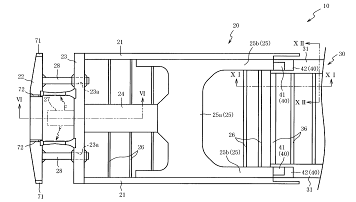
member collides with an oncoming car, the first beam member
and the second beam member are displaced mutually in
opposite directions to transmit a load to the coupling
members. When the load equal to or more than a
predetermined amount is transmitted to the coupling members,
the coupling members are broken to allow the first end beam
to move toward the second end beam. Thus, energy
transmitted from the first end beam to the second end beam
is absorbed by an energy absorbing member.
Citation List
Patent Literature
[0005]
Patent Literature 1: WO 2014/068885 (for example,
paragraphs 0012 and 0015, FIG. 3, and FIG. 4)
CA 02967240 2017-05-10
3
2015410502CA
Summary of Invention
Technical Problem
[0006]
However, in the above-described conventional
technique, the plurality of holes are drilled in the fit
portion of the first beam member and the second beam member,
each of the coupling members is inserted into each of these
plurality of holes, and the first beam member and the
second beam member are mutually displaced in the opposite
directions in consequence of the collision, thus having a
structure that breaks each of the plurality of coupling
members. Accordingly, due to a dimensional tolerance and a
positional tolerance of each of the holes and the coupling
members, the coupling members are broken to facilitate
generation of variation at the load that allows the first
end beam to move toward the second end beam. Therefore,
there has been a problem that, when the intended load is
input, it is difficult to allow the first end beam to move
toward the second end beam.
[0007]
The present invention has been made to solve the
above-described problem, and it is an object of the present
invention to provide a railcar that allows movement toward
a second end beam, of a first end beam, when an intended
load is input.
4
Solution to Problem
[0008]
A railcar according to a first aspect includes: an
underframe that includes a first end beam disposed at an end
portion in a car longitudinal direction and disposed to extend
along a car width direction and a second end beam disposed
separated from the first end beam to a car inner side and
disposed to extend along the car width direction;
an energy absorbing member that is arranged between the
first end beam and the second end beam and absorbs an energy
input from the first end beam and transmitted to the second
end beam in collision; and includes a fuse member that
couples the first end beam to the second end beam
along the car longitudinal direction and buckles to allow the
first end beam to move toward the second end beam when a load
received in the collision exceeds a predetermined value, and
the fuse member is formed of a channel material with an
approximately U-shaped cross-section, including a web disposed
to extend along the car longitudinal direction, and a pair
of flanges disposed upright from both edge portions of the
web.
[0009]
The railcar according to a second aspect, in the
railcar according to the first aspect, includes a first
gusset plate that bonds the flange at a side of the first
CA 2967240 2018-10-15
5
end beam of the fuse member to the first end beam, and a
second gusset plate that bonds the flange at a side of the
second end beam of the fuse member to the second end beam.
[0010]
The railcar according to a third aspect is the railcar
according to the second aspect, and at the fuse member, a low-
rigidity portion whose rigidity is lowered partially is formed
at a reference position between the first gusset plate and
the second gusset plate.
[0011]
The railcar according to a fourth aspect is the railcar
according to the third aspect, at the low-rigidity portion, a
height disposed upright from the web of the flange at the
reference position is lowered.
[0012]
The railcar according to a fifth aspect is the railcar
according to the fourth aspect, and the height disposed
upright from the web of the flange is continuously lowered
toward the reference position in a region between the first
gusset plate and the second gusset plate.
[0013]
The railcar according to a sixth aspect is the railcar
according to any one of the third to fifth aspects, and the
low-rigidity portion is formed such that a plate thickness
of the web at the reference position is thinned.
CA 2967240 2018-10-15
6
[0014]
The railcar according to a seventh aspect, in the railcar
according to the sixth aspect, includes a plurality of plate-
shaped plate members fixedly secured to a front surface or a
back surface of the web, and at the reference position, the
plate thickness of the web is thinned such that the plate
member is not secured.
[0015]
The railcar according to an eighth aspect, in the railcar
according to the seventh aspect, includes a connector arranged
at a bottom surface side of the second end beam, and projected
outside the first end beam of the car, and the plate member
positioned at the second end beam side among the plurality of
plate members has an edge portion fixedly secured to a surface
at a car outer side of the second end beam.
[0016]
The railcar according to a ninth aspect is the
railcar according to the third aspect, and the low-
rigidity portion is formed such that a height disposed
upright from the web of the flange at the reference
position is lowered and a plate thickness of the web at
the reference position is thinned, and at the web, the
plate thicknesses at three positions: the reference
position, a first position at the first end
beam side of the reference position, and a second position
CA 2967240 2018-10-15
7
at the second end beam side of the reference position, are
thinned.
[0017]
The railcar according to a tenth aspect is the railcar
according to the ninth aspect, and an edge portion of the first
gusset plate is positioned at the first position, and an edge
portion of the second gusset plate is positioned at the second
position.
Advantageous Effects of Invention
[0018]
The railcar according to the first aspect includes the
fuse member that couples the first end beam to the second end
beam along the car longitudinal direction, and the fuse member
buckles when the load received in the collision exceeds the
predetermined value to allow the first end beam to move toward
the second end beam, thus ensuring reduction of variation of the
load that allows the first end beam to move toward the second end
beam. Consequently, when an intended load is input, the first end
beam is allowed to move toward the second end beam.
[0019]
In particular, according to the first aspect, the fuse
member is formed of the channel material with the
approximately U-shaped cross-section, including the web
disposed to extend along the car longitudinal direction, and
the pair of flanges disposed upright from both edge portions
CA 2967240 2018-10-15
S
of the web. Thus, in normal operation (when the load is equal to
or less than the predetermined value), coupling strength between
the first end beam and the second end beam is ensured to ensure
improvement of the rigidity of a car end portion (an end portion
in the car longitudinal direction). In contrast, when receiving
the load that exceeds the predetermined value in consequence
of the collision, the fuse member promptly buckles to allow the
first end beam to move toward the second end beam.
[0020]
The railcar according to the second aspect, in addition
to the effect that the railcar according to the first aspect
provides, includes the first gusset plate that bonds the flange
at the first end beam side of the fuse member to the first end
beam, and the second gusset plate that bonds the flange at the
second end beam side of the fuse member to the second end beam.
Thus, when receiving the load in the collision, preceding
buckling of a base end side (a coupling part to the first end
beam or the second end beam) of the fuse member can be
restrained. That is, a central portion in the longitudinal
direction (the region between the first gusset plate and the
second gusset plate) of the fuse member can be buckled.
Accordingly, this facilitates to buckle the fuse member
into an intended shape. That is, when an intended load is
input, the fuse member is surely buckled to allow the first end
beam to move toward the second end beam.
CA 2967240 2018-10-15
9
[0021]
According to the railcar according to the third aspect,
in addition to the effect that the railcar according to the
second aspect provides, the low-rigidity portion whose
rigidity is lowered partially is formed at the reference
position between the first gusset plate and the second
gusset plate. Thus, with this low-rigidity portion as a base
point, the fuse member can be surely buckled. That is, this
facilitates to buckle the fuse member to the intended shape.
Consequently, when the intended load is input, the fuse
member is surely buckled to allow the first end beam to move
toward the second end beam.
[0022]
The low-rigidity portion may be formed by partially
changing a shape of the reference position, may be formed by
partially changing material of the reference position, and
these partial changes by the shapes and the materials may be
combined.
[0023]
According to the railcar according to the fourth aspect,
in addition to the effect that the railcar according to the
third aspect provides, the low-rigidity portion is formed such
that the height disposed upright from the web of the flange at
the reference position is lowered. Thus, with this low-
rigidity portion (a part at which the uprightly-disposed
CA 2967240 2018-10-15
10
height is lowered) as a base point, buckling in a mode where
the web is folded can be surely generated. That is, this
facilitates to buckle the fuse member into the intended
shape. Consequently, when the intended load is input, the
fuse member is surely buckled to allow the first end beam to
move toward the second end beam.
[0024]
According to the railcar according to the fifth aspect,
in addition to the effect that the railcar according to the
fourth aspect provides, the height disposed upright from the
web of the flange is continuously lowered toward the
reference position in the region between the first gusset
plate and the second gusset plate. Thus, with the low-
rigidity portion (the part the uprightly-disposed height is
lowered) as a base point, buckling in a mode where a back
side of the web is folded outside (an uprightly-disposed side
of the flange is an inside) can be surely generated.
[0025]
According to the railcar according to the sixth aspect,
in addition to the effect that the railcar according to any one
of the third to fifth aspects provides, the low-rigidity
portion is formed such that the plate thickness of the web
at the reference position is thinned. Thus, with this low-
rigidity portion (a part at which the plate thickness is
thinned) as a base point, the buckling in the mode where the
CA 2967240 2018-10-15
11
web is folded can be surely generated. That is, this
facilitates to buckle the fuse member into the intended shape.
Consequently, when the intended load is input, the fuse member
is surely buckled to allow the first end beam to move toward
the second end beam.
[0026]
The railcar according to the seventh aspect, in addition
to the effect that the railcar according to the sixth aspect
provides, includes the plurality of plate-shaped plate members
fixedly secured to the front surface or the back surface of the
web, and at the reference position, the plate thickness of
the web is thinned such that the plate member is not
secured. Thus, for example, compared with a case where the
plate thickness of the web is partially thinned by
performing a cutting work, man-hours can be reduced to
ensure reduction of a product cost to that extent.
[0027]
According to the railcar according to the eighth aspect,
in addition to the effect that the railcar according to the
seventh aspect provides, the plate member positioned at the
second end beam side among the plurality of plate members has
the edge portion fixedly secured to the surface at the car
outer side of the second end beam. Thus, enhancing the
coupling strength at the coupling part between the fuse
member and the second end beam can restrain this coupling
CA 2967240 2018-10-15
12
part from being folded. Accordingly, this facilitates to buckle
the fuse member into the intended shape.
[0028]
That is, when including the connector arranged at the
bottom surface side of the second end beam and projected outside
the first end beam, of the car, an oncoming car may collide with
the connector ahead, and in this case, the car is deformed in a
form that turns an end surface (the first end beam) downward
(lowers a head), by the load input from the connector. Thus,
large bending moment acts on the coupling part to the second end
beam, at the fuse member. Accordingly, as described above, the
edge portion of the plate member is fixedly secured to the
surface at the car outer side of the second end beam to enhance
the coupling strength at the coupling part between the fuse
member and the second end beam, thus ensuring resistance against
the bending moment to ensure restraining folding at the coupling
part.
[0029]
According to the railcar according to the ninth aspect,
in addition to the effect that the railcar according to the
third aspect provides, the low-rigidity portion is formed such
that the height disposed upright from the web of the flange at
the reference position is lowered and the plate thickness of the
web at the reference position is thinned, and at the web, the
plate thicknesses at the three positions; the reference position,
CA 2967240 2018-10-15
13
the first position at the first end beam side of the reference
position, and the second position at the second end beam side of
the reference position, are thinned. Thus, at the reference
position (the low-rigidity portion, that is, a part at which the
uprightly-disposed height is lowered and the plate thickness is
thinned), the fuse member is folded in a form that the back
side of the web is outside (the uprightly-disposed side of the
flange is the inside). At the first position and the second
position, the buckling in a mode that the back side of the
web is folded inside (the uprightly-disposed side of the
flange is the outside) can be surely generated. That is,
after the fuse member buckles, the load required for
deformation of this fuse member can be reduced.
[0030]
According to the railcar according to the tenth aspect,
in addition to the effect that the railcar according to the
ninth aspect provides, the edge portion of the first gusset
plate is positioned at the first position, and the edge
portion of the second gusset plate is positioned at the
second position. Thus, at the first position or (and) the
second position, when the web is folded, the flange
constrained by the first gusset plate or the second gusset
plate can be cut. Accordingly, after the fuse member buckles,
the load required for the deformation of this fuse member can
be reduced.
CA 2967240 2018-10-15
14
Brief Description of Drawings
[0031]
[FIG. 1] FIG. 1 is a side view of a railcar according to one
embodiment of the present invention.
[FIG. 2] FIG. 2 is a cross-sectional view of the railcar
along the line II-II in FIG. 1.
[FIG. 3] FIG. 3 is a cross-sectional view of the railcar
along the line in FIG. 1.
[FIG. 4] FIG. 4 is a front view of a carbody.
[FIG. 5] FIG. 5 is a partially enlarged top view of an
underframe.
[FIG. 6] FIG. 6 is a partially enlarged cross-sectional
view of the underframe along the line VI-VI in FIG. 5.
[FIG. 7] FIG. 7 is a partially enlarged top view of the
underframe.
[FIG. 8] FIG. 8 is a partially enlarged cross-sectional
view of the underframe along the line VIII-VIII in FIG. 7.
CA 2967240 2018-10-15
CA 02967240 2017-05-10
2015410502CA
[FIG. 9] FIG. 9 is a partially enlarged cross-sectional
view of the underframe along the line IX-IX in FIG. 7.
[FIG. 10] FIG. 10 is a
partially enlarged cross-
sectional view of the underframe along the line X-X in FIG.
5 8.
[FIG. 11] FIG. 11 is a partially enlarged cross-sectional
view of the underframe along the line XI-XI in FIG. 5.
[FIG. 12] FIG. 12 is a partially enlarged cross-sectional
view of the underframe along the line XII-XII in FIG. 5.
10 [FIG. 13] FIG. 13 is a partially enlarged cross-sectional
view of the carbody.
Description of Embodiments
[0032]
15 Hereinafter, a
description will be given of a
preferred embodiment of the present invention with
reference to the accompanying drawings. First, an overall
configuration of a railcar I will be described with
reference to FIG. 1 to FIG. 4.
[0033]
FIG. 1 is a side view of the railcar 1 according to
one embodiment of the present invention. FIG. 2 is a
cross-sectional view of the railcar 1 along the line II-II
in FIG. 1. FIG. 3 is a cross-sectional view of the railcar
1 along the line in FIG. 1.
CA 02967240 2017-05-10
16
2015410502CA
[0034]
As illustrated in FIG. 1 to FIG. 3, the railcar 1
mainly includes a carhody 2 internally including a
passenger room and an equipment room, bogies 3 that
supports this carbody 2 via air suspensions (not
illustrated), and wheels 4 journaled to these bogies 3.
The railcar 1 is a double-decker having upper and lower
two-layer passenger room structures to be formed as a
partially-low-floor car where parts of the bogies 3 in a
front and a rear are high-floored and a part between the
bogies 3 (a central portion in the car longitudinal
direction) is low-floored.
[0035]
The carhody 2 includes an underframe 10 that supports
a floor surface of a first floor, side bodyshells 60 whose
lower ends are coupled to side portions in a car width
direction (a right-left direction in FIG. 2 and FIG. 3) of
this underframe 10, end bodyshells 70 whose lower ends are
coupled to end portions in a car longitudinal direction (a
right-left direction in FIG. 1) of the underframe 10, a
roof bodyshell 80 coupled to upper ends of the side
bodyshells 60 and the end bodyshells 70, and a second-floor
floor member 90 positioned between the underframe 10 and
the roof bodyshell 80 to support a floor surface of a
second floor.
CA 02967240 2017-05-10
17
2015410502 CA
[0036]
Connectors 5 are arranged at the end portions in the
car longitudinal direction of the underframe 10. The
connector 5 projects outside the end bodyshell 70 in the
car longitudinal direction. A plurality of seats 6 are
disposed side by side at floor surfaces supported by the
underframe 10 and the second-floor floor member 90.
Baggage racks 7 are disposed to protrude from inner
surfaces of the side bodyshells 60 above these plurality of
seats 6. A plurality of window openings 61 are each
openingly formed at the first floor and the second floor,
and a plurality of door openings 62 are each openingly
formed at the low-floor parts at the first floor, at the
side bodyshells 60.
[0037]
FIG. 4 is a front view of the carbody 2 and
illustrates a state that an outer panel is removed to be a
frame. As illustrated in FIG. 4, the end bodyshell 70
includes a pair of corner posts 71 disposed to extend in a
vertical direction (an up and down direction in FIG. 4) at
both end portions in the car width direction, a pair of end
posts 72 that have predetermined distances in the car width
direction between these pair of corner posts 71 to be
disposed to extend in the vertical direction, and
reinforced beams 73 that couple the corner post 71 to the
CA 02967240 2017-05-10
18
2015410502 CA
end post 72 or the end posts 72 together in the car width
direction (a right-left direction in FIG. 4). Lower ends
of the corner posts 71 and the end posts 72 are coupled to
a first end beam 22 (the underframe 10, see FIG. 5), and
upper ends of the corner posts 71 and the end posts 72 are
coupled to the roof bodyshell 80, respectively.
[0038]
Next, a detailed configuration of the underframe 10
will be described with reference to FIG. 5 and FIG. 6. FIG.
5 is a partially enlarged top view of the underframe 10.
FIG. 6 is a partially enlarged cross-sectional view of the
underframe 10 along the line VI-VI in FIG. 5. FIG. 5 and
FIG. 6 schematically illustrate the connector 5 and an
energy absorbing member 27 using two-dot chain lines.
[0039]
As illustrated in FIG. 5 and FIG. 6, the underframe
10 includes a low-floor underframe 30 disposed at a center
portion in the car longitudinal direction (a right-left
direction in FIG. 5), high-floor underframes 20 arranged at
one side and another side in the car longitudinal direction
across this low-floor underframe 30 and upper and lower
positions are set higher than that of the low-floor
underframe 30, and a coupling member 40 that couples this
high-floor underframe 20 to this low-floor underframe 30 in
a posture that inclines downward from the high-floor
CA 02967240 2017-05-10
19
2015410502 CA
underframe 20 toward the low-floor underframe 30 (see FIG.
11), to be symmetrically formed in the car width direction.
[0040]
The high-floor underframe 20 includes a pair of side
beams 21 positioned at both sides in the car width
direction (an up and down direction in FIG. 5) to be
disposed to extend in the car longitudinal direction, a
first end beam 22 positioned at the end portion in the car
longitudinal direction to be disposed to extend in the car
width direction, a second end beam 23 disposed separated
from this first end beam 22 to an inner side (a right side
in FIG. 5) in the car longitudinal direction and disposed
to extend along the car width direction, a center sill 24
coupled to a center in the car width direction of this
second end beam 23, at one end to disposed to extend in the
car longitudinal direction, a body bolster 25 coupled to
another end of this center sill 24 and installed across the
pair of side beams 21 to be supported to the bogie 3 (see
FIG. 1), a plurality of floor-receiving beams 26 disposed
to extend in the car width direction, the energy absorbing
member 27 arranged between the first end beam 22 and the
second end beam 23, protruding members 28, and fuse members
F.
[0041]
The first end beam 22 is disposed separating outward
CA 02967240 2017-05-10
2015410502 CA
in the car longitudinal direction from end portions in the
longitudinal direction of the pair of side beams 21. As
described above, the lower ends of the pair of corner posts
71 are coupled to both ends in the longitudinal direction
5 of the first end beam 22, and the lower ends of the pair of
end posts 72 are coupled between these pair of corner posts
71. The second end beam 23 couples both end portions in
the longitudinal direction of the pair of side beams 21 in
the car width direction, and is positioned outward the
10 wheels 4 (see FIG. 1) in the car longitudinal direction.
[0042]
The lower end of the end post 72 is internally
inserted from an opening formed at a top surface of the
first end beam 22 to be coupled to inner surfaces (two
15 opposing surfaces in the car longitudinal direction and a
surface opposed to the opening) of the first end beam 22.
A plate-shaped reinforcing plate 29 is arranged inside the
second end beam 23 in a state where an outer edge of the
reinforcing plate 29 is coupled to inner surfaces (two
20 opposing surfaces in the car longitudinal direction and an
lower surface (a lower side in FIG. 6)) of the second end
beam 23.
[0043]
The center sill 24 is formed with curving downward
such that the end portion at a side of the second end beam
CA 02967240 2017-05-10
21
2015410502 CA
23 (a left side in FIG. 6) expands a dimension in an up and
down direction toward the outside in the car longitudinal
direction. An outward end surface in the car longitudinal
direction of this end portion is an installation surface
24a on which the connector 5 is installed. In this
embodiment, the installation surface 24a of the center sill
24 is formed approximately flush with a surface at an outer
side in the car longitudinal direction of the second end
beam 23.
[0044]
The body bolster 25 includes a body bolster center
portion 25a to which the other end at an inner side in the
car longitudinal direction of the center sill 24 is coupled
and disposed to extend in the car width direction, and body
bolster extended portions 25b coupled to the pair of side
beams 21 and disposed to extend in the car longitudinal
direction to be positioned at both sides in the car width
direction of the body bolster center portion 25a. The body
bolster 25 is formed to be approximately H-shaped from a
top view by these body bolster center portion 25a and body
bolster extended portions 25b.
[0045]
The energy absorbing member 27 is a member for
absorbing an energy transmitted from the first end beam 22
to the second end beam 23 such that, when the first end
CA 02967240 2017-05-10
22
2015410502 CA
beam 22 moves toward the second end beam 23 in consequence
of the collision, the energy absorbing member 27 is
compressed to be deformed between these first end beam 22
and second end beam 23. A base end of the energy absorbing
member 27 is coupled to the center in the car width
direction of the second end beam 23 in a state having a
predetermined distance from the first end beam 22. As the
energy absorbing member 27, a known configuration is
employable, thus omitting its detailed description.
[0046]
Here, the center sill 24 is coupled to a surface at
the inner side (the right side in FIG. 5) in the car
longitudinal direction at approximately a center in the car
width direction of the second end beam 23. The energy
absorbing member 27 is coupled to a surface at an opposite
side of this surface (the surface at the outer side in the
car longitudinal direction at the center in the car width
direction of the second end beam 23). Accordingly, the
first end beam 22 is moved toward the second end beam 23 in
collision. When the energy absorbing member 27 is
compressed, the center sill 24 supports the second end beam
23 from behind to ensure surely deforming (compressing) the
energy absorbing member 27, and the second end beam 23
deforms inward in the car longitudinal direction to ensure
reducing influence to the passenger room.
CA 02967240 2017-05-10
23
2015410502CA
[0047]
The energy absorbing member 27 has the predetermined
distance from the first end beam 22. Thus, by this
distance, at an early stage in the collision, this
facilitates to transmit the load input to the first end
beam 22 only to the fuse members F. Accordingly, this can
restrain the energy absorbing member 27 from being a
resistance against buckling of the fuse member F. That is,
when inputting the intended load, the fuse member F can be
surely buckled.
[0048]
The protruding member 28 is a member for guiding a
moving direction of the first end beam 22 to be disposed to
protrude from a surface at an inner side in the car
longitudinal direction of the first end beam 22 toward the
second end beam 23 along the car longitudinal direction.
The second end beam 23 includes a slide holding portion 23a
that is an opening penetrated along the car longitudinal
direction. This slide holding portion 23a receives a
protruding distal end of the protruding member 28 (a distal
end of the protruding member 28 is inserted into the slide
holding portion 23a). Thus, the protruding member 28 is
held to the slide holding portion 23a slidably along the
car longitudinal direction. That is, this can regulate the
moving direction toward the second end beam 23, of the
CA 02967240 2017-05-10
24
2015410502 CA
first end beam 22, to the car longitudinal direction, in
the collision.
[0049]
Here, the protruding member 28 is formed of a steel
pipe with a rectangular cross-section (steel material with
a closed cross-sectional structure). The slide holding
portion 23a is formed as the opening having an inner shape
identical to or slightly larger than an outer shape of the
protruding member 28. Forming the protruding member 28
with the steel pipe can endure bend and torsion, compared
with a case formed of an open cross-sectional or solid
member having an identical weight. Accordingly, this
ensures coupling strength between the first end beam 22 and
the second end beam 23 to ensure improvement of rigidity at
a car end portion (an end portion in the car longitudinal
direction).
[0050]
As described above, the slide holding portion 23a is
formed as the opening penetrated along the car longitudinal
direction at the second end beam 23. Thus, when the first
end beam 22 is moved toward the second end beam 23, the
slide holding portion 23a can receive the protruding member
28 using a space at a back side (the inner side in the car
longitudinal direction) of the second end beam 23. That is,
effect that guides the first end beam 22 along the car
CA 02967240 2017-05-10
2015410502 CA
longitudinal direction (slide displacement of the
protruding member 28 with respect to the slide holding
portion 23a) can be maintained until just before the first
end beam 22 abuts on the second end beam 23.
5 [0051]
Forming the slide holding portion 23a as the opening
of the second end beam 23 improves space efficiency to not
only ensure a passenger room space, but also ensure
rigidity of the slide holding portion 23a, compared with a
10 case where a different member arranged at a top surface or
a lower surface of the second end beam 23 slidably holds
the protruding member 28. Accordingly, the slide holding
portion 23a can strongly hold the protruding member 28, and
to that extent, the coupling strength between the first end
15 beam 22 and the second end beam 23 is ensured to ensure the
improvement of the rigidity of the car end portion (the end
portion in the car longitudinal direction).
[0052]
The fuse member F functions as a strength member that
20 ensures the rigidity of the car end portion (the coupling
part between the first end beam 22 and the second end beam
23) in normal operation. On the other hand, the fuse
member F is a member for allowing the first end beam 22 to
move toward the second end beam 23, by buckling when the
25 load received in the collision exceeds a predetermined
CA 02967240 2017-05-10
26
2015410502 CA
value. The fuse member F couples the first end beam 22 to
the second end beam 23 along the car longitudinal direction.
[0053]
When the first end beam 22 collides with an oncoming
car, the underframe 10 compresses the fuse members F in the
longitudinal direction between the first end beam 22 and
the second end beam 23. When the load exceeds the
predetermined value, the underframe 10 buckles this fuse
member F to allow the first end beam 22 to move toward the
second end beam 23.
[0054]
That is, in a structure of a conventional product
that breaks a plurality of coupling members such as rivets
and bolts to allow the first end beam 22 to move toward the
second end beam 23, influence of a dimensional tolerance
and a position tolerance of each of holes and the coupling
members gathers to facilitate to generate variation at
breaking strength. Thus, when the intended load is input,
it has been difficult to allow the first end beam 22 to
move toward the second end beam 23. However, as this
embodiment, the structure that uses the buckling of the
fuse member F ensures reducing variation of the load that
allows the first end beam 22 to move toward the second end
beam 23. Consequently, when the intended load is input,
the first end beam 22 is allowed to move toward the second
CA 02967240 2017-05-10
27
2015910502CA
end beam 23.
[0055]
A pair of sets (slide mechanisms) including the
protruding members 28 and the slide holding portions 23a
are arranged. These pair of slide mechanisms are
symmetrically disposed in the car width direction (in the
up and down direction in FIG. 5) across the energy
absorbing member 27. This can straightly guide (move along
the car longitudinal direction) the first end beam 22
toward the second end beam 23, for example, even when the
oncoming car collides being biased in the car width
direction to input an unbalanced load to the first end beam
22. Consequently, the fuse member F can be buckled by the
intended load, and the energy absorbing member 27 can be
stably compressed along the car longitudinal direction.
[0056]
Similarly, a pair of fuse members F are arranged.
These pair of fuse members F are symmetrically disposed in
the car width direction (the up and down direction in FIG.
5) across the energy absorbing member 27. This can uniform
the load required for the deformation in the buckling and
after the buckling of the fuse member F, in the car width
direction. That is, a posture with respect to the second
end beam 23, of the first end beam 22 inclines to ensure
restraining the protruding member 28 from getting
CA 02967240 2017-05-10
28
2015410502 CA
complicated inside the slide holding portion 23a.
Consequently, the slide displacement of the protruding
member 28 with respect to the slide holding portion 23a can
be smoothly performed.
[0057]
In this case, in this embodiment, the slide mechanism
(the set of the protruding member 28 and the slide holding
portion 23a) is disposed outside the fuse member F in the
car width direction (the upper side or the lower side in
FIG. 5). This facilitates to straightly guide (move along
the car longitudinal direction) the first end beam 22
toward the second end beam 23, for example, even when the
oncoming car collides being biased in the car width
direction to input the unbalanced load to the first end
beam 22. Consequently, this facilitates to buckle the fuse
member F by the intended load, and facilitates to stably
compress the energy absorbing member 27 along the car
longitudinal direction.
[0058]
Next, a detailed configuration of the fuse member F
will be described with reference to FIG. 7 to FIG. 10. FIG.
7 is a partially enlarged top view of the underframe 10.
FIG. 8 is a partially enlarged cross-sectional view of the
underframe 10 along the line VIII-VIII in FIG. 7. FIG. 9
is a partially enlarged cross-sectional view of the
CA 02967240 2017-05-10
29
2015410502CA
underframe 10 along the line IX-IX in FIG. 7. FIG. 10 is a
partially enlarged cross-sectional view of the underframe
along the line X-X in FIG. 8.
[0059]
5 As illustrated in FIG. 7 to FIG. 10, the fuse member
F includes a channel material 50 that couples the first end
beam 22 to the second end beam 23, three plate-shaped
bodies (a first plate member 51, a second plate member 52,
and a third plate member 53) fixedly secured to this
10 channel material 50 at regular intervals along the
longitudinal direction, a first gusset plate 54 installed
across the first end beam 22 and the channel material 50,
and a second gusset plate 55 installed across the second
end beam 23 and the channel material 50.
[0060]
The channel material 50, which is a member forming a
frame of the fuse member F, is formed into an approximately
U-shaped cross-section, including a web 50a disposed to
extend along the car longitudinal direction (a right-left
direction in FIG. 7) and a pair of flanges 50b disposed
upright from both end portions (edge portions) of this web
50a. End surfaces in the longitudinal direction of the web
50a and end surfaces in the longitudinal direction of the
flange 50b are coupled to each of the first end beam 22 and
the second end beam 23, in a posture that the web 50a is
CA 02967240 2017-05-10
2015410502 CA
parallel to the vertical direction (the flange 50b is
parallel to a horizontal direction).
[0061]
In this way, the fuse member F is formed of the
5 channel material 50 with the approximately U-shaped cross-
section. Thus, the fuse member F ensures the coupling
strength between the first end beam 22 and the second end
beam 23 to ensure the improvement of the rigidity of the
car end portion in normal operation. On the other hand,
10 when receiving the load that exceeds the predetermined
value in consequence of the collision, the fuse member F
promptly buckles to allow the first end beam 22 to move
toward the second end beam 23.
[0062]
15 In this embodiment, the fuse member F is arranged in
a posture that an opening side (a side at which the flange
50b is disposed upright) of the channel material 50 is
opposed to an outside in the car width direction (a side of
the protruding member 28) (see FIG. 5). As described later,
20 the fuse member F can buckle in a mode that a back side (a
lower side in FIG. 7) of the web 50a is folded outside (an
uprightly-disposed side (an upper side in FIG. 7) of the
flange 50b is an inside), with a reference position Ps as a
base point. That is, the channel material 50 can be folded
25 to be doglegged to a direction separated from the
CA 02967240 2017-05-10
31
201541 C 502 CA
protruding member 28.
[0063]
Accordingly, as described above, turning the opening
side to the protruding member 28 can reduce interference of
the folded channel material 50 to the protruding member 28
to ensure disposing the fuse member F close to the
protruding member 28. This facilitates to obtain a guide
effect in a sliding direction by the slide mechanism (the
protruding member 28 and the slide holding portion 23a) to
ensure stably forming the buckling of the fuse member F.
[0064]
A thickness dimension of the channel material 50 (a
dimension between outer surfaces of the pair of flanges 50b,
and dimensions in up and down directions in FIG. 8 and FIG.
9) is configured approximately identical to thickness
dimensions of the first end beam 22 and the second end beam
23.
[0065]
The first gusset plate 54 and the second gusset plate
55 are each including upper and lower two plates. The top
surface and a lower surface of the first end beam 22 are
bonded on the outer surfaces of the respective flanges 50b
of the channel material 50 by the first gusset plate 54,
and the top surface and the lower surface of the second end
beam 23 are bonded on the outer surfaces of the respective
CA 02967240 2017-05-10
32
2015410502 CA
flanges 50b of the channel material 50 by the second gusset
plate 55, respectively.
[0066]
This can restrain a base end side (a coupling part to
the first end beam 22 or the second end beam 23) of the
channel material 50 from buckling on ahead, when the load
in consequence of the collision acts. That is, the
buckling in a mode that the channel material 50 is folded
at an approximately central part in the longitudinal
direction (a region between the first gusset plate 54 and
the second gusset plate 55) can be surely formed.
Consequently, the fuse member F (the channel material 50)
is facilitated to buckle into an intended shape.
[0067]
Here, at the fuse member F, a low-rigidity portion
whose rigidity is partially low is formed at the reference
position Ps between the first gusset plate 54 and the
second gusset plate 55. With this reference position Ps
(the low-rigidity portion) as the base point, the fuse
member F is configured to buckle in the intended shape.
The low-rigidity portion is formed by lowering an
uprightly-disposed height of the flange 50b and thinning a
plate thickness of the web 50a. This low-rigidity portion
will be described in the following.
[0068]
CA 02967240 2017-05-10
33
2015410502 CA
At the fuse member F, the low-rigidity portion is
formed at the reference position Ps such that the height
disposed upright from the web 50a (a dimension in an up and
down direction in FIG. 7) of the flange 50b is partially
lowered. This can generate the buckling in the mode that
the web 50a can be folded, with the reference position Ps
(the low-rigidity portion) as the base point, when the load
in consequence of the collision acts, to facilitate to
buckle the fuse member F into the intended shape.
[0069]
In particular, in this embodiment, at the channel
material 50, the height disposed upright from the web 50a
of the flange 50b is continuously lowered toward the
reference position Ps, in the region between the first
gusset plate 54 and the second gusset plate 55 (see FIG. 7).
That is, an outer edge of the flange 50b is formed to be
approximately V-shaped. This can cause the load acted in
consequence of the collision to stably focus on the
reference position Ps to ensure surely generating the
buckling in the mode that the back side (the lower side in
FIG. 7) of the web 50a is folded outside (the uprightly-
disposed side (the upper side in FIG. 7) of the flange 50b
is the inside) at the reference position Ps (the low-
rigidity portion).
[0070]
CA 02967240 2017-05-10
34
2015410502 CA
At the fuse member F, the low-rigidity portion is
also formed at the reference position Ps by thinning the
plate thickness of the web 50a. This can cause the load
acted in consequence of the collision to further focus on
the reference position Ps to ensure more surely generating
the buckling in the mode that the back side (the lower side
in FIG. V) of the web 50a is folded outside (the uprightly-
disposed side (the upper side in FIG. 7) of the flange 50b
is the inside) at the reference position Ps (the low-
rigidity portion).
[0071]
In this case, in this embodiment, fixedly securing
the plate-shaped bodies (the first plate member 51, the
second plate member 52, and the third plate member 53) to
the back surface (a surface at a side opposed to an
uprightly-disposed direction of the flange 50b) of the web
50a varies the plate thickness of the web 50a.
Specifically, fixedly securing the first plate member 51
and the second plate member 52 haying a predetermined
distance partially thins the plate thickness such that the
plate-shaped body is not secured at the reference position
Ps. This can reduce man-hours to ensure reduction of a
product cost to that extent, for example, compared with a
case of performing a cutting work to partially thin the
plate thickness of the web 50a.
CA 02967240 2017-05-10
2015410502CA
[0072]
The first plate member 51, the second plate member 52,
and the third plate member 53 are formed into horizontally
long rectangular shapes in front view. Accordingly,
5 fixedly securing these respective plate members 51 to 53 in
postures that these longitudinal directions are set along
the longitudinal direction of the channel material 50 (the
web 50a) can easily form thin parts (parts at which the
plate thickness is thinned) disposed to extend with an
10 equal width in a direction (the up and down direction in
FIG. 8) perpendicular to the longitudinal direction of the
web 50a.
[0073]
Here, it is also considered that an opening is
15 disposed at the web 50a to form the low-rigidity portion at
the reference position Ps. However, when the opening forms
the low-rigidity portion at the reference position Ps, it
cannot be regulated that the web 50a is folded to which
direction at the reference position Ps (the low-rigidity
20 portion) to make this folded direction instable. In
contrast, the structure that fixedly secures the plate-
shaped bodies to the back surface of the web 50a to form
the low-rigidity portion at the reference position Ps can
stably regulate the direction that the web 50a is folded.
25 That is, this ensures surely generating the buckling in the
CA 02967240 2017-05-10
36
2015410502 CA
mode that the back side (the lower side in FIG. 7) of the
web 50a is folded outside (the uprightly-disposed side (the
upper side in FIG. 7) of the flange 50b is the inside) at
the reference position Ps (the low-rigidity portion).
[0074]
The first plate member 51, the second plate member 52,
and the third plate member 53, as described above, are
disposed at regular intervals one another along the
longitudinal direction of the web 50a (a distance between
the first plate member 51 and the second plate member 52,
and a distance between the second plate member 52 and the
third plate member 53 are set to be identical).
[0075]
In contrast, a group including the respective plate
members 51 to 53 is disposed being biased to a side of the
second end beam 23 (a right side in FIG. 8), in the
longitudinal direction of the web 50a. Therefore, a
distance larger than the distances between the plate
members 51 to 53 is formed between the first end beam 22
and the first plate member 51. On the other hand, a
clearance is not formed between the third plate member 53
and the second end beam 23 (that is, an edge portion of the
third plate member 53 is fixedly secured (coupled) to the
second end beam 23).
[0076]
CA 02967240 2017-05-10
37
2015410502CA
This enhances coupling strength at a coupling part
between the fuse member F and the second end beam 23 to
ensure restraining this coupling part from being folded.
Accordingly, this facilitates to buckle the fuse member F
into the intended shape.
[0077]
That is, the connector 5 is arranged at a bottom
surface side of the second end beam 23, and this connector
5 is projected outside the first end beam 22 in the car
longitudinal direction (see FIG. 6). Therefore, the
oncoming car may collide with the connector 5 on ahead, and
in this case, the carbody 2 is deformed in a form that
turns the end bodyshell 70 (the first end beam 22) downward
(lowers a head) by the load input from the connector 5.
Thus, large bending moment acts on the coupling part to the
second end beam 23, at the fuse member F.
[0078]
Accordingly, the edge portion of the third plate
member 53 is fixedly secured to the surface at the outer
side (a left side in FIG. 8) in the car longitudinal
direction of the second end beam 23 to enhance the coupling
strength at the coupling part between the fuse member F and
the second end beam 23, thus ensuring resistance against
the above-described bending moment to ensure restraining
the fuse member F from being folded at the coupling part to
CA 02967240 2017-05-10
38
2015410502CA
the second end beam 23.
[0079]
The group including the respective plate members 51
to 53 is disposed being biased to the second end beam 23
side (the right side in FIG. 8) in the longitudinal
direction of the web 50a to ensure forming change of the
plate thickness of the web 50a at a first position P1 and a
second position P2, which are described later, and
increasing a size of the second gusset plate 55. That is,
this increasing of the size of the second gusset plate 55
will be also effective for resisting against the above-
described bending moment to restrain the fuse member F from
being folded at the coupling part to the second end beam 23.
[0080]
At the web 50a of the channel material 50, fixedly
securing the first plate member 51, the second plate member
52, and the third plate member 53 to the back surface thins
the plate thicknesses at three positions: the reference
position Ps, the first position P1 at a first end beam 22
side of this reference position Ps, and the second position
P2 at the second end beam 23 side of the reference position
Ps.
[0081]
Accordingly, when the load in the collision acts,
while folding the fuse member F in the form that the back
CA 02967240 2017-05-10
39
2015410502 CA
side (the lower side in FIG. 7) of the web 50a is outside
(the uprightly-disposed side (the upper side in FIG. 7) of
the flange 50b is the inside), as described above, at the
reference position Ps, in contrast, the buckling in the
mode that the back side of the web 50a is folded inside
(the uprightly-disposed side of the flange 50b is the
outside) can be generated at the first position PI and the
second position P2. This ensures reduction of the load
required for the deformation of the fuse member F after
this fuse member F buckles.
[0082]
In particular, in this embodiment, an edge portion of
the first gusset plate 54 is positioned at the first
position Pl, and an edge portion of the second gusset plate
55 is positioned at the second position P2. Thus, at one
or both of the first position Pl and the second position P2,
when the web 50a is folded in the above-described form, the
flange 50b constrained by the first gusset plate 54 or the
second gusset plate 55 can be cut along the edge portion of
the first gusset plate 54 or the second gusset plate 55.
Accordingly, after the fuse member F buckles, the load
required for the deformation of this fuse member F can be
further reduced.
[0083]
As described above, the lower end of the end post 72
CA 02967240 2017-05-10
2015410502CA
is coupled to the inner surface of the first end beam 22,
and the plate-shaped reinforcing plate 29 is arranged
inside the second end beam 23, in a state where the outer
edge of the reinforcing plate 29 is coupled to the inner
5 surface of the second end beam 23.
[0084]
In this case, the end post 72 and the reinforcing
plate 29 are disposed in a straight line along the car
longitudinal direction (see FIG. 10). These end post 72
10 and reinforcing plate 29, and the fuse member F are
disposed at positions that positions in the car width
direction (an up and down direction in FIG. 10) at least
partially overlap. That is, as viewed in the car
longitudinal direction (viewed in a right-left direction in
15 FIG. 10), the end post 72 and the reinforcing plate 29, and
the fuse member F at least partially overlap. In this
embodiment, the end post 72 and the reinforcing plate 29,
and the web 50a of the channel material 50 are disposed in
a straight line along the car longitudinal direction.
20 [0085]
When the oncoming car collides with the end bodyshell
70 (see FIG. 4), that is, even when the oncoming car
collides with a focus on a position higher than the first
end beam 22, this facilitates to transmit the load in the
25 collision to the fuse member F (the web 50a of the channel
CA 02967240 2017-05-10
41
2015410502aN
material 50) via the end posts 72. Consequently, the fuse
member F is buckled to ensure absorption of the energy by
the energy absorbing member 27.
[0086]
Regardless of whether the oncoming car collides at
the position higher than the first end beam 22 or directly
collides with the first end beam 22, the reinforcing plate
29 can support the fuse member F (the web 50a of the
channel material 50) that has received the load from a
rearward to ensure surely buckling the fuse member F (the
channel material 50).
[0087]
The description will be given returning to FIG. 5 and
FIG. 6. The low-floor underframe 30 includes a pair of
side beams 31 positioned at both sides in the car width
direction (the up and down direction in FIG. 5) to be
disposed to extend in the car longitudinal direction, and a
plurality of floor-receiving beams 36 disposed to extend in
the car width direction. As described above, the railcar 1
is formed as the partially-low-floor car, and the
underframe 10 is formed as an underframe structure where
the low-floor underframe 30 is coupled to the high-floor
underframe 20 whose upper and lower positions are set
higher than that of this low-floor underframe 30 by the
coupling member 40. This underframe structure will be
CA 02967240 2017-05-10
42
2015410502CA
described with reference to FIG. 11 to FIG. 13.
[0088]
FIG. 11 is a partially enlarged cross-sectional view
of the underframe 10 along the line XI-XI in FIG. 5. FIG.
12 is a partially enlarged cross-sectional view of the
underframe 10 along the line XII-XII in FIG. 5. FIG. 13 is
a partially enlarged cross-sectional view of the carbody 2,
and corresponds to a cross-section along the line XI-XI in
FIG. 5. FIG. 13 illustrates only a main configuration by
simplifying the drawing for easily understanding.
[0089]
As illustrated in FIG. 11 to FIG. 13, the coupling
member 40 includes a main body member 41 formed of a steel
pipe with the rectangular cross-section (steel material
with the closed cross-sectional structure), and upper and
lower pair of flange members 42 formed by projecting out
from outer surfaces at both end portions in the
longitudinal direction of this main body member 41, to
couple a lower surface of the body bolster extended portion
25b at the body bolster 25 of the high-floor underframe 20
to a top surface of the side beam 31 of the low-floor
underframe 30.
[0090]
The upper and lower pair of flange members 42 are
formed as plate-shaped bodies with rectangular shapes in
CA 02967240 2017-05-10
43
2015410502CA
front view that are parallel one another. The upper side
flange member 42 is formed having a size (a width
dimensions, and a right-left directional dimension in FIG.
12) coupled to the lower surface of the body bolster 25
(the body bolster extended portion 25b) and a lower surface
of the side beam 21, at the high-floor underframe 20.
[0091]
As described above, the high-floor underframe 20
includes the center sill 24 coupled to the center in the
car width direction of the second end beam 23 at the one
end to disposed to extend in the car longitudinal direction,
and the body bolster 25 coupled to the other end of this
center sill 24 (see FIG. 5), and the side bodyshell 60 is
coupled to the side beam 31 of the low-floor underframe 30.
Accordingly, when a car end compression load is input to
the high-floor underframe 20, this car end compression load
can be directly transmitted from the center sill 24 and the
body bolster 25 of the high-floor underframe 20 to the side
beam 31 of the low-floor underframe 30 via the coupling
member 40. This can disperse the car end compression load
on the side bodyshell 60 to ensure car strength against the
car end compression load.
[0092]
A first side post 63 coupled to the side beam 31 of
the low-floor underframe 30 at a lower end and disposed to
CA 02967240 2017-05-10
44
2015410502 CA
extend in the up and down direction (an up and down
direction in FIG. 13), and a first frame member 65 that
couples this first side post 63 to the side beam 21 of the
high-floor underframe 20 and is disposed to extend in the
car longitudinal direction (a right-left direction in FIG.
13) are arranged at the side bodyshell 60.
[0093]
Accordingly, when the car end compression load is
input to the high-floor underframe 20, this car end
compression load can be transmitted from the side beam 21
of the high-floor underframe 20 to the first side post 63
via the first frame member 65. That is, a route that
transmits the car end compression load to the side
bodyshell 60 can be further ensured separately from the
route by the coupling member 40. This facilitates to
disperse the car end compression load on the side bodyshell
60 to ensure the car strength against the car end
compression load.
[0094]
In this case, the first side post 63 of the side
bodyshell 60 is coupled to the second-floor floor member 90,
at an upper end. Accordingly, when the car end compression
load is input to the high-floor underframe 20, this car end
compression load also can be transmitted to the second-
floor floor member 90 via the first side post 63. This can
CA 02967240 2017-05-10
2015410502CA
disperse the car end compression load on the second-floor
floor member 90, in addition to the side bodyshell 60, to
ensure the car strength against the car end compression
load.
5 [0095]
A second side post 64 coupled to the side beam 21 of
the high-floor underframe 20 at a lower end and disposed to
extend in the up and down direction (the up and down
direction in FIG. 13) is arranged at the side bodyshell 60.
10 This second side post 64 is coupled to the second-floor
floor member 90, in the middle of the longitudinal
direction. Accordingly, when the car end compression load
is input to the high-floor underframe 20, this car end
compression load can be transmitted from the side beam 21
15 of this high-floor underframe 20 to the side bodyshell 60
and the second-floor floor member 90 via the second side
post 64. This can disperse the car end compression load on
the side bodyshell 60 and the second-floor floor member 90
to ensure the car strength against the car end compression
20 .. load.
[0096]
In this case, the lower end of the second side post
64 of the side bodyshell 60 is coupled to the side beam 21
of the high-floor underframe 20 at a position approximately
25 corresponding to a position at which the coupling member 40
CA 02967240 2017-05-10
46
2015410502CA
(the main body member 41 and the flange member 42) is
coupled to the body bolster 25 of the high-floor underframe
20 in the car longitudinal direction (the right-left
direction in FIG. 13). Thus, the car end compression load
input to the high-floor underframe 20 to be transmitted
from the center sill 24 and the body bolster 25 of this
high-floor underframe 20 can be efficiently transmitted to
the second side post 64 via the body bolster 25 and the
side beam 21. This facilitates to disperse the car end
compression load on the side bodyshell 60 to ensure the car
strength against the car end compression load.
[0097]
Further, the second side post 64 is coupled to the
roof bodyshell 80 at an upper end. Accordingly, when the
car end compression load is input to the high-floor
underframe 20, this car end compression load also can be
transmitted from the side beam 21 of this high-floor
underframe 20 to the roof bodyshell 80 via the second side
post 64. This also can disperse the car end compression
load on the roof bodyshell 80, in addition to the side
bodyshell 60 and the second-floor floor member 90, to
ensure the car strength against the car end compression
load.
[0098]
Here, similar to the main body member 41 of the
CA 02967240 2017-05-10
47
2015410502CA
coupling member 40, the first side post 63, the second side
post 64, and the first frame member 65 are formed of steel
pipes with the rectangular cross-sections (steel material
with the closed cross-sectional structure). Accordingly,
when receiving the car end compression load, buckling of
these respective members (the main body member 41, the
first side post 63, the second side post 64, and the first
frame member 65) can be restrained. Consequently, the car
strength against the car end compression load is ensured.
[0099]
Between the first side post 63 and the second side
post 64, an intermediate post and a plurality of
reinforcing beams are arranged (any of them is not
illustrated). The intermediate post is disposed to extend
in the up and down direction (the up and down direction in
FIG. 13) to couple the second-floor floor member 90 to the
first frame member 65. The reinforcing beams are disposed
to extend in the car longitudinal direction (the right-left
direction in FIG. 13) to couple the first side post 63 to
the intermediate post and the intermediate post to the
second side post 64.
[0100]
On a surface at a car room side of the first side
post 63, the second side post 64, and the intermediate post
(a side opposed to the outer panel, and a near side in a
CA 02967240 2017-05-10
48
2015410502CA
paper of FIG. 13), a shear plate is stretched (fixedly
secured). The shear plate, which is a plate-shaped body
with an approximately rectangular shape in front view, in
this embodiment, is arranged in a form installed across the
first side post 63 and the intermediate post, and across
the intermediate post and the second side post 64. This
ensures the car strength against the car end compression
load.
[0101]
As described above, the present invention has been
described based on the above-mentioned embodiment. It will
be appreciated that the present invention will not be
limited to the embodiment described above, but various
modifications are possible without departing from the
technical scope of the present invention.
[0102]
While in the above-described embodiment, a case where
the outer shape of the protruding member 28 is formed into
the rectangular cross-section has been described, this
should not necessarily be construed in a limiting sense.
The outer shape may be formed into a circular-shaped cross-
section. While a case where the protruding member 28 is
hollow has been described, this should not necessarily be
construed in a limiting sense. The protruding member 28
may be solid.
CA 02967240 2017-05-10
49
2015410502CA
[0103]
While in the above-described embodiment, as a method
that varies the plate thickness of the web 50a (partially
forms portions whose plate thicknesses are thin), a case
where the plurality of plate-shaped bodies (the first plate
member 51, the second plate member 52, and the third plate
member 53) are fixedly secured to the web 50a has been
described, this should not necessarily be construed in a
limiting sense. For example, performing a cutting work to
the web 50a may partially thin the plate thickness of the
web 50a. The method that fixedly secures the plate-shaped
bodies and the method that performs the cutting work may be
combined.
Reference Signs List
[0104]
1 railcar
5 connector
10 underframe
22 first end beam
23 second end beam
27 energy absorbing member
fuse member
50 channel material
5Ca web
CA 02967240 2017-05-10
2015410502CA
50b flange
51 first plate member (plate member)
52 second plate member (plate member)
53 third plate member (plate member)
5 54 first gusset plate
second gusset plate
Ps reference position
P1 first position
P2 second position