Note: Descriptions are shown in the official language in which they were submitted.
CA 02967343 2017-05-10
WO 2016/077447 PCT/US2015/060132
AN ATTACHMENT FOR MAKING UP OR BREAKING OUT PIPE
Field
[0001] This disclosure relates to a pipe handling attachment that is
attachable to the end of an
arm of a prime mover, for example an excavator, crane, knuckle boom loader,
trackhoe, backhoe,
or other piece of heavy construction equipment for use in making up or
breaking out pipe during
assembly or disassembly of pipe.
Background
[0002] When making up (i.e. connecting) or breaking out (i.e. disconnecting)
drill pipe, casing,
tubing, or other pipe, tongs are used. Manual tongs, which are effectively
large wrenches, are
known for manually turning the pipe during make-up or break-out of pipe. Power
tongs or
power wrenches are also known that are pneumatically or hydraulically operated
tools that
operate to rotate the pipe during make-up or break-out.
[0003] Examples of attachments that are attachable to a prime mover for making
up and
breaking up pipe are described in U.S. Patent 8490519 and US Publication No.
2014/0151124..
Summary
[0004] A pipe handling attachment is described that is configured for
attachment to an arm of a
piece of heavy construction equipment, i.e. a prime mover, for example an
excavator, crane,
knuckle boom loader, a trackhoe, backhoe or the like. The attachment is
configured to rotate a
section of pipe during break-out (i.e. disconnection or disassembly) from
another section of pipe
and/or make-up (i.e. connection or assembly) with another section of pipe.
[0005] In one embodiment, the pipe handling attachment includes at least one
pipe roller
gripping assembly, and in another embodiment includes two or more pipe roller
gripping
assemblies. The pipe roller gripping assembly is configured to grip a pipe and
rotate the pipe
about a longitudinal axis of the pipe. The pipe roller gripping assembly is
movable in any
suitable manner, for example by pivoting, between a lowered position and a
raised position. This
permits the pipe roller gripping assembly to be moved out of the way during
certain pipe
1
CA 02967343 2017-05-10
WO 2016/077447 PCT/US2015/060132
handling operations. For example, when making up or breaking out a pipe
accessory such as a
reamer/hole opener, a crossover sub/thread adaptor, or a section of pipe
containing a valve, the
pipe roller gripping assembly can be moved out of the way to avoid
interference with the pipe
accessory while a vise assembly of the attachment is used to make-up or break-
out the pipe
accessory and an adjoining section of pipe. The lowered position of the pipe
roller gripping
assembly may also be referred to as a use position or as a retracted position.
The raised position
of the pipe roller gripping assembly may also be referred to as a non-use
position or as an
extended position.
[0006] As used throughout this description and claims, the word pipe, unless
otherwise
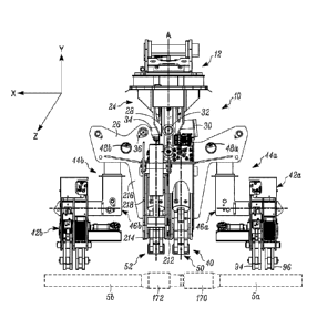
specified, is intended to encompass drill pipe, casing, tubing, or other pipe
designed to be
connected by threads with other sections of pipe. The pipe is hollow. The pipe
can be made of
any type of material including, but not limited to, metal or plastic. The word
pipe also
encompasses pipe accessories including, but not limited to, a reamer/hole
opener, a crossover
sub/thread adaptor, a valve, or any other accessory that is connected by
threads to a section of
pipe.
[0007] In addition, the pipes are described herein as having tool joints which
are defined as
enlarged and threaded ends of joints of drill pipe. However, the attachment
can be used with
pipe other than drill pipe, as long as the pipe is designed to connect to a
section of pipe via
rotation of the pipe.
[0008] As used herein, connecting/disconnecting one pipe section to/from
another pipe section
includes connecting/disconnecting a single pipe section or multiple pipe
sections. For example,
two or more pipe sections could be simultaneously connected to or disconnected
from the end of
a pipe string.
[0009] In one embodiment, the described attachment is configured to perform at
least three
primary functions. During a make-up operation where a first section of pipe is
to be connected
to a second section of pipe, the attachment can pick up the first section of
pipe, position the first
section of pipe relative to the second section of pipe for connection, rotate
the first section of
2
CA 02967343 2017-05-10
WO 2016/077447 PCT/US2015/060132
pipe relative to the second section of pipe to thread the pipe sections
together, and then torque
the joint between the pipe sections to complete the connection. During a break-
out operation
where a first section of pipe is to be disconnected from a second section of
pipe, similar
functions are performed but in reverse order. That is, during break-out, the
attachment is
configured to break the joint between the two pipe sections, rotate the first
pipe section relative
to the second pipe section to unscrew the first pipe section from the second
pipe section, and lift
the now disconnected first pipe section and place the first pipe section in
another location, for
example in a pipe stack on the ground or on a trailer.
[0010] Two of these functions involve rotation of the pipe by the attachment,
one rotation
occurring to initiate pipe break-out to begin disconnection of the pipe
sections or to torque the
joint to complete connection, and the other rotation occurring to unscrew the
first pipe section
from the second pipe section or to thread the first pipe section into the
second pipe section.
Therefore, it is to be understood that, unless otherwise noted, reference to
rotation of the pipe
section by the attachment encompasses either or both of the pipe break/joint
torquing rotation
and the pipe section unscrewing/screwing rotation.
[0011] It is also to be understood that, unless otherwise noted, reference to
rotation of the pipe
section by the attachment encompasses either or both of rotation during break-
out and during
make-up.
[0012] In one embodiment, a pipe handling attachment configured for attachment
to a prime
mover includes a head assembly that is configured to be attached to an arm of
the prime mover, a
main beam assembly pivotally mounted to the head assembly so that the main
beam assembly is
pivotable about a first pivot axis, at least one tilt actuator connected to
the head assembly and to
the main beam assembly to pivot the main beam assembly about the first pivot
axis, and a vise
assembly mounted on the main beam assembly. The vise assembly includes a
stationary vise and
a make/break vise that is rotatable relative to the stationary vise. In
addition, at least one, for
example two, pipe roller gripping assemblies are mounted on the main beam
assembly. The pipe
roller gripping assemblies are configured to grip a pipe and rotate a pipe
gripped by the at least
two pipe roller gripping assemblies about a longitudinal axis of the pipe.
Each of the pipe roller
3
CA 02967343 2017-05-10
WO 2016/077447 PCT/US2015/060132
gripping assemblies is movable relative to the vise assembly and the main beam
assembly
between a lowered position and a raised position, where at the lowered
position each of the pipe
roller gripping assemblies is disposed on one side of the first pivot axis and
at the raised position
each of the pipe roller gripping assemblies is disposed on an opposite side of
the first pivot axis.
[0013] In another embodiment, a pipe handling attachment configured for
attachment to a prime
mover includes an upper head assembly that is configured to be attached to an
arm of the prime
mover, a lower head assembly rotationally attached to the upper head assembly
to permit the
lower head assembly to rotate relative to the upper head assembly about a
rotation axis, a main
beam assembly pivotally mounted to the lower head assembly so that the main
beam assembly is
pivotable about a first pivot axis, at least one tilt actuator connected to
the lower head assembly
and to the main beam assembly to pivot the main beam assembly about the first
pivot axis, and a
vise assembly mounted on the main beam assembly. The vise assembly includes a
stationary
vise and a make/break vise that is rotatable relative to the stationary vise.
At least two gull-beam
assemblies are pivotally mounted to the main beam assembly for pivoting
movement upward and
downward relative to the main beam assembly between a lowered position and a
raised position
about second pivot axes each of which is parallel to the first pivot axis.
Pivot actuators are
connected to the main beam assembly and connected to the gull-beam assemblies
for pivoting
the gull-beam assemblies about the second pivot axes. In addition, each gull-
beam assembly
includes a pipe roller gripping assembly mounted on the gull-beam assembly.
[0014] In still another embodiment, a pipe handling attachment configured for
attachment to a
prime mover includes a head assembly that is configured to be attached to an
arm of the prime
mover, a support assembly pivotally mounted to the head assembly so that the
support assembly
is pivotable about a first pivot axis, at least one tilt actuator connected to
the head assembly and
to the support assembly to pivot the support assembly about the first pivot
axis, and a vise
assembly mounted on the support assembly. A pipe roller gripping assembly is
mounted on the
support assembly that is configured to grip a pipe and rotate a pipe gripped
by the pipe roller
gripping assembly about a longitudinal axis of the pipe, and that is movable
relative to the vise
assembly and the support assembly between a lowered position and a raised
position.
4
CA 02967343 2017-05-10
WO 2016/077447 PCT/US2015/060132
[0015] The pipe handling attachment(s) described herein can be configured
without the head
assembly and/or without one or more of the gull-beam assemblies. In other
words, the pipe
handling attachment can include just the vise assembly that is mounted on the
main beam
assembly/the support assembly which can be attached to any support structure
including, but not
limited to, an arm of a prime mover.
[0016] In addition, the pipe handling attachment(s) described herein can be
oriented
horizontally relative to the ground, vertically relative to the ground, or at
any angle between
horizontal and vertical.
Drawings
[0017] Figure 1 is a side view of one embodiment of a pipe handling attachment
with the gull-
beam assemblies at the lowered position.
[0018] Figure 2 is a side view of the pipe handling attachment of Figure 1
with the gull-beam
assemblies pivoted upward to the raised position.
[0019] Figure 3A is a bottom perspective view of the pipe handling attachment
with the gull-
beam assemblies pivoted upward to the raised position.
[0020] Figure 3B is an exploded view of the pipe handling attachment showing
the make/break
vise and the stationary vise dropped from their housings.
[0021] Figure 4 is a side view of the pipe handling attachment shown gripping
two sections of
pipe and with the vise assembly ready to initiate pipe break-out to begin
disconnection of the
pipe sections or to torque the joint to complete connection.
[0022] Figures 5A and 5B are end views of one of the pipe roller gripping
assemblies and of the
vise assembly, respectively, with the grab arms in an open position for
engaging the pipe.
CA 02967343 2017-05-10
WO 2016/077447 PCT/US2015/060132
[0023] Figures 6A and 6B are end views similar to Figures 5A and 5B but moved
into position
over the pipe and with the grab arms of the pipe roller gripping assembly
closed around the pipe.
[0024] Figures 7A and 7B are end views of the vise assembly showing different
rotational
positions of the make/break vise relative to the stationary vise during
make/break connection.
[0025] Figure 8 is a bottom perspective view of the pipe handling attachment
with the grab arms
of the pipe roller gripping assemblies closed around the pipe and the grab
arms of the vise
assembly open.
[0026] Figure 9 is a bottom perspective view of the pipe handling attachment
with the grab arms
of the pipe roller gripping assemblies closed around the pipe and the grab
arms of the vise
assembly closed for make/break connection.
[0027] Figure 10 is a close-up view of the portion contained in circle 10 of
Figure 8 illustrating
a lateral offset between the grab arms of the pipe roller gripping assembly.
[0028] Figure 11 is a close-up view of the portion contained in circle 11 of
Figure 9 showing the
grab arms of the vise assembly clamped around the pipe joint.
[0029] Figure 12 shows the pipe handling attachment tilted at an angle for
handling angled
sections of pipe.
[0030] Figure 13 shows the pipe handling attachment attached to an arm of a
prime mover and
handling attachment of a section of pipe to a reamer/hole opener.
[0031] Figure 14 is a side view of the pipe handling attachment of Figure 13
engaged with the
reamer/hole opener and the pipe section.
[0032] Figures 15A and 15B are perspective and sectional views, respectively,
of one
embodiment of a gull-beam assembly that can be used on the pipe handling
attachment.
6
CA 02967343 2017-05-10
WO 2016/077447 PCT/US2015/060132
[0033] Figures 16A and 16B are perspective and sectional views, respectively,
of another
embodiment of a gull-beam assembly that can be used on the pipe handling
attachment.
[0034] Figures 17A, 17B and 17C are perspective, end and top views,
respectively, of one
embodiment of a pipe roller gripping assembly that can be used on the pipe
handling attachment.
In Figure 17B, one of the plates of the arm housing is removed to show
interior construction of
the gripping assembly.
[0035] Figure 18 is an end view of another embodiment of a pipe roller
gripping assembly that
can be used on the pipe handling attachment.
[0036] Figure 19 is an end view of another embodiment of a pipe roller
gripping assembly that
can be used on the pipe handling attachment.
[0037] Figure 20 is an end view of another embodiment of a pipe roller
gripping assembly that
can be used on the pipe handling attachment.
[0038] Figure 21 is an end view of another embodiment of a pipe roller
gripping assembly that
can be used on the pipe handling attachment.
[0039] Figures 22A, 22B and 22C are perspective, a first sectional end view,
and a second
sectional end view, respectively, of another embodiment of a pipe roller
gripping assembly that
can be used on the pipe handling attachment.
[0040] Figures 23A and 23B are perspective and end views, respectively, of the
stationary vise
of the vise assembly.
[0041] Figures 24A and 24B are perspective and end views, respectively, of the
make/break vise
of the vise assembly.
7
CA 02967343 2017-05-10
WO 2016/077447 PCT/US2015/060132
[0042] Figures 25A and 25B are perspective and end sectional views,
respectively, of one
embodiment of a vise block assembly that can be used in either or both of the
make/break vise
and the stationary vise.
[0043] Figure 26 is an end sectional view of another embodiment of a vise
block assembly that
can be used in the either or both of the make/break vise and the stationary
vise.
[0044] Figure 26A is an end sectional view of another embodiment of a vise
block assembly
that can be used in the either or both of the make/break vise and the
stationary vise.
[0045] Figures 27A and 27B are perspective and end sectional views,
respectively, of another
embodiment of a vise block assembly that can be used in either or both of the
make/break vise
and the stationary vise.
[0046] Figures 28A, 28B and 28C illustrate an embodiment of an arm assembly
that can be used
in either or both of the make/break vise and the stationary vise.
[0047] Figures 29A and 29B illustrate another embodiment of an arm assembly
that can be used
in either or both of the make/break vise and the stationary vise.
[0048] Figures 30A, 30B and 30C illustrate another embodiment of an arm
assembly that can be
used in either or both of the make/break vise and the stationary vise.
[0049] Figures 31A and 31B illustrate another embodiment of an arm assembly
that can be used
in either or both of the make/break vise and the stationary vise.
[0050] Figures 32A, 32B and 32C illustrate another embodiment of an arm
assembly that can be
used in either or both of the make/break vise and the stationary vise.
[0051] Figures 33A and 33B illustrate another embodiment of an arm assembly
that can be used
in either or both of the make/break vise and the stationary vise.
8
CA 02967343 2017-05-10
WO 2016/077447 PCT/US2015/060132
[0052] Figures 34A and 34B illustrate another embodiment of an arm assembly
that can be used
in either or both of the make/break vise and the stationary vise.
[0053] Figure 35 illustrates another embodiment of an arm assembly that can be
used in either
or both of the make/break vise and the stationary vise.
[0054] Figures 36A and 36B illustrate another embodiment of an arm assembly
that can be used
in either or both of the make/break vise and the stationary vise.
[0055] Figures 37A and 37B illustrate another embodiment of an arm assembly
that can be used
in either or both of the make/break vise and the stationary vise.
[0056] Figure 38 illustrates an embodiment of a die that can be used on any
one of the vise
block assemblies or arm assemblies in Figures 25-37.
[0057] Figure 39 illustrates another embodiment of a die that can be used on
any one of the vise
block assemblies or arm assemblies in Figures 25-37.
[0058] Figure 40 illustrates another embodiment of a pipe handling attachment
described herein.
[0059] Figures 41A, 41B and 41C illustrate the pipe handling attachment
described herein
lifting the pipe up into the arms of the make/break vise and the stationary
vise.
[0060] Figures 42A, 42B and 42C are perspective views of the pipe handling
attachment
described herein holding a section of pipe and shifting the pipe toward or
away from another
section of pipe.
[0061] Figure 43 illustrates the pipe handling attachment described herein
being oriented
vertically for handling vertical pipe.
9
CA 02967343 2017-05-10
WO 2016/077447 PCT/US2015/060132
[0062] Figure 44 illustrates another embodiment of a pipe handling attachment
described herein.
[0063] Figure 45 illustrates still another embodiment of a pipe roller
gripping assembly that can
be used on the pipe handling attachment.
Detailed Description
[0064] With reference to all figures in this application, when reference is
made to the "a" side or
the "b" side of the attachment, reference numbers will be followed with an "a"
or "b"
respectively as shown in the figures throughout this application. Unless
otherwise noted herein
or apparent from the drawings, the "a" and "b" side of the attachment are
substantially identical
in construction, operation and function.
[0065] In addition, directional terms such as right, left, up or upward, down
or downward,
forward, backward, raised, lowered, and the like may be used. All such
directional terms are to
be interpreted based on Figure 1 where right and left are generally in the x-
direction; up, down,
raised, lowered or the like are generally in the y-direction or the x-y plane;
and forward and
backward or the like are generally in a z-direction into and out of the x-y
plane of Figure 1.
[0066] In some embodiments, the attachments described herein attach to a
single arm of the
construction equipment or prime mover, such as an excavator, track hoe, back
hoe, or similar
prime mover or heavy construction equipment.
[0067] In some embodiments, an attachment is defined herein as a tool that is
removably
mounted to the end of an arm of the construction equipment or prime mover, and
when mounted
modifies the construction equipment or prime mover to perform a completely new
scope of work
compared to a different type of attachment that can also be mounted to the end
of the arm. The
attachment can be removed from the arm of one piece of construction equipment
or prime
mover, and mounted to the arm of a different construction equipment or prime
mover.
[0068] With reference to Figures 1-3A, 3B, an attachment 10 is illustrated
that is configured to
rotate a section of pipe during break-out (i.e. disconnection or disassembly)
and/or make-up (i.e.
CA 02967343 2017-05-10
WO 2016/077447 PCT/US2015/060132
connection or assembly) with another section of pipe. Together, these two
operations can be
referred to as make/break operations. In one embodiment, the attachment 10 is
suitably
configured to mount to a piece of heavy construction equipment or prime mover
a portion of
which is visible in Figure 13. In the illustrated embodiment, the upper end of
the attachment 10
includes an upper head 12 that is configured to mount to an end of an
excavator boom arm 14.
However, the upper head 12 can be configured to permit connection of the
attachment 10 to
other construction equipment or prime movers.
[0069] As best seen in Figure 13, the upper head 12 includes a connection
point 16 that is
pivotally connected to the boom arm 14 by a pivot pin to allow the attachment
10 to pivot
relative to the boom arm 14 about an axis of the pivot pin, i.e. about the x-
axis direction, and a
connection point(s) 18 that is pivotally connected by a pivot pin(s) to boom
arm linkage 20 so
that the upper head 12 can pivot relative to the linkage 20. A hydraulic
actuating cylinder 22 of
the prime mover is connected to the linkage 20 for pivoting the attachment 10
about the pivot pin
of the connection point 16.
[0070] Returning to Figures 1-3A, 3B, the upper head 12 is suitably rotatably
connected to a
lower head 24 so that the lower head 24 can rotate about an axis A relative to
the upper head 12,
i.e. rotate about the y-axis direction. Together, the upper head 12 and the
lower head 24 form a
head assembly. Preferably, the lower head 24 is able to rotate continuously,
i.e. 360 degrees, in
either direction relative to the upper head 12. One example of rotatably
connecting an upper
head and a lower head is described in U.S. Patent 8,490,519 which is
incorporated herein by
reference in its entirety.
[0071] A main beam 26 is pivotally connected to the lower head 24 by a pivot
pin 28 to permit
the main beam 26 to pivot relative to the lower head 24 about the axis of the
pivot pin 28, i.e.
about the z-axis direction, which is perpendicular to the x-axis direction and
the y-axis direction.
At least one tilt actuator 30 is provided for causing tilting of the main beam
26. In the illustrated
embodiment, a single tilt actuator 30 is provided that is pivotally mounted
within the lower head
24 by a pivot pin 32 to permit the tilt actuator 30 to pivot about the axis of
the pin 32, with an
opposite end 34 of the actuator 30 fixed to the main beam 26 by a pivot pin
36. The tilt actuator
11
CA 02967343 2017-05-10
WO 2016/077447 PCT/US2015/060132
30 can be, for example, a hydraulic, pneumatic, electrical or mechanical
actuator that can extend
and retract for pivoting the main beam 26 relative to the lower head 24. The
axis of the pivot pin
32 is substantially parallel to the axis of the pivot pin 28 so that the main
beam 26 and the tilt
actuator 30 can pivot about parallel axes.
[0072] In another embodiment, two tilt actuators can be provided as described
in U.S. Patent
8490519.
[0073] Further information on pipe handling attachments that are attachable to
an excavator
arm, and having a pivoting main beam, lower head, tilt actuators and other
features, can be found
in US 2009/0057019 and US 2010/0308609, which are incorporated herein by
reference in their
entireties.
[0074] With continued reference to Figures 1-3A, 3B, a make/break vise
assembly 40 and pipe
roller gripping assemblies 42a, 42b are mounted on the main beam 26 via gull-
beam assemblies
46a, 46b and tilt with the main beam. As will be described further below, the
make/break vise
assembly 40 is configured to be disposed over the joint between two pipe
sections, and
configured to clamp one pipe section while clamping and rotating the second
pipe section in
order to either initiate breaking of the joint in the case of pipe break-out
or torqueing the joint
between the two pipe sections in the case of pipe make-up. As will also be
described further
below, the pipe roller gripping assemblies 42a, 42b are configured to grip a
section of pipe and
rotate the pipe section to unthread the pipe section from another pipe section
in the case of pipe
break-out or thread the pipe section onto another pipe section in the case of
pipe make-up. The
pipe roller gripping assemblies 42a, 42b are also configured to securely grip
a pipe section to
enable the attachment 10 under the power of the prime mover to move a pipe
section from one
point to another and to pick up a pipe section, such as from a pipe stack or
from the ground.
[0075] In the illustrated embodiment, the pipe roller gripping assemblies 42a,
42b are identical
in construction and, as discussed further below, are mounted on the gull-beam
assemblies 46a,
46b so that each assembly 42a, 42b can move axially in the x-axis direction
(independently from
each other or in synchronization with each other) relative to the main beam
26. In addition, as
12
CA 02967343 2017-05-10
WO 2016/077447 PCT/US2015/060132
discussed further below, each pipe roller gripping assembly 42a, 42b is also
mounted so as to be
moveable in the y-axis direction (independently from each other or in
synchronization with each
other). The pipe roller gripping assemblies 42a, 42b need not be identical in
construction, and
different pipe roller gripping assembly configurations can be used on the same
attachment 10.
[0076] In addition, each pipe roller gripping assembly 42a, 42b is mounted on
the respective
gull-beam assembly 46a, 46b and together they form an assembly 44a, 44b. The
gull-beam
assemblies 46a, 46b are pivotally attached to the main beam 26 on opposite
sides of the pivot 28
to permit the gull-beam assemblies 46a, 46b to pivot in the x-y plane between
the lowered
position shown in Figure 1 and the raised position shown in Figure 2. A pair
of actuators 48a,
48b (partially visible in Figures 1-3A, 3B) are disposed within the main beam
26 for actuating
the gull-beam assemblies 46a, 46b between the lowered position (shown in
Figure 1) and the
raised position (shown in Figures 2 and 3A, 3B).
[0077] The gull-beam assemblies 46a, 46b can be individually actuated by the
actuators 48a,
48b, or the gull-beam assemblies 46a, 46b can be actuated simultaneously.
Thus, a single one of
the gull-beam assemblies 46a, 46b can be pivoted to the raised position while
the other gull-
beam assembly remains in the lowered position, as shown in Figures 13 and 14.
Or both of the
gull-beam assemblies can be pivoted to the raised position as shown in Figures
2 and 3A, 3B.
The actuators 48a, 48b can be, for example, hydraulic, pneumatic, electrical
or mechanical
actuators that can extend and retract for pivoting the gull-beam assemblies
46a, 46b relative to
the main beam 26 to raise and lower the gull-beam assemblies, and the gripping
assemblies 42a,
42b mounted thereon, between the lowered and the raised positions.
[0078] Movement of the gull-beam assemblies 46a, 46b to the raised position
allows the pipe
roller gripping assemblies 42a, 42b to be moved upward out of the way in
certain circumstances
to avoid interference with pipe accessories. For example, when making up or
breaking out a pipe
accessory such as a reamer/hole opener 49 as shown in Figures 13 and 14, a
crossover sub, or a
section of pipe containing a valve, one or both of the pipe roller gripping
assemblies 42a, 42b
can be moved out of the way to avoid interference with the pipe accessory
while the make/break
13
CA 02967343 2017-05-10
WO 2016/077447 PCT/US2015/060132
vise assembly 40 of the attachment 10 is used to make-up or break-out the pipe
accessory and an
adjoining section of pipe.
[0079] The gull-beam assemblies 46a, 46b can be pivoted upward to the raised
position any
distance that is suitable for avoiding interference with pipe accessories such
as a reamer,
crossover sub, or valve. With reference to Figure 2, the gull-beam assemblies
46a, 46b can pivot
upward to at least the level L-L so that the pipe roller gripping assemblies
42a, 42b are disposed
above the level L-L. At this position, the pipe roller gripping assemblies
42a, 42b would be
considered to be completely or substantially disposed above the pivot 28,
completely or
substantially disposed above the make/break vise assembly 40, or approximately
or substantially
level with the main beam 26. In addition, at this position, the openings
defined by the grab arms
of the pipe roller gripping assemblies 42a, 42b in which the pipe is gripped
would face generally
in the x-axis direction.
[0080] As discussed further below, the make/break vise assembly 40 includes a
stationary vise
50 and a make/break vise 52. The vises 50, 52 are each designed to grip and
securely hold a
section of pipe on opposite sides of a joint between two sections of pipe,
with the make/break
vise 52 being configured to be rotatable relative to the stationary vise 50 to
rotate its gripped pipe
section to break the joint during break out/disconnection or to torque the
joint during make-up or
connection.
[0081] Specific details of the construction and operation of the make/break
vise assembly 40
and the gull-beam assemblies 46a, 46b will be provided below. However, the
general, overall
operation will be explained with reference to Figures 4-14.
[0082] First, an explanation of making up or connecting two sections of pipe
5a, 5b will be
explained. Breaking or disconnecting the two sections of pipe 5a, 5b is done
similarly, but
essentially in reverse order.
[0083] The two pipe sections 5a, 5b are initially brought close together end-
to-end as shown in
Figures 1 and 2. This can be done using the attachment 10 to carry and
position one pipe section
14
CA 02967343 2017-05-10
WO 2016/077447 PCT/US2015/060132
5a next to the other pipe section 5b as shown in Figures 42A and 42B. In one
embodiment, the
attachment 10 can then be used to initiate threading of the new pipe section
onto the end of the
other pipe section, and once initiated, the attachment 10 can be repositioned
to the position
shown in Figure 4 so that the stationary vise 50 is disposed over the end of
the pipe section 5a
and the pipe roller gripping assembly 42a is also disposed over the pipe
section 5a, while the
make/break vise 52 is disposed over the end of the pipe section 5b and the
pipe roller gripping
assembly 42b is disposed over the pipe section 5b. In another embodiment, once
the new pipe
section is brought close to the other pipe section, the attachment 10 can be
repositioned to the
position shown in Figure 4.
[0084] As shown in Figures 5A and 5B, the attachment 10 is lowered toward the
pipe sections
5a, 5b with grab arm assemblies 54a, 54b of the pipe roller gripping
assemblies 42a, 42b and vise
arm assemblies 56a, 56b of the vises 50, 52 initially opened to allow the grab
arm assemblies
54a, 54b and the vise arm assemblies 56a, 56b to fit over their respective
pipe sections 5a, 5b.
[0085] With reference to Figures 6A, 6B and 8, once the attachment 10 is
lowered into position
over the pipe sections 5a, 5b, the grab arm assemblies 54a, 54b of the pipe
roller gripping
assemblies 42a, 42b are then closed as shown in Figures 6A and 10 while the
vise arm
assemblies 56a, 56b of the vises 50, 52 remain open.
[0086] One of the pipe sections, such as the pipe section 5b, is then rotated
about its
longitudinal axis by the pipe roller gripping assembly 42b to thread or finish
threading the end of
the pipe section 5b into or onto the pipe section 5a.
[0087] In one embodiment discussed further below with respect to Figures 41A-
C, the pipe
roller gripping assemblies 42a, 42b can be actuatable vertically upward
relative to the gull-beam
assemblies 46a, 46b so as to be able to lift the pipe sections 5a, 5b upward
and into the arm
assemblies of the vises 50, 52.
[0088] Once the pipe sections 5a, 5b are threaded together, the vise arm
assemblies 56a, 56b are
then actuated closed to grip each pipe section 5a, 5b on opposite sides of the
joint as shown in
CA 02967343 2017-05-10
WO 2016/077447 PCT/US2015/060132
Figures 9 and 11 to torque the joint to finish the making up or connection
process. The
make/break vise 52 is then rotated relative to the stationary vise 50. Since
the vise arm assembly
56b of the make/break vise 52 is gripping the pipe 5b, rotation of the
make/break vise 52 rotates
the pipe 5b to complete the connection. Figure 7A shows that the make/break
vise 52 can be
rotated in a counterclockwise direction (when viewing Figure 7A) over an angle
a from its home
position. This counterclockwise rotation direction is suitable for achieving
torqueing of the joint
to finish the make-up process. The make/break vise 52 is also rotatable in a
clockwise direction
(when viewing Figure 7B) over an angle a from its home position. This
clockwise rotation
direction is suitable for initiating break-out or disconnection of the joint
during a break-out
process.
[0089] With reference to Figure 12, the two pipe sections 5a, 5b may be
disposed at an angle.
In such a situation, the attachment 10 can be pivoted about the pivot 28 by
the tilt actuator 30 so
that it is disposed at a corresponding angle 0 from horizontal.
[0090] In another embodiment illustrated in Figure 43, the pipe sections 5a,
5b can be oriented
vertically in which case the attachment 10 can also be oriented vertically. In
this embodiment,
the attachment 10 can be oriented vertically in any suitable manner including,
but not limited to,
rotation of the lower head 24 relative to the upper head 12 together with any
suitable
manipulation of the arm 14 of the prime mover, or by mounting the attachment
10 in a vertical
orientation on a suitable mounting structure other than the arm 14 of a prime
mover.
[0091] Figure 44 illustrates another embodiment of the attachment 10 where the
upper head 12
and the lower head 24 are removed. Instead, a generic mounting structure 600
is illustrated in
Figure 44 to indicate that the attachment 10 can be attached in any suitable
manner to any
suitable mounting structure, in a horizontal orientation, a vertical
orientation and any angle
between horizontal and vertical. Figure 44 also illustrates that the
attachment 10 can be used
without the gull-beam assemblies 46a, 46b and the pipe roller gripping
assemblies. Therefore,
the attachment 10 can be used with just the stationary vise 50 and the
make/break vise 52.
16
CA 02967343 2017-05-10
WO 2016/077447 PCT/US2015/060132
[0092] Figures 13 and 14 illustrate operation of the attachment 10 in the case
of the reamer 49
being connected to one of the pipe sections 5a, 5b. Due to the size of the
reamer 49 and its
proximity to the joint, if the attachment 10 is brought down toward the reamer
49 and the pipe
section, with the pipe roller gripping assemblies 42a, 42b in the lowered
position, the gripping
assembly 42b will contact the reamer 49 and prevent correct positioning of the
attachment 10.
Therefore, the gull-beam assembly 46b is pivoted upwardly out of the way to
the raised position
to permit correct positioning of the make/break vise assembly 40 over the
joint for connecting
the reamer 49 to the pipe section.
[0093] Gull-beam assemblies
[0094] The construction of the gull-beam assemblies 46a, 46b will now be
described with
reference to Figures 15A and 15B. The assemblies 46a, 46b are identical in
construction so only
the assembly 46a will be described in detail.
[0095] The gull-beam assembly 46a supports the pipe roller gripping assembly
42a. The gull-
beam assembly 46a includes an upper gull-beam 60 and a lower gull-beam 62. In
the illustrated
embodiment, the upper gull-beam 60 is telescoped within the lower gull-beam 62
in a manner
that permits the upper gull-beam 60 and the lower gull-beam 62 to move
relative to one another
in the vertical or y-axis direction. An upper end 63 of the upper gull-beam 60
is configured for
pivoting attachment to the main beam 26 to permit the entire gull-beam
assembly 46a to pivot as
discussed above. In addition, the upper gull-beam beam 60 defines an
attachment location 65 for
attaching to the actuator 48a.
[0096] As shown in Figure 15B, an actuator 64 is disposed within the upper
gull-beam 60 and is
attached at one end 66 to the upper gull-beam 60 and is attached at its
opposite end 68 to the
lower gull-beam 62. The actuator 64 can be, for example, a hydraulic,
pneumatic, electrical or
mechanical actuator that can extend and retract. When the actuator 64 extends,
the lower gull-
beam 62 is forced downward, thereby lowering the pipe roller gripping assembly
42a mounted
on the lower gull-beam 62 in the vertical or y-axis direction.
17
CA 02967343 2017-05-10
WO 2016/077447 PCT/US2015/060132
[0097] The lower gull-beam 62 also includes an actuator 70 disposed inside
thereof that can be,
for example, a hydraulic, pneumatic, electrical or mechanical actuator that
can extend and
retract. One end 72 of the actuator 70 is attached to the lower gull-beam 62
and the other end 76
of the actuator 70 is attached to a pin 78. The pin 78 includes an upper end
78a that extends
through and is slidable in a slot 80 formed in the lower gull-beam 62.
Similarly, a lower end 78b
of the pin 78 extends through and is slidable in a second slot 84 formed in
the lower gull-beam
62.
[0098] As discussed further below with respect to Figures 17-22, the pipe
roller gripping
assembly 42a includes a rectangular opening formed therein that allows the
pipe roller gripping
assembly 42a to be slidably disposed on the lower gull-beam 62. The pin 78 is
attached to the
pipe roller gripping assembly 42a such that when the actuator 70 extends and
retracts, the pipe
roller gripping assembly 42a is moved relative to the lower gull-beam 62
horizontally or in the x-
axis direction.
[0099] Therefore, the gull-beam assembly 46a achieves the vertical or y-axis
movements and
the horizontal or x-axis movements of the pipe roller gripping assembly 42a,
and the pivoting
movement of the pipe roller gripping assembly 42a between the raised and
lowered positions.
[0100] In another embodiment, the gripping assembly 42a can be fixed in
position on the lower
gull-beam 62, but the lower gull-beam can be movable in the x-axis direction
to shift the position
of the gripping assembly 42a.
[0101] Figures 16A and 16B illustrate another embodiment of the gull-beam
assembly 46a,b
that is constructed of a single beam structure 86. In this embodiment, the
gull-beam assembly
46a cannot move the pipe roller gripping assembly 42a vertically or in the y-
axis direction.
Instead, the gull-beam assembly 46a can move the pipe roller gripping assembly
42a horizontally
or in the x-axis direction, as well as pivot the pipe roller gripping assembly
42a between the
raised and lowered positions.
[0102] Pipe roller gripping assemblies
18
CA 02967343 2017-05-10
WO 2016/077447 PCT/US2015/060132
[0103] Embodiments of the pipe roller gripping assemblies 42a, 42b will now be
described with
reference to Figures 17-22. For sake of convenience, the gripping assemblies
will be assumed to
be identical in construction to one another, so only the assembly 42a will be
described in detail.
It is to be understood that the assembly 42b can be identical in construction
and operation to the
assembly 42a. Alternatively, the assemblies 42a, 42b can have different
constructions from one
another, for example the assembly 42a could have the construction described in
Figures 17A-C
and the assembly 42b could have the construction described in Figure 18.
[0104] Regardless of the specific construction, each pipe roller gripping
assembly has an arm
housing with an opening in the arm housing allowing the arm housing to be
disposed on the
respective gull-beam assembly, grab arm assemblies such as the grab arm
assemblies 54a, 54b,
means for actuating the grab arm assemblies between open and closed positions
for gripping the
pipe sections, and means for causing rotation of the pipe section while the
pipe section is gripped
by the grab arm assemblies.
[0105] With reference to Figures 17A-C, a first embodiment of the pipe roller
gripping
assembly 42a is illustrated. In this embodiment, the assembly 42a includes an
arm housing 90
formed by plates that are arranged parallel to each other. The plates include
aligned rectangular
openings that form a combined rectangular opening 92 through which the lower
gull beam 62 of
the gull-beam assembly 46a extends.
[0106] The grab arm assembly 54a includes a pair of grab arms 94, 96, with the
grab arm 94
pivotally mounted between two of the plates of the arm housing 90 by a pivot
pin 98, and the
grab arm 96 pivotally mounted between two other plates of the arm housing 90
by a pivot pin
100 so that, as seen in Figures 1 and 17A, the grab arms 94, 96 are
horizontally offset from one
another in the x-axis direction. Actuators 102 are attached to ends of the
grab arms 94, 96 for
pivoting the grab arms about the axes of the pivot pins to move the grab arms
94, 96 between an
open position (shown in Figure 17B) and a closed, gripping position shown in
Figure 17A. The
actuators 102 can be, for example, hydraulic, pneumatic, electrical or
mechanical actuators that
can extend and retract.
19
CA 02967343 2017-05-10
WO 2016/077447 PCT/US2015/060132
[0107] Each of the grab arms 94, 96 includes idler rollers 104 mounted
thereon. When a pipe
section 5a is held by the gripping assembly 42a in the grab arms 94, 94, the
idler rollers 104
allow the pipe section to rotate relative to the gripping assembly 42a about
the longitudinal axis
of the pipe section.
[0108] Rotation of the pipe section is caused by a pipe drive mechanism
disposed on the pipe
roller gripping assembly 42a. In particular, as shown in Figures 17A-C, two
pipe drive rollers
106, 108 are rotatably mounted between the plates of the arm housing 90 at a
location above the
pipe section. When the pipe section is grabbed by the grab arms 94, 96, the
pipe drive rollers
106, 108 are engaged with the upper surface of the pipe section. The pipe
drive rollers 106, 108
are driven by respective drive motors 110, 112 that are disposed on opposite
sides of the arm
housing 90. The drive motors 110, 112 are preferably reversible motors to
permit rotation of the
drive rollers 106, 108 in each direction.
[0109] Any form of drive connection between the drive rollers 106, 108 and the
drive motors
110, 112 can be used. In the embodiment illustrated in Figures 17A-C, the
drive motors 110,
112 directly drive the drive rollers 106, 108.
[0110] When the pipe drive rollers 106, 108 are rotated, the engagement
between the drive
rollers and the pipe section 5a causes the pipe section 5a to rotate about its
longitudinal axis.
Because of the idler rollers 104, the pipe section 5a rotates relative to the
grab arms. The drive
rollers 106, 108 can be formed from high friction rubber and/or can be
provided with other
friction enhancing features to increase the friction between the rollers and
the pipe surface.
[0111] Figure 18 illustrates an embodiment of a pipe roller gripping assembly
that is similar to
the embodiment in Figures 17A-C and like elements are referenced using like
reference numbers.
The embodiment in Figure 18 differs in that the two drive motors 110, 112 are
disposed on the
same side of the grab arm housing 90.
CA 02967343 2017-05-10
WO 2016/077447 PCT/US2015/060132
[0112] Figure 19 illustrates an embodiment of a pipe roller gripping assembly
that is similar to
the embodiments in Figures 17A-C and 18 and like elements are referenced using
like reference
numbers. The embodiment in Figure 19 differs in that the grab arms 94, 96
include at least one
drive roller 114 in place of or in addition to the idler rollers. Each drive
roller 106, 108 includes
a sprocket 116 connected thereto that drives a first endless drive 118 such as
a chain, belt, cable,
rope or the like which in turn drives an intermediate sprocket 120 disposed on
the grab arms 94,
96. A second endless drive 122 such as a chain, belt, cable, rope or the like
extends from the
intermediate sprocket 120 to a sprocket 124 connected to the drive roller 114.
With this drive
chain, rotation of the drive rollers 106, 108 by the drive motor(s) also
causes rotation of the drive
rollers 114. So the pipe section 5a is rotated by the drive rollers 106, 108
and by the drive rollers
114 on the grab arms 94, 96.
[0113] Figure 20 illustrates an embodiment of a pipe roller gripping assembly
that is similar to
the embodiments in Figures 17A-C, 18, and 19 and like elements are referenced
using like
reference numbers. In this embodiment, the drive motors 110, 112 are mounted
on the same side
of the grab arm housing as in Figure 18. The embodiment in Figure 20 differs
in that the grab
arm housing 130 is formed by a pair of plates and each of the grab arms 94, 96
are disposed
between the two plates so that the grab arms 94, 96 are aligned with or
positioned opposite one
another. The tips of the grab arms 94, 96 are modified to permit the tips to
overlap when the
grab arms are closed. For example, as shown in Figure 20, each grab arm 94, 96
can be formed
by a pair of grab arm plates 132, 134. The grab arm plate 132 of the grab arm
94 has an
extended tip 136 while the grab arm plate 132 of the grab arm 96 has a
truncated tip 138. The
grab arm plate 134 of the grab arm 94 has a truncated tip 138 while the grab
arm plate 134 of the
grab arm 96 has an extended tip 136. When the grab arms 94, 96 are closed, the
extended tips
136 overlap the opposing truncated tips 138, allowing the pipe section to be
substantially
encircled by the gripping assembly.
[0114] In addition, the drive rollers 106, 108 are disposed between the two
plates and are
horizontally aligned with one another along the x-axis direction.
21
CA 02967343 2017-05-10
WO 2016/077447 PCT/US2015/060132
[0115] Figure 21 illustrates an embodiment of a pipe roller gripping assembly
that is similar to
the embodiment in Figure 20 and like elements are referenced using like
reference numbers. In
this embodiment, a single drive motor 140 is used to drive the drive rollers
106, 108 via a drive
train that includes a central pinion gear 142 driven by the motor 140 that is
engaged with driven
gears 144, 146 which in turn are connected via respective shafts to the drive
rollers 106, 108.
[0116] Figures 22A-C illustrates an embodiment of a pipe roller gripping
assembly that is
similar to the embodiment in Figure 20 and like elements are referenced using
like reference
numbers. In this embodiment, instead of using drive rollers 106, 108 to rotate
the pipe, an
endless drive mechanism 150 is used to rotate the pipe 5a.
[0117] As shown in Figure 22A, the endless drive mechanism 150 is mounted to
one side of the
grab arm housing 130 and includes a first driven pulley 152 driven by a drive
motor 154, and a
pair of idler pulleys 154, 156. As best seen in Figure 22C, an endless drive
member 158 extends
around the pulleys 152, 154, 156 so that it can be rotated by the driven
pulley 152. The endless
drive member 158 can be any type of endless member that is suitable for
driving the pipe, for
example a belt, chain, cable, rope or the like. In one embodiment, the endless
drive member 158
can be a belt made of a high friction, no-slip material such as rubber or
other elastomeric
material. The drive member 158 is long enough such that between the pulleys
154, 156, the
drive member 158 can curve upward to form a curved drive section 160. In use,
the drive section
160 engages the upper surface of the pipe 5a as shown in Figure 22C such that
when the drive
member 158 is rotated, it causes the pipe 5a to rotate.
[0118] The pipe roller gripping assemblies illustrated in Figures 20, 21 and
22A-C can be used
with the attachment shown in Figure 1 in which case the grab arm housings 130
would include
the rectangular opening 92 for the beam as illustrated in dashed lines in
Figures 20, 21, 22A-C.
[0119] Figure 45 illustrates another embodiment of a pipe roller gripping
assembly can be used
with the attachment shown in Figure 1 or with any of the other attachments
described and/or
illustrated herein. Certain portions of the pipe roller gripping assembly,
such as the grab arm
housing (similar to the housing 130) having an opening (similar to the opening
92) to allow the
22
CA 02967343 2017-05-10
WO 2016/077447 PCT/US2015/060132
pipe roller gripping assembly to be slidably disposed on lower gull beam 62 of
the attachment,
are not illustrated to better illustrate the interior components of the pipe
roller gripping assembly.
[0120] In the embodiment illustrated in Figure 45, the pipe roller gripping
assembly includes the
pair of drive motors 110, 112 mounted on the same side of the grab arm housing
(similar to
Figures 18 and 20). However, in this embodiment, each drive motor 110, 112
drives a pair of the
drive rollers 106a, 106b, 108a, 108b. The drive rollers 106a, 106b are spaced
apart from one
another and rotate about the same axis. Similarly, the drive rollers 108a,
108b are spaced apart
from one another and rotate about the same axis. In this illustrated example,
the drive rollers
106a, 106b function together with the single grab arm 94 that includes one or
more of the idler
rollers 104 mounted thereon. The drive roller 108a, 108b function together
with a pair of the
grab arms 96 each of which includes one or more of the idler rollers 104
mounted thereof In
some situations, the use of the spaced drive roller pairs 106a, 106b, 108a,
108b achieves
increased driving engagement with the outside surface of the pipe to better
rotate the pipe. The
use of the drive rollers pairs 106a, 106b, 108a, 108b helps to reduce or
eliminate scissoring
action or forces on the pipe causing the pipe to skew that can sometimes occur
in the case of
using a single drive roller pair.
[0121] In one embodiment, the pipe roller gripping assemblies illustrated in
Figures 20, 21,
22A-C, and 45, or any of the other gripping assemblies described herein, can
be used with a pipe
handling attachment 500 illustrated in Figure 40. In the attachment 500,
elements that are
similar or identical to elements in the pipe handling attachment 10 are
referenced using the same
reference numbers.
[0122] The attachment 500 includes a main beam 502 that is similar in function
to the main
beam 26 and which can be pivotally mounted to a lower head (not shown) which
in turn can be
rotatably connected to an upper head (not shown) which can be similar to those
shown in Figure
1. A pair of gull-beam assemblies 504 are provided, each of which includes an
upper gull-beam
506 and a lower gull-beam 508. The upper gull-beams 506 are slidably disposed
in opposite
ends of the main beam 502. The upper gull-beams 506 are each slidable in the x-
axis direction
23
CA 02967343 2017-05-10
WO 2016/077447 PCT/US2015/060132
via an actuator 510 attached at one end to the main beam 502 and attached at
its other end to the
upper gull-beam 506.
[0123] Each lower gull-beam 508 is pivotally attached to the upper gull-beam
506 by pivot pin
512 that allows the lower gull-beam 508 to swing upward in the x-y plane to a
raised position
similar to the gull-beam assemblies 46a, 46b discussed above. The lower end of
the lower gull-
beam 508 is disposed between the two plates and two cross-plates that form a
housing 514 on the
arm housing. Therefore, the pipe roller gripping assembly is slidable on and
relative to the lower
gull-beam 508 in the y-axis direction.
[0124] An actuator 518 partially illustrated in dashed lines in Figure 40 is
disposed within each
of the lower gull-beams 508 and is attached at one end to the lower gull-beam
508 by a pin 519
and is attached at its other end to the pipe roller gripping assembly by a pin
520. The actuator
518 can extend and retract to slide the pipe roller gripping assembly
vertically up and down
relative to the lower gull-beam 508 or in the y-axis direction. Extension and
retraction of the
actuator 510 slides the upper gull-beam 506, together with the lower gull-beam
508 and the pipe
roller gripping assembly mounted thereon, horizontally or in the x-axis
direction.
[0125] A third actuator 522, partially visible in Figure 40, is disposed
within the main beam 502
and is fixed to the main beam 502 and to the lower gull beam 508 by a pin 524
to swing the
lower gull-beam 508 and the pipe roller gripping assembly mounted thereon
upward in the x-y
plane to a raised position as shown in Figure 40 similar to the gull-beam
assemblies 46a, 46b
discussed above as well as back down to the lowered position shown on the left
side of Figure
40.
[0126] The operation of the pipe roller gripping assemblieswill now be
described. The
operation will be discussed relative to one exemplary make-up operation where
a section of pipe
is unloaded from a pile of pipe, threading of the pipe onto a section of pipe
at the tail end of a
pipe string is initiated by the attachment before repositioning the attachment
to the position
shown in Figure 1, once repositioned the attachment completes threading, and
then the vise
assembly is used to torque the joint to the proper value. It is to be realized
that other sequences
24
CA 02967343 2017-05-10
WO 2016/077447 PCT/US2015/060132
in the make-up operation can be used, such as the attachment being positioned
as shown in
Figure 1 to initiate and complete threading of the pipe section onto the tail
end of the pipe string.
In addition, it is to be realized that the reverse order of operation can be
used during a pipe
break-out operation where after the joint is initially broken, the pipe roller
gripping assemblies
unthread the pipe section and then stack the pipe section in a pipe rack.
[0127] The attachment 10 is lowered toward the pile of pipe using the boom arm
14 (Figure 13)
in order to pick up the section of pipe to be threaded onto the pipe string.
The orientation of the
main beam 26 relative to the pipe can be adjusted, if necessary, via the
various adjustment
capabilities of the attachment 10 discussed above, including using the prime
mover actuator 22
to tilt the attachment 10, rotating the lower head 24 about the y-axis, using
the tilt actuator 30 to
tilt the main beam 26 about the axis z-axis as described above, and adjusting
the positions of the
pipe roller gripping assemblies.
[0128] Once the main beam 26 is correctly aligned with the pipe, the
attachment 10 is lowered
further toward the pipe. Once the pipe is positioned in the area between the
grab arms and the
pipe drive rollers 106, 108 with the pipe drive rollers firmly positioned
tangent to the pipe, the
grab arms are actuated to the closed position.
[0129] Once the pipe is secured in the pipe roller gripping assemblies, the
pipe is picked up.
Referring to Figure 1, the pipe 5a is then carried by the attachment 10 to a
position adjacent to a
tool joint 172 of a pipe 5b that is sticking out of the ground and to which a
tool joint 170 of the
pipe 5a will be connected. The prime mover operator then uses the various
adjustment
capabilities of the attachment to align the tool joint 170 of the pipe 5a to
the tool joint 172 of the
pipe 5b. It is expected that the operator would typically position the tool
joints of the pipes to,
for example, approximately one inch apart using the prime mover. The pipe
roller gripping
assemblies 42a, 42b can be shifted left or right in the x-axis direction
relative to the main beam
26 in order to permit axial shifting of the gripping assemblies 42a, 42b
during the threading (or
unthreading during break-out) operation.
CA 02967343 2017-05-10
WO 2016/077447 PCT/US2015/060132
[0130] For example, with reference to Figures 42A-C, an example of the
attachment 10 being
used to pick up a pipe section 5a, for example from the ground or from a pipe
stack, and
maneuvering the pipe section 5a to bring it close to the pipe section 5b for
threading is
illustrated. In Figure 42A, the pipe section 5a has been picked up by the
attachment 10. The
pipe section can then be brought toward the pipe section 5b to which the pipe
section 5a is to be
threaded onto.
[0131] Figure 42B shows the attachment 10 holding the pipe section 5a close to
the pipe section
5b, and the pipe roller gripping assemblies 42a, 42b being shifted to the left
on the lower gull-
beams 62 which shifts the pipe section 5a in the x-direction toward the end of
the pipe section
5b. The pipe roller gripping assemblies 42a, 42b are shifted on the lower gull-
beams 62 using
the actuators 70 and the pins 78 as described above.
[0132] Instead of shifting the pipe section 5a to the left, Figure 42C
illustrates the pipe roller
gripping assemblies 42a, 42b being shifted to the right on the lower gull-
beams 62 which shifts
the pipe section 5a in the x-direction away from the end of the pipe section
5b using the actuators
70 and the pins 78 as described above.
[0133] Once the tool joints 170, 172 are aligned, the gripping assemblies 42a,
42b are then
axially shifted in the appropriate direction until the threads on the tool
joints 170, 172 just
engage to permit threading. Once the tool joints 170, 172 are touching, the
pipe rotator motors
are started which rotate the pipe drive rollers 106, 108 thereby rotating the
pipe 5a about its
longitudinal axis. This threads the tool joint 170 of the pipe 5a onto the
tool joint 172 of the pipe
5b until the threads are fully seated. The pipe grab arms are then opened to
allow repositioning
of the attachment 10 to the position shown in Figure 1 over the joint. If the
pipe roller gripping
assemblies 42a, 42b are not needed to further rotate the pipe 5a, the gull-
beam assemblies 46a,
46b can be pivoted upward to the raised position shown in Figure 2. Or, in the
case of standard
pipe not involving a pipe accessory such as a reamer, the gull-beam assemblies
42a, 42b and the
gripping assemblies 42a, 42b mounted thereon can remain in position.
26
CA 02967343 2017-05-10
WO 2016/077447 PCT/US2015/060132
[0134] During threading and unthreading, the threads on the tool joints 170,
172 will tend to
cause one or both of the pipes 5a, 5b to move axially toward each other.
Typically, in a long
pipe string, the pipe 5b will not be able to move axially in which case the
pipe 5a must be
allowed some axial movement. Since the pipe 5a is securely gripped by the
assemblies 42a, 42b,
axial movement of the pipe 5a relative to the assemblies 42a, 42b is not
permitted. Instead, it is
believed that the boom arms 14 on many prime movers, such as excavators, have
enough play in
them to permit the boom arm 14 to move in a direction to allow the pipe 5a to
move axially
toward the pipe 5b. In the event that the boom arm 14 does not have any or a
sufficient amount
of play, another means of accommodating the axial movement will need to be
provided.
[0135] For example, as discussed above in Figures 15A-B and 16A-B, the
gripping assemblies
42a, 42b can be shifted axially using the cylinder 70. During threading or
unthreading when
axial shifting of the pipe 5a is required, the cylinders 70 of the gull-beam
assemblies 46a, 46b
can be put into a floating mode allowing free axial shifting of the assemblies
42a, 42b on the
gull-beam assemblies 46a, 46b. This will permit the axial shifting of the pipe
5a during
threading and unthreading. Once threading or unthreading is complete, the
cylinders 70 can be
locked to maintain the axial positions of the assemblies 42a, 42b.
[0136] The prime mover then lifts the attachment 10 off of the pipe 5a to
reposition the
attachment for use of the make/break vise assembly 40. The pipe 5a is now self-
supporting since
it is now threaded onto the pipe 5b. The make/break vise assembly 40 is then
used to torque the
joint between the pipes 5a, 5b and complete the threading of the pipe 5a onto
the pipe 5b.
[0137] The gripping of the pipe 5a by the assemblies 42a, 42b is sufficient to
securely hold the
pipe 5a at all angles, including holding the pipe 5a vertically for connection
to a vertical pipe that
is extending out of the ground.
[0138] Make/break vise assembly
[0139] The make/break vise assembly 40 will now be described with reference to
Figures 23A-
B, 24A-B and 25-39. The make/break vise assembly 40 is used to torque the tool
joint 170, 172
27
CA 02967343 2017-05-10
WO 2016/077447 PCT/US2015/060132
between the pipes 5a, 5b and finish connecting the pipes, or to initiate
breaking of the tool joints
between the two pipes.
[0140] As described above, the make/break vise assembly 40 includes the
stationary vise 50 and
the make/break vise 52. The stationary vise 50 is configured to clamp onto and
hold a tool joint
on one side of the joint using the vise arm assembly 56a, while the make/break
vise 52 is
configured to clamp onto the other tool joint of the second pipe on the other
side of the joint
using the vise arm assembly 56b and rotate the second pipe relative to the
first pipe.
[0141] Many different configurations of the stationary vise 50 and the
make/break vise 52 are
possible. Regardless of the specific construction, the stationary vise 50 and
the make/break vise
52 each include a vise arm assembly for securely clamping onto and holding a
respective tool
joint. In addition, the make/break vise 52 is configured to be rotatable
relative to the stationary
vise 50 torque the joint between the two pipes or break the joint between the
two pipes.
[0142] It is to be understood that the stationary vise 50 could instead be the
make/break vise,
and the make/break vise 52 could instead be the stationary vise. In addition,
it is to be
understood that the stationary vise 50 could also be configured as a
make/break vise 52 so that
the make/break vise assembly 40 includes two make/break vises, with the
make/break vises
being configured to permit one of them to be selectively fixed so as to
function as the stationary
vise.
[0143] The stationary vise 50 and the make/break vise 52 are each configured
to be
removable/replaceable as discussed further below with respect to Figure 3B.
[0144] With reference to Figures 23A-B, in one embodiment the stationary vise
50 is configured
generally similar to a box with a pair of spaced side plates 180, 182 and a
top plate 184. As best
seen in Figures 3A and 3B, the stationary vise 50 is attached to the main beam
26 by being
removably disposed within a housing structure formed by a side plate 185, a
side plate 212, and
front and rear plates 187a, 187b. The plates 185, 212, 187a, b are fixed to
the main beam 26 and
define a generally rectangular housing that receives the stationary vise 50
therein. Gusset plates
28
CA 02967343 2017-05-10
WO 2016/077447 PCT/US2015/060132
186 are connected between the main beam 26 and the side plate 185 to help
stiffen the side plate
185.
[0145] As shown in Figures 23A and 23B, aligned vertical slots 201 are formed
in the side
plates 180,182. A pin 218 extends through the slots 201 and through the
make/break vise 52 to
secure the stationary vise 50 in the housing structure. The slots 201 permit
vertical movements
of the stationary vise 50 within the housing structure formed by the plates
185, 212, 187a, 187b
so that the stationary vise 50 can freely float vertically up and down a
distance determined by the
pin 218 in the slots 201.
[0146] With reference to Figure 23B in which the plate 182 is removed for
clarity, the vise arm
assembly 56a of the stationary vise 50 is visible. The vise arm assembly 56a
includes a pair of
opposing, identical arm assemblies 190. Each arm assembly 190 includes a grab
arm 192 that is
pivotally mounted by a pivot pin 193 to the side plates 180, 182. One end of
the grab arm 192 is
attached to an actuator 194 which can be, for example, a hydraulic, pneumatic,
electrical or
mechanical actuator that can extend and retract to pivot the grab arm 192. The
other end of the
grab arm 192 has a gripping die 196 mounted thereto that is configured to
securely grip and hold
the outer surface of the pipe and prevent slipping between the pipe and the
gripping die 196.
Figure 23A shows the actuators 194 retracted so that the arm assemblies 190
are pivoted to an
open position so as to receive the respective tool joint. Figure 23B shows the
actuators 194
extended so that the arm assemblies are pivoted to a closed position securely
gripping the pipe.
[0147] Referring again to Figure 23B, to further help securely hold the pipe,
the stationary vise
50 further includes a vise block assembly 198 mounted therein at the top of
the pipe receiving
area. The vise block assembly 198 includes a pair of fixed gripping dies 200
that are arranged
relative to each other to form generally a V-shape to help clamp and hold the
pipe when the arm
assemblies 190 are closed.
[0148] With reference to Figures 24A-B, in one embodiment the make/break vise
52 includes a
pair of spaced side plates 202, 204. Each plate 202, 204 includes a curved
guide slot 206 formed
therein (the guide slot 206 in the plate 202 is visible in Figure 3B). Each
plate 202, 204 also
29
CA 02967343 2017-05-10
WO 2016/077447 PCT/US2015/060132
includes a pair of guide pins 208, 210 (the guide pins 208, 210 on the plate
202 are visible in
Figure 3B).
[0149] As best seen in Figures 1, 3A, 3B, 4, 5B, 6B, 7A and 7B, the side
plates 202, 204 are
rotatably disposed between the plate 212 and a similar plate 214. Gusset
plates 216 extend
between the plate 214 and the main beam 26. As best seen in Figures 1, 3B and
4, the pin 218
extends through the plates 212, 214, and through the guide slots 206, to
secure the make/break
vise 52 between the plates 212, 214. Because the pin 218 extends through the
guide slots 206,
the make/break vise 52 can rotate relative to the stationary vise 50 and
relative to the plates 212,
214 a distance determined by the length of the guide slots 206. If the pin 218
is removed as
shown in Figure 3B, the stationary vise 50 and the make/break vise 52 can drop
from their
respective housings for removal.
[0150] In addition, as best seen in Figures 5B, 6B and 7A-B, the guide pins
208, 210 ride on
contoured edges 220 of the plates 212, 214 to help guide the movement of the
make/break vise
52 as it rotates.
[0151] With reference to Figures 1, 3A, 7A-B and 24A, rotation of the
make/break vise 52 is
achieved using a pair of actuators 222 that are attached to the plates 212,
214 at one end and
attached at the other end to pins 224 on the plates 202, 204. The actuators
222 can be, for
example, hydraulic, pneumatic, electrical or mechanical actuators that can
extend and retract to
rotate the make/break vise 52 in either the counterclockwise or clockwise
directions shown in
Figures 7A-B.
[0152] With reference to Figure 24B in which the plate 204 is removed for
clarity, the vise arm
assembly 56b of the make/break vise 52 is visible. The vise arm assembly 56b
is substantially
identical in construction and operation to the vise arm assembly 56a of the
stationary vise 50 and
like elements are referenced using the same reference numbers, and is
therefore not described
herein in detail. The make/break vise 52 also includes a vise block assembly
224 that is
substantially identical in construction and operation to the vise block
assembly 198 in the
CA 02967343 2017-05-10
WO 2016/077447 PCT/US2015/060132
stationary vise 50 and like elements are referenced using the same reference
numbers, and the
vise block assembly 224 is therefore not described herein in detail.
[0153] Vise block assemblies
[0154] Different embodiments of the vise block assemblies 198 and 224 will now
be described.
As indicated above, the vise block assemblies 198, 224 can be identical in
construction to one
another and for the sake of convenience, the vise block assemblies 198, 224
will be described as
being identical to one another. However, the construction of the vise block
assemblies 198, 224
need not be the same so that the construction of the vise block assembly 198
can be different
from the construction of the vise block assembly 224.
[0155] With reference to Figures 25A-B, one embodiment of the vise block
assemblies can
include a die mount 230 with one or more fasteners 232 that fix the die mount
230 to the
stationary vise 50 or the make/break vise 52. The pipe facing surface of the
die mount 230 is
generally V-shaped and defines a pair of die holding areas that receive a pair
of die holders 234
on which tong dies 236 are mounted. In this embodiment, the die holding areas
are curved, and
an upper side 238 of each die holder 234 is correspondingly curved. A guide
pin 240 extends
through each die holder 234 and into slots 242 formed in the sides of the die
mount 230.
[0156] With the described construction, the tong dies 236 are generally
oriented in a V-shape at
an angle O. In addition, each tong die 236 can self-adjust its position via
the die holder 234
rotating in the die mount 230 guided by the guide pin 240.
[0157] Each tong die 236 includes a pipe facing surface 244 that is serrated,
knurled or provided
with other grip enhancing features to increase the grip on the pipe surface.
[0158] Figure 26 illustrates an embodiment that is similar to Figures 25A-B,
but instead of a
single tong die 236 on each die holder, each die holder 234 supports a pair of
tong dies 236. The
construction and operation of the embodiment in Figure 26 is otherwise
identical to Figures 25A-
B and like elements are referenced using the same reference numbers.
31
CA 02967343 2017-05-10
WO 2016/077447 PCT/US2015/060132
[0159] Figure 26A illustrates an embodiment that is similar to Figure 26 but
uses a single,
continuous rounded tong die 246 removably mounted on the die mount 230.
[0160] Figures 27A-B illustrate an embodiment with tong dies 250 that are
fixed in position on
a die mount 252. In this embodiment, the tong dies 250 are slid into channels
254 formed in the
die mount 252, and are locked in position in the channels 254 via one or more
fasteners 256
disposed on the backsides of the tong dies 250 that are accessible via one or
more corresponding
holes 258 formed on the backside of the die mount 252.
[0161] Arm assemblies
[0162] Different embodiments of the arm assemblies 190 of the vise arm
assemblies 56a, 56a of
the stationary vise 50 and the make/break vise 52 will now be described. As
indicated above, the
arm assemblies 190 used in the vise arm assemblies 56a, 56b can be identical
in construction to
one another and for the sake of convenience, the arm assemblies 190 will be
described as being
identical to one another. However, the construction of the arm assemblies 190
need not be the
same so that the construction of the arm assemblies 190 used in the vise arm
assembly 56a of the
stationary vise 50 can be different from one another as well as be different
from the arm
assemblies 190 used in the vise arm assembly 56b of the make/break vise 52.
[0163] With reference to Figures 28A-C, the arm assembly 190 includes the arm
192 with a
hole 260 for receiving the pivot pin 193 as discussed above for Figure 23B. An
end of the arm
192 includes a curved mounting section 262 that receives a die holder 264
supporting one or
more tong dies 266. The mounting section 262 includes a plurality of spaced
grooves 268 and,
as best seen in Figure 28C, the backside of the die holder 264 includes a
corresponding plurality
of tongues 270 that fit it the grooves 268 when assembled. The grooves 268 and
tongues 270
permit the die holder 264 to rotate relative to the mounting section 262,
while help to retain the
side-to-side position of the die holder 264.
32
CA 02967343 2017-05-10
WO 2016/077447 PCT/US2015/060132
[0164] The die holder 264 includes a through hole 272 that receives a pin 274.
End plates 276
are fixed to the die holder 264 to close the ends of the mounting section 262.
Each end plate 276
includes a curved slot 278 which receives an end of the pin 274 as seen in
Figure 28B. When
assembled, the end plates 276 help retain the tong dies 266 on the die holder
264, and retains the
die holder 264 on the mounting section 262, while allowing the die holder 264
to rotate relative
to the mounting section over the length of the slots 278 in the end plates
276. The rotation of the
die holder 264 allows the die holder to self-adjust to the pipe to be gripped
to ensure optimal grip
of the tong dies 266 on the pipe surface.
[0165] Figures 29A-B illustrate another embodiment where elements similar to
those in Figures
28A-C are referenced using the same reference numbers. The arm 192 includes a
mounting
section 280, a die holder 282 holding one or more tong dies 284, and end
plates 286. A pin or
pins 288 project from the arm 192 near the mounting section 280, and curved
slots 290 are
formed in the die holder 282 at the ends thereof In use, the die holder 282 is
disposed in the
mounting section 280 with the pins 288 disposed in the curved slots 290. The
end plates 286 are
then fixed to the ends of the die holder 282. The die holder 282 can therefore
rotate relative to
the mounting section over the length of the slots 290. The rotation of the die
holder 264 allows
the die holder to self-adjust to the pipe to be gripped to ensure optimal grip
of the tong dies 284
on the pipe surface.
[0166] Figures 30A-C illustrate another embodiment where elements similar to
those in Figures
28A-C are referenced using the same reference numbers. The arm 192 includes a
mounting
section 300, a die holder 302 holding one or more tong dies 304, and end
plates 306. The
mounting section 300 is formed with a plurality of spaced teeth 308 each
provided with a hole
310, and as illustrated in Figure 30C, the backside of the die holder 302 is
formed with a
plurality of teeth 312 each provided with a hole 314. The teeth 312 on the die
holder 302 fit
between the teeth 308 on the mounting section 300 with the holes 310, 314
aligned with each
other. A hinge pin 316 then extends through the aligned holes 310, 314 to
secure the die holder
302 to the arm 192. The plates 306 are then secured to the ends of the die
holder 302. The die
holder 302 can therefore rotate relative to the mounting section, which allows
the die holder 302
33
CA 02967343 2017-05-10
WO 2016/077447 PCT/US2015/060132
to self-adjust to the pipe to be gripped to ensure optimal grip of the tong
dies 304 on the pipe
surface.
[0167] Figures 31A-B illustrate another embodiment where elements similar to
those in Figures
28A-C are referenced using the same reference numbers. In this embodiment, the
dies are not
self-adjusting but are instead fixed in position on the arm 192. The arm
includes a mounting
section 320 formed with a channel 322 into which one or more tong dies 324 can
be slid to
mount the tong dies 324 to the arm 192. End plates 326 are then fastened to
the arm 192 to cover
the ends of the channel 322 and thereby lock the tong dies 324 in position.
[0168] Figures 32A-C illustrate another embodiment where elements similar to
those in Figures
28A-C are referenced using the same reference numbers. The arm 192 includes a
mounting
section 330, and a die holder 332 that is formed with a channel 334 into which
one or more tong
dies 336 can be slid to mount the tong dies 336 to the die holder 332. The die
holder 332
includes holes 338 and grooves 340 in the channel 334. The base of each tong
die 336 includes a
groove 342 that in use is positioned opposite to and aligned with the grooves
340. Die pins 344
extend through the holes 338 and into the aligned grooves 340, 342 to lock the
tong dies 336 to
the die holder 332. The die holder 332 also includes a tongue 346 that extends
into a channel
348 in the mounting section 330, and a pin 350 extends through the mounting
section 330 and
through a curved groove 352 formed in the tongue 346 to secure the die holder
332 to the arm
192. The die holder 332 can therefore rotate relative to the mounting section
330, which allows
the die holder 332 to self-adjust to the pipe to be gripped to ensure optimal
grip of the tong dies
336 on the pipe surface.
[0169] Figures 33A-C illustrate another embodiment where elements similar to
those in Figures
28A-C are referenced using the same reference numbers. In this embodiment, cam
rollers 360
are provided to help frictionally hold or clamp a die holder 362 holding one
or more tong dies
364 in position after the die holder self-adjusts to the contour of the pipe
being clamped. The
cam rollers 360 have a profile in cross-section that is slightly eccentric and
are designed to
engage with the die holder to frictionally hold the die holder in place when a
pipe is clamped.
34
CA 02967343 2017-05-10
WO 2016/077447 PCT/US2015/060132
[0170] The arm 192 includes a mounting section 366 that receives the die
holder 362 and the
cam rollers 360 as shown in Figure 33C. In particular, the mounting section
366 includes a pair
of curved sections 368 that receive the cam rollers 360. The fore and aft
surfaces of the die
holder 362 includes a projection with opposite contour surfaces 370 that are
slightly inwardly
concave to contact the cam rollers 360. The projection of the die holder 362
also includes a pin
or pins 372 that in use are disposed within grooves 374 formed in end plates
376. The cam
rollers 360 may be either hollow or solid, and in the illustrated embodiment
roller pins 378
extend through the cam rollers 360 and into the endplates 376.
[0171] In use, the die holder 362 can float on the arm 192 and can pivot about
the pin 372.
When the pipe is clamped, the dies 364 first contact the pipe. As the pipe is
contoured, either
extreme of the die 364 may contact the pipe initially, causing rotation of the
die holder 362
within the mounting section 366. As the cam rollers 360 and the contour
surfaces 370 are in
slight contact, the clamping caused by actuating the arm 192 causes the die
holder 362 to retreat
into the mounting section 366. This in turn causes the cam rollers 360 to
rotate, causing the
eccentric surfaces on the cam rollers 360 and the contour surface 370 to
reduce clearance and in
fact induce interference. The interference created causes a perpendicular
force to be generated to
clamp the die holder 362 in place. In this manner, the die holder 362 may
adjust in any number
of infinite positions to apply even clamp load to the pipe for the application
of force for the range
of pipe instead of having limited adjustment via a pivot or curved surface.
[0172] The pins 372 are placed within the grooves 374 to keep the die holder
362 from falling
out of the mounting section 366. Any number of tong dies 364 may be used based
in part on a
number of factors, including the specific application.
[0173] The range of pipe to be clamped spans a great range of diameters, and
pivot or curved
mating surfaces have limited adjustability. However, the design in Figures 33A-
C has unlimited
adjustability for clamping onto pipe or any other number of eccentric
surfaces, especially when
pipe becomes out-of-round due to a number of torqueing operations.
CA 02967343 2017-05-10
WO 2016/077447 PCT/US2015/060132
[0174] Figures 34A-B illustrate another embodiment where elements similar to
those in Figures
28A-C are referenced using the same reference numbers. The arm 192 includes a
mounting
section 390, and a die holder 392 that is formed with a channel 394 into which
one or more tong
dies 396 can be slid to mount the tong dies 396 to the die holder 392. One or
more die spacers
398 are slide into the channel 394 at one or both ends thereof to help retain
the position of the
tong dies 396 on the die holder 392. A pin 400 extends through a hole 402 in
the die holder 392
and into curved grooves 404 formed in end walls of the mounting section 390.
End plates 406
are secured to the end walls of the mounting section 390 and retain the pin
400 in the hole 402
and in the grooves 404.
[0175] In the embodiment in Figures 34A-B, the die holder 392 is self-
adjusting to ensure
optimal grip of the tong die(s) 394 on the pipe surface.
[0176] Figure 35 illustrates another embodiment where elements similar to
those in Figures
28A-C are referenced using the same reference numbers. In this embodiment, a
tong die 410 is
mounted on a self-adjusting or fixed die holder 412. The die holder 412 can be
any of the
previously described die holders. The tong die 410 is narrower than the
previously described
tong dies in the sense that the width W of the serrations is narrower than the
previously described
dies so the tong die 410 contacts less of the pipe surface area.
[0177] Figures 36A-B illustrate another embodiment where elements similar to
those in Figures
28A-C are referenced using the same reference numbers. The arm 192 includes a
mounting
section 420, and a die holder 422 that is formed with a pair of channels 424
into which tong dies
426 can be slid to mount the tong dies 426 to the die holder 422. End plates
428 are secured to
the ends of the die holder 422 to lock the tong dies 426 into the channels
424. In addition, a pin
430 extends through a hole 432 in the die holder 422, through holes 434 in the
end plates 428
and into curved grooves 436 formed in end walls of the mounting section 420.
End plates 438
are secured to the end walls of the mounting section 420 and retain the pin
430 in the holes 432,
434 and in the grooves 436.
36
CA 02967343 2017-05-10
WO 2016/077447 PCT/US2015/060132
[0178] In the embodiment in Figures 36A-B, the die holder 422 is self-
adjusting to ensure
optimal grip of the tong dies 426 on the pipe surface.
[0179] Figures 37A-B illustrate another embodiment where elements similar to
those in Figures
28A-C are referenced using the same reference numbers. The arm 192 includes a
mounting
section 440, and a die holder 442 that is formed with a pair of channels into
which tong dies 444
can be slid to mount the tong dies 444 to the die holder 442 so that the tong
dies are angled
toward each other. A pin 446 extends through a hole 448 in the die holder 442
and into curved
grooves 450 formed in end walls of the mounting section 440. End plates 452
are secured to the
end walls of the mounting section 440 and retain the pin 446 in the hole 448
and in the grooves
450. In this embodiment, the die holder 442 is self-adjusting to ensure
optimal grip of the tong
dies 444 on the pipe surface.
[0180] Figure 38 is a close-up, detailed view of a tong die 460 that can be
used on any one of
the vise block assemblies or arm assemblies in Figures 25-37. The tong die 460
includes a pipe
facing surface that is provided with gripping enhancement features. For
example, the pipe facing
surface can include a plurality of serrations 462. However, other gripping
enhancement features
can be used, such as knurls or the like.
[0181] Figure 39 is a close-up, detailed view of another embodiment of a tong
die 470 that can
be used on any one of the vise block assemblies or arm assemblies in Figures
25-37. The tong
die 470 includes a pipe facing surface that is concave or inwardly curved so
that it has a radius R.
The pipe facing surface can also include a plurality of serrations 472, knurls
or other gripping
enhancement features.
[0182] With reference to Figures 41A-C, another embodiment of using the
attachment 10 is
illustrated. A similar method can be implemented using the attachment 500
described in Figure
40. In this embodiment, the attachment 10 is used to lift the pipe sections
5a, 5b and pull the
pipe sections upwardly into the stationary vise 50 and the make/break vise 52
in order to torque
the joint or initiate breaking of the joint using the vise assembly 40.
37
CA 02967343 2017-05-10
WO 2016/077447 PCT/US2015/060132
[0183] Figure 41A shows the gull-beam assemblies 46a, 46 in their lowered
positions and the
lower gull-beam 62 thereof lowered in the y-direction. This positions the pipe
roller gripping
assemblies 42a, 42b to be able to be disposed around the pipe sections when
the grab arms 94, 96
thereof are opened as shown in Figure 17B. Once the pipe roller gripping
assemblies 42a, 42b
with the open grab arms are properly positioned relative to the pipe sections,
the grab arms 94,
96 can then be closed as shown in Figure 41A to grip the pipe sections. At the
position shown in
Figure 41A, the pipe sections may be partially or fully outside of the vise
assembly 40 so that the
pipe sections cannot be gripped by the stationary vise 50 and the make/break
vise 52.
[0184] Figure 41B illustrates a position where the lower gull-beam 62 of one
or both of the gull-
beam assemblies 46a, 46 is raised upward in the y-direction using the actuator
64 described
above for Figures 15A-B. Because the pipe roller gripping assemblies 42a, 42b
are mounted on
the lower gull-beams 62, the pipe roller gripping assemblies 42a, 42b are
lifted upward in the y-
direction. In addition, since the pipe sections are held by the pipe roller
gripping assemblies 42a,
42b, the pipe sections are also lifted upward in the y-direction until, as
shown in Figure 41B, the
joint between the pipe sections is disposed within the vise assembly 40.
[0185] Once the pipe sections are raised upward to the position shown in
Figure 41B, the grab
arms 192 of the stationary vise 50 and the make/break vise 52 can then be
closed around the
respective tool joints of the pipe sections (as illustrated in Figure 41C) so
as to grip the pipe and
torque the joint or initiate break-out using the stationary vise 50 and the
make/break vise 52 as
described above.
[0186] The attachments described herein can be used to break-out or make-up
pipe of various
diameters including, but not limited to, 4.5 inch to 8.5 inch diameter pipe.
Also, the make/break
vise of the attachments can be designed to operate with various torque values
including, but not
limited to, 30,000-60,000 lbs. of torque.
[0187] Any of the actuators described herein can be configured as hydraulic,
pneumatic,
electrical and/or mechanical actuators. In addition, any of the drive motors
described herein can
be configured as electric, hydraulic, or pneumatic motors.
38
CA 02967343 2017-05-10
WO 2016/077447 PCT/US2015/060132
[0188] Any of the attachments described herein can be used in any combination
with any of the
gull-beam assemblies, pipe roller gripping assemblies, vise block assemblies
and arm assemblies
described herein. In addition, any of the gull-beam assemblies, pipe roller
gripping assemblies,
vise block assemblies and arm assemblies described herein can be used
individually in other
attachments.
[0189] The examples disclosed in this application are to be considered in all
respects as
illustrative and not limitative. The scope of the invention is indicated by
the appended claims
rather than by the foregoing description; and all changes which come within
the meaning and
range of equivalency of the claims are intended to be embraced therein.
39