Note: Descriptions are shown in the official language in which they were submitted.
CA 02967400 2017-05-10
WO 2016/089652 PCT/US2015/062178
AIR/WATER SEPARATOR FOR DRILL BITS, DRILL BIT AND DRILLING ASSEMBLY
COMPRISING SUCH A SEPARATOR AND METHOD FOR DRILLING COMPRISING A DRILL
STRING AND SUCH A DRILL BIT
Field of the invention
[0001] The invention relates to structures for use with rotary earth boring
drill bits. In
particular, the invention relates to an air/water separator.
Background of the invention
[0002] During earth drilling air may be utilized as a drilling fluid. Along
with air
injected into the drilling apparatus, water may be introduced to suppress dust
generated during the drilling. There may be a desire to separate the flow of
air and
water. One reason for this is that the water may be acidic. As a result, the
water may
have a corrosive effect on the bearings utilized in a drill bit. This can
shorten the life of
the bearings and, hence, the drill bit, requiring replacement of the bit. Of
course, when
the bit needs to be replaced the drill is not being utilized, this costs time
and money to
replace the bit and also takes a drilling rig out of productive use. It is
desirable to
remove as much water as possible from the flow of air to bearings, while
directing the
remaining air and separated water flow to the nozzles of the bit,
[0003] A typical apparatus utilized to separate air and water may utilize
centrifugal
force to separate the water from the air by directing the water away from
inlets of
bearings of a bit. One apparatus utilizing centrifugal force may include a
plurality of
vanes 1 including flat blades, shown in Figs. 1A and 1B. A dome 3 may be
arranged in
the center of the vane assembly. Inlets 5 for air-tubes 7 to direct air toward
bearings of
1
CA 02967400 2017-05-10
WO 2016/089652
PCT/US2015/062178
the bit are arranged about one inch below the dome 3, as shown in Fig. 2B. The
vanes 1
cause the water to flow outwardly toward the outer diameter of the bit. Water
in the air
flow cannot turn up, around and down the air-tubes 7 of the bit. Figs. 2A and
2B
illustrate such an arrangement installed in a bit. As shown in Fig. 1A, the
vanes 1 are
arranged at a relatively abrupt angle so as to accelerate flow over the vanes
1.
[0004] Fig. 3 illustrates another existing solution to separate the water and
air in
flushing medium. The separator shown in Fig. 3 is inserted in a drill string
adjacent a
drill bit. The structure shown in Fig. 3 operates by forcing the liquid
portion of the
flushing medium outwardly through centrifugal force, as indicated by the
outward
directed arrows. On the other hand, the gaseous portion of the flushing medium
flows
down through the central passage of the structure. This structure includes
large
sections that decrease the flow area for the air and liquid.
[0005] Existing solutions have a number of associated problems. For example,
the
blades in a centrifugal force separator cause a sudden acceleration of the
air/water
flow, which can generate a large back pressure above certain flow volumes of
air. Back
pressure can be considered as a pressure drop across the device. Many flow
components reference pressure drop since a minimum pressure must be
maintained.
The existing centrifugal air/water separator utilized in a 6 5/8" API
connection bit is
limited to a flow of about 2700 scfm. This flow rate produces a back pressure
of about
20 psi. Backpressure can cause problems with the compressor generating the air
flow.
As a result, the air flow may need to be reduced below a rate that is
functional for the
bit.
2
83999590
[0006] To help reduce back pressure, open areas 11 were included between the
vanes,
shown in Figs. 1B and 2A, to produce an open flow. However, even with the open
areas,
back pressure is still a problem. Once the open areas are increased enough to
adequately lower back pressure the separator no longer provides enough
centrifugal
force to move the water outward away from the air-tube inlets under the dome.
Summary of the invention
[0007] Embodiments of the invention include an air/water separator,
comprising: a first
hollow member configured to receive a flow including an air and water mixture,
the first
hollow member having an inlet inner diameter and an exit diameter; and a
second
hollow member configured to receive the flow from the first hollow member, the
second
hollow member having an inlet inner diameter, wherein the inlet inner diameter
of the
first hollow member is larger than the exit diameter of the first hollow
member wherein
the exit of the first hollow member extends into the inlet of the second
hollow member
such that the exit of the first hollow member axially overlaps the inlet of
the second
hollow member, thereby creating a first flow path from the interior of the
first hollow
member to the outside of the second hollow member, the first flow path
including two
180 degree turns about the exit of the first hollow member and the inlet of
the second
hollow member, and a second flow path from the first hollow member through the
second hollow member.
3
Date Recue/Date Received 2022-04-27
83999590
[0008] According to another aspect of the present invention, there is provided
a drill bit,
comprising: a pin connection; an air/water separator arranged in the pin
connection, the
air/water separator comprising a first hollow member configured to receive an
air and
water mixture; and a second hollow member configured to receive the flow from
the
first hollow member, wherein an exit of the first hollow member extends into
an opening
of the second hollow member such that the exit of the first hollow member
axially
overlaps the opening of the second hollow member, thereby creating a first
flow path
from the interior of the first hollow member to the outside of the second
hollow
member, the first flow path including two turns about the exit of the first
hollow
member and the opening of the second hollow member, and a second flow path
from the
first hollow member through the second hollow member; and wherein a flow
through
the first flow path is accelerated through the first hollow member.
[0009] According to another aspect of the present invention, there is provided
a drill bit,
comprising: a pin connection; and an air/water separator arranged in the pin
connection, the air/water separator comprising a first hollow member
configured to
receive an air and water mixture; and a second hollow member configured to
receive the
flow from the first hollow member, wherein an exit of the first hollow member
extends
into an opening of the second hollow member such that the exit of the first
hollow
member axially overlaps the opening of the second hollow member, thereby
creating a
first flow path from the interior of the first hollow member to the outside of
the second
hollow member, the first flow path including two turns about the exit of the
first hollow
4
Date Recue/Date Received 2022-04-27
83999590
member and the opening of the second hollow member, and a second flow path
from the
first hollow member through the second hollow member, wherein the first hollow
member comprises a portion having a reduced cross-sectional area along the
first flow
path, and wherein the reduced cross-sectional area is configured to reduce the
flow area
and accelerate the flow through the reduced area.
[00010] According to another aspect of the present invention, there is
provided a
method for drilling, the method comprising: directing a combination of air and
water
into a drill string; receiving the air and water in a drill bit, comprising a
pin connection;
receiving the air and water in an air/water separator arranged in the pin
connection,
thereby directing the air and water into a first hollow member and through a
second
hollow member, wherein an exit of the first hollow member extends into an
opening of
the second hollow member such that the exit of the first hollow member axially
overlaps
the opening of the second hollow member, such that a substantial portion of
the air is
directed through a first flow path from the interior of the first hollow
member to the
outside of the second hollow member, the first flow path including two turns
about the
exit of the first hollow member and the opening of the second hollow member,
and a
substantial portion of the water flows through a second flow path from the
first hollow
member through the second hollow member, accelerating the air and water
through the
first hollow member.
[0011] Still other objects and advantages of the present invention will become
readily
4a
Date Recue/Date Received 2022-04-27
83999590
apparent by those skilled in the art from the following detailed description,
wherein is
shown and described only the preferred embodiments of the invention, simply by
way of
illustration of the best mode contemplated of carrying out the invention. As
will be
realized, the invention is capable of other and different embodiments, and its
several
details are capable of modifications in various obvious respects, without
departing from
the invention. Accordingly, the drawings and description are to be regarded as
illustrative in nature and not as restrictive.
Brief description of the drawings
[0012] The above-mentioned objects and advantages of the present invention
will be
more clearly understood when considered in conjunction with the accompanying
drawings, in which:
[0013] Fig. 1A represents a perspective view of a known air/water separator
device;
[0014] Fig. 1B represents an overhead view of the device shown in Fig. 1A;
[0015] Fig. 2A represents an overhead view of the device shown in Figs. 1A and
1B
installed in a rotary drill bit;
[0016] Fig. 2B represents a cross-sectional view of the structure shown in
Fig. 2A;
4b
Date Recue/Date Received 2022-04-27
CA 02967400 2017-05-10
WO 2016/089652
PCT/US2015/062178
[0017] Fig. 3 represents a cross-sectional view of another known air/water
separator
device;
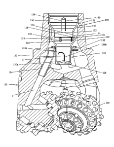
[0018] Fig. 4 a cross-sectional view of an embodiment of an air/water
separator
installed in an embodiment of a rotary drill bit;
[00191 Fig. 5 represents a perspective view of the embodiment of the air/water
separator shown in Fig. 4 including a back flow valve assembly;
[0020] Fig. 6 represents a close-up view of the boundary between a first
funnel and a
second funnel of the embodiment of the air/water separator shown in Fig. 4;
[0021] Fig. 7 represents a perspective view of a portion of an embodiment of a
separation ring and air-tube;
[0022] Fig. 8 represents a perspective view of an embodiment of a joint
between a drill
bit and a drill string;
[0023] Fig. 9 represents a cross-sectional view of a connection between an
embodiment
of an air/water separator and a drill string; and
[0024] Fig. 10 represents a cross-sectional view of a drill bit including an
embodiment of
an air/water separator and a portion of a drill string,
CA 02967400 2017-05-10
WO 2016/089652
PCT/US2015/062178
Detailed description of embodiments of the invention
[0025] Embodiments of the invention provide a unique, simple and elegant
solution to
problems related to existing air/water separators. The air/water separator may
include no moving parts, such as hinges or springs. Additionally, the
air/water
separator may generate a much lower back pressure than currently utilized
structures.
[0026] Another benefit of embodiments of the air/water separator is that it
may be
inserted into existing bit structures without requiring any modification to
the bit
structure other than machining the bore of the pin connection. Also, the
structure of
embodiments of the air/water separator permits pressure in the bit to be tuned
by
adjusting size of the bit nozzles, providing a much better control of the flow
of air and
water through the bit. Furthermore, embodiments of the air/water separator may
be
scaled up or scaled down for various sized bits.
[0027] In its simplest form, an air/water separator according to the invention
typically
includes two at least partially nested hollow members. The hollow members are
arranged such that a lower end of an upper of the hollow members at least
partially
extends into an upper end of a lower of the hollow members such that the lower
end of
the upper of the hollow members is not coplanar with the upper end of a lower
of the
hollow members. Additionally, in the region with the two hollow members
overlap, a
gap is present between the outer wall of the upper hollow member and the inner
wall of
the lower hollow member.
[0028] The inner surfaces of the hollow members may have a variety of
contours. For
6
CA 02967400 2017-05-10
WO 2016/089652
PCT/US2015/062178
example, the inner surfaces may be substantially cylindrical. Along these
lines, the
inner surfaces may be cylindrical or vary within a few degrees of being
perfectly
cylindrical. The inner surfaces may also be frustoconical, up to an angle of
about 700.
According to other examples, the hollow members have inner surfaces contoured
as
funnels.
[0029] While the contour of the inner surfaces of the hollow members may be
the same
over their entire areas, the inner surfaces may have a plurality of contours.
Regions of
different contours may meet at a sharp, defined angle. The contour of the
inner surface
of the hollow members may also gradually curve between two regions having
different
contours. Additionally, regions of the inner surfaces of the may include flat
and/or
curved sections. For example, a hollow member having a conical inner surface
may be
flat. Alternatively, the inner surface could curve inwardly or outwardly. It
is not
necessary that the upper and lower hollow members have the same contour; the
contours of the inner surfaces may be different.
[0030] The air/water separator may include more than two hollow members or
more
than one pair of hollow members. It is possible that any combination of hollow
members may be utilized. For example, a funnel may be utilized with a
converging
cylinder. While the discussion below relates to one particular embodiment
including
two hollow members that are funnels, this is meant to be illustrative. Other
hollow
members having different shapes and contours of inner surfaces could be
substituted
for the funnel(s).
[0031] Regardless of the shape of the hollow members, the flow path, or first
flow path,
7
CA 02967400 2017-05-10
WO 2016/089652
PCT/US2015/062178
between the exit of the first, or upper, hollow member and entrance of the
second, or
lower, hollow member may about 10% to about 40% of the smallest flow area of
the
first hollow member. Typically, the smallest flow area is present at the exit
of the first
hollow member.
[0032] A second flow path out of the base of the second hollow member may be
about
60% to about 90% of smallest flow area of the first hollow member. Typically,
the inlet
of the second hollow member is larger than the exit of the first hollow
member.
Additionally, the minimum flow area of the second hollow member is typically
less than
the minimum flow area of the first hollow member. Further, the flow area of
the first
flow path is typically larger than combined flow area to the bearings of the
bit in which
the air/water separator is incorporated and the flow area of the second flow
path is
typically larger than combined flow area through the nozzles of the bit in
which the
air/water separator is incorporated. A hollow member that is a funnel may have
a
converging angle that may be from about 0 , in other words, cylindrical, to
about 700
depending on the embodiment or bit size. Any of these dimensions, shapes,
angles and
other parameters of the air/water separator may vary depending upon the size
of the
bit, flow rate, and other factors.
[0033] Fig. 4 shows an embodiment of an air/water separator 100 including a
first
funnel 102 and a second funnel 104 installed in a drill bit 101 including
three cones 103.
Although a tri-cone bit is illustrated and described herein, the air/water
separator may
be utilized with any bit, rotary, non-rotary or otherwise. The air/water
separator is
particularly useful with bits that include bearings to help divert water
and/or debris
away from the bearings. Modifications may need to be made to the air/water
separator
8
CA 02967400 2017-05-10
WO 2016/089652
PCT/US2015/062178
and/or the bit to make the air/water separator and bit structures compatible.
It may
also be possible to incorporate the air/water separator elsewhere in a
drilling assembly
structure.
[0034] Typically, the first funnel 102 has an entry 106 having a larger inner
diameter
than an inner diameter of the entry of the second funnel 104. Similarly, the
first funnel
typically has an exit 108 having a larger inner diameter than an exit 112 of
the second
funnel 104. The diameter of the first funnel 102 and second funnel 104 may
depend at
least in part upon the size of the drill bit into which the air/water
separator is installed.
[0035] The first funnel 102 and the second funnel 104 may have any suitable
interior
contour. The interior contour of the first funnel 102 and/or the second funnel
104 may
vary depending at least in part upon a desired increase in velocity in air and
water
flowing through each funnel. The interior contour of the first funnel and the
second
funnel may vary from being almost cylindrical, with little variation in the
contour
among the various sections of the interior surface of the funnel(s). The first
funnel 102
and the second funnel 104 of the embodiment shown in Fig. 4 each include an
entry
section, an inclined section and an exit section. The exit section of each
funnel is
generally cylindrical but may vary within some degrees of cylindrical. The
reduced
cross-sectional area reduces the flow area and accelerates the flow through
the reduced
flow area.
[0036] The first funnel includes an opening 106 and an exit 108. Similarly,
the second
funnel includes an opening 110 and an exit 112. As shown in Fig. 4, the exit
108 of the
first funnel 102 is located within the entry 110 of the second funnel 104 such
that the
9
CA 02967400 2017-05-10
WO 2016/089652
PCT/US2015/062178
exit 108 of the first funnel 102 is not coplanar with the entry 110 of the
second funnel
104. The distance that the first funnel extends into the second funnel may
vary
depending upon the embodiment.
[0037] The arrangement of the first funnel 102 and the second funnel 104
creates a flow
pattern that extends down through the interior 116 of the first funnel 102,
across the
exit 108 of the first funnel 102, up through the space between the interior
118 of the
second funnel 104 and exterior 120 of the first funnel 102, across the entry
114 of the
second funnel 104 and down the exterior 122 of the second funnel 104. Thus,
the flow
pattern typically includes two 180 turns. Fig. 6 illustrates the flow path
for the
embodiment shown in Fig. 4. As discussed in greater detail below, an effect of
such a
flow path may be to separate water, drops of which cannot make such turns,
from air,
which can make such turns.
[0038] The first funnel 102 and the second funnel 104 may be interconnected in
a
variety of ways. For example, one or more elements may be arranged in the
interior of
the second funnel. Along these lines, a plurality of stops 124 may be attached
or formed
on the inner surface 118 of the second funnel. The first funnel 102 may rest
on the rest
on the stops 124. The stops and end of the first funnel may engage each other
so as to
position the first funnel 102 and second funnel 104 with respect to each other
and
retain them in position.
[0039] Additionally, or alternatively, a plurality of ribs 126 may be attached
to first
funnel 102 and/or the second funnel 104. The ribs and stops may be the same or
separate structures. The ribs 126 may position the first funnel 102 and second
funnel
CA 02967400 2017-05-10
WO 2016/089652
PCT/US2015/062178
104 with respect to each other. The ribs 126 may also strengthen the combined
first
funnel 102 and second funnel 104. The size and number of ribs 126 may vary,
depending upon the embodiment. Since the ribs 126 connect the first funnel 102
and
second funnel 104, the first flow path 131 between the first funnel 102 and
the second
funnel 104 is not present where a rib is present. Therefore, the size and
number of ribs
126 may vary depending upon how much flow through the first flow path is
desired.
Embodiments of ribs 126 are shown in Fig. 4 in cross-section and in Fig. 5 in
perspective
views.
[0040] The first flow path extends between the first funnel 102 and the second
funnel
104. A second flow path extends from the first funnel 102 through the second
funnel
104. The exit 112 of the second funnel 104 may be closed by a closure 128.
Additionally, the lower portion of the second funnel 104 may include at least
one exit
window 130. The upper surface of the closure 128 may have a conical contour to
direct
flow to the window(s) 130. The upper surface of the closure 128 could have
other
contours, such as spherical, planar or include a plurality of regions having
different
contours. A non-planar closure, such as the conical closure shown in Fig. 4,
may help to
reduce recirculation in the second funnel 104 and also direct flow toward the
at least
one window.
[0041]As described above, the second funnel 104 may include at least one
window 130.
Typically, the second funnel includes three windows if utilized with a tri-
cone bit. Each
window may be arranged so that it directs flow toward the nozzles of the bit.
[0042] The at least one window 130 located at or in the vicinity of the base
112 of the
11
CA 02967400 2017-05-10
WO 2016/089652
PCT/US2015/062178
second funnel 104 may have any desired size and shape. The size and/or shape
may
vary depending upon the desired flow through the second funnel 104 and bit in
which
the air/water separator is incorporated. The embodiment shown in Figs. 4 and 5
includes three windows, two of which are shown at least partially. The base
130a of the
windows 130 is defined by the contour of the exit 112 of the second funnel 104
and
closure 128. The embodiments of the windows 130 shown in Figs. 4 and 5 have
vertical
side walls 130b and an arched top 130c. However, the window(s) may have other
shapes.
[0043] Some embodiments may not include windows in the second hollow member,
or
funnel in this embodiment Such embodiments would not include a closure at the
base
of the second hollow member. Rather, the second flow path would extend down
through the bottom of the second hollow member.
[0044] The air/water separator may include additional flow-directing elements.
For
example, the embodiment shown in Figs. 4 and 5 may include a separating ring
132 that
helps to direct flow from the first flow path to bearings of a bit with which
the air/water
separator is utilized. The separating ring may also help to isolate the first
flow path
from the second flow path. The separating ring may be made of a single unitary
ring.
Alternatively, the separating ring may include a plurality of ring elements
jointed
together to form the separating ring 132. For example, Figs. 4 and 5
illustrate a
separating ring including a plurality of ring elements. Segments of ring 132
may be
integral with air-tubes 134 or separate pieces, both methods being joined to
form a ring.
[0045]At least one air-tube 134 may extend from the separating ring 132 toward
12
CA 02967400 2017-05-10
WO 2016/089652
PCT/US2015/062178
bearings of a bit with which the air/water separator 100 is utilized.
Typically, the
air/water separator 100 includes three air-tubes 134 for use with a tri-cone
bit. The
air-tube(s) may be formed integral with or attached to one or more separating
ring
elements. One air-tube and integral separating ring element is shown in Fig.
7. The
embodiments shown in Figs. 4 and 5 include non-integral air-tubes and
separating ring
elements. Fig. 8 illustrates three of the integral air-tube and separating
ring elements
installed in a bit.
[0046] According to the embodiment shown in Figs. 4 and 5, each air-tube is
formed
with or connected to a separating ring element. The separating ring elements
may be
attached to the air-tubes to form a continuous ring between the air-tubes.
According to
this embodiment, the separating ring elements attached to the air-tubes may be
connected by bolts and nuts. The separating ring elements could also be joined
by
adhesive, welding, or utilizing other techniques.
[0047] The separating ring 132 may be attached to the interior surface of a
bit with
which the air/water separator is utilized. Alternatively, the separating ring
132 could
rest on one or more supports within the bit, such as attached to an inside
surface of the
bit. If the separating ring 132 is attached to the bit, it could be secured
with adhesive or
welding or any other suitable technique.
[0048] Figs. 7 and 8 provide two views how the air-tubes may include a metal
tube with
a partial ring welded to the tube. Once installed in the bit, the partial
rings could be
welded together rather than bolted together as with the embodiment shown in
Figs. 4
and S. No matter what material is used for the air-tubes and ring, the ring
typically
13
CA 02967400 2017-05-10
WO 2016/089652
PCT/US2015/062178
cannot be installed as one piece. This is because the ring typically has a
larger diameter
than the bore through the pin connection of the bit. As a result, the ring is
typically
divided into three parts, with one part attached to each air-tube. Other
embodiments
may include a flexible one piece ring.
[0049] It may simplify introducing and securing the separating ring and air-
tube(s) in
the bit if the separating ring includes a plurality of pieces. The separating
ring pieces
and air-tubes may be separately introduced into the bit and positioned as
desired. The
separating ring pieces may then be secured to the bit. The second funnel 104
may also
be secured to the separating ring/separating ring pieces also.
[0050] The funnels, air-tube(s) and retaining ring and any other parts of the
air/water
separator may be made of a variety of materials. For example, the air-tubes
and
retaining ring may be made of plastic, including thermoplastic composites.
According to
such embodiments, funnels, air-tube(s) and retaining ring and any other parts
of the
air/water separator may be produced with 3-D printing. The parts could also be
injection molded. The air-tube(s) and/or retaining ring may be made of metal.
The
flexibility of materials and methods for manufacturing the air/water separator
is due at
least in part from the fact that the air/water separator may have no moving
parts.
[0051] The separating ring separates the first flow, which may be considered
the "dry"
flow, from the second flow, which may be considered the "wet" flow. While
spaces
between the separating ring and the second funnel and/or bit interior wall may
be
made air tight, typically, they are not. This is because a small amount of
mixing of the
flows due to the spaces not being air tight does not cause separating
efficiency losses
14
CA 02967400 2017-05-10
WO 2016/089652
PCT/US2015/062178
sufficient to counter the time and cost associated with making the spaces air
tight.
Rather, the parts are typically designed with enough clearance to be assembled
within
the bit and to accommodate pressure spikes in either the wet zone or dry zone
with a
certain clearance between the parts allowing a small amount of communication
between them. The small communication between areas also allows for the use of
less
rigid parts because pressure spikes between the dry and wet zones can equalize
rather
than push through to the lower pressure region damaging features of the
air/water
separator.
[0052] As shown in Fig. 4, a back flow valve assembly 136 may be arranged at
the entry
106 to the first funnel 102. The back flow valve assembly 136 shown in Figs. 4-
6
includes a spring-loaded valve including two valve flaps 138 and 140. The
springs bias
the valve flaps closed with sufficient force such that if the flow of air
and/or water is
turned off or reduced below a certain value, the valve flaps will shut. The
back flow
valve closes if air circulation is lost while drilling or coming out of the
hole. The back
flow valve maintains a sudden onset of cuttings settling in the hole from
coming back
inside the bit and plugging airflow passages in the nozzles and bearings.
[0053] The air/water separator may be inserted into a pin connection of a
rotary bit.
The bore of a rotary bit that accepts air/water separator may also receive the
back flow
valve. Typically, unlike known devices, the air/water separator does not
combine
air/water separator functionality with back flow valve functionality. The two
may
remain as separate components available independently or paired together. This
may
increase configuration options plus greatly simplify the geometry of the
air/water
separator. Since the air/water separator typically has no moving parts, it is
particularly
CA 02967400 2017-05-10
WO 2016/089652
PCT/US2015/062178
suited for the arduous environment for rock bits. This may also further
simplify
installing the air/water separator as a drop-in component in rotary bits.
Extreme
vibrations during drilling can cause pieces to vibrate apart during operation.
[0054] The air/water separator may utilize a machined bore in a pin connection
to
ensure proper clearance around the second funnel for dry air flow and between
the
retaining ring and the bore to control communication between the dry and wet
zones.
Fig. 9 illustrates a "universal bit bore" 200 that may receive the air/water
separator, air-
tubes and the back flow valve.
[0055] The air/water separator may be arranged such that an outer surface of
the upper
funnel engages an inner surface of the bit bore, as shown in Fig. 4.
Additionally or
alternatively, the base of the lower funnel may rest on a surface within the
bit bore. The
air-tube(s) extend into and/or receive the air-tubes of the bit, as also shown
in Fig. 4.
The air/water separator may be attached to the bit, such as with a snap ring
or other
similar structure. Any other attachment technique could also be utilized, such
as
welding, adhesive or other mechanical or other techniques. The outer surface
or one or
more of the funnels may include a tab. One or more grooves having a shape
complementary to the tab may be arranged on an inner surface of the bit bore.
The
tab(s) may engage the groove(s) when the air/water separator is arranged in
the bit
bore. During operation, the tab(s) and groove(s) may help to prevent the
air/water
separator from rotating.
[0056] The air/water separator includes the first flow path around the exit of
the first
funnel and entry of the second funnel. This first flow path may actually
include two
16
CA 02967400 2017-05-10
WO 2016/089652
PCT/US2015/062178
1800 turns. The flow through the first flow path may be accelerated through
the first
funnel. Water droplets in the flow are too heavy to make the turns between the
first
funnel and the second funnel, especially at higher velocity. The air/water
separator
may be utilized with a variety of bits, bit sizes and flow rates. In the
embodiment shown
in Fig. 4, the air/water separator may be utilized with a flow rate of about
1900
standard cubic feet per minute (SCFM) to about 3800 SCFM.
[0057] As shown in Fig. 6, the bottom of the first funnel and the top of the
second funnel
overlap axially. If they do not overlap axially and there is direct flow
between the first
and second funnels to the dry area, then the water will follow the air. The
water
droplets may fan out upon exiting the first funnel and cylinder. What
separates the
water is that it cannot make the first or second U-turns so it must keep
proceeding
down the walls of the second funnel. Fig. 10 illustrates the embodiment of the
air/water
separator shown in Fig. 4 installed in a bit and attached to a drill string
202.
[0058] The air/water separator may also act to help prevent debris, which may
include
anything other than air, such as rubber from hoses, from entering the drill
pipe and the
air tubes. For example, air passing through the first flow passage must
negotiate the
passage between the funnels. Debris, and large debris in particular, typically
will not
make the turns between the ends and openings of the funnels, similar to water.
This
will act to prevent debris from passing further through the air/water
separators.
Additionally, air passing out of the base of the second funnel will need to
pass around
the separating ring to get to the air tubes. This will also help to prevent
debris from
reaching the air tubes.
17
CA 02967400 2017-05-10
WO 2016/089652
PCT/US2015/062178
[0059] Typically, air tubes are screened to help prevent debris from entering
them.
Along these lines, the air tube entrances may be slotted, perforated, or
otherwise
screened to help prevent flow of debris therein. A benefit of the air/water
separator is
to help prevent debris from reaching the air tubes. As a result, the air tubes
may not
need any screening structure.
[0060] A method for drilling may include providing an air/water separator. The
air/water separator may be installed in a drill bit. A backflow valve may also
be
installed it the bit. The bit may be attached to a drill string and drilling
motion applied
to the bit, Drill fluid including a combination of air and water flow into the
drill string.
The air and water may be introduced into the drill bit. The air and water is
received in
an air/water separator arranged in the pin connection, thereby directing the
air and
water into a first hollow member and through a second hollow member, wherein
an exit
of the first funnel extends into an opening of the second hollow member such
that the
exit of the first hollow member axially overlaps the opening of the second
hollow
member. A substantial portion of the air is directed through a first flow path
from the
interior of the first hollow member to the outside of the second hollow member
including two turns about the exit of the first hollow member and opening of
the second
hollow member, A substantial portion of the water flows through a second flow
path
from the first hollow member through the second hollow member.
[0061] The reduced flow areas through the first funnel, between the first and
second
funnels and through the windows of the second funnel should remain larger than
the
largest combination of flow areas exiting the bit through the nozzles and
bearings. As a
result, the bit pressure may be regulated by a typical technique of changing
nozzle sizes.
18
CA 02967400 2017-05-10
WO 2016/089652
PCT/US2015/062178
If a combined flow area in the air/water separator is smaller than the largest
combination of flow areas exiting the bit through the nozzles and bearings, it
will
determine bit pressure and changing nozzle sizes will not change the bit
pressure, until
the nozzle size decreased to the point where the bit exit flows are less than
the smallest
combined flow area in the air/water separator.
[0062] The second funnel typically has a smaller flow area than the first
funnel so that
air is pushed up and around into the dry zone to supply dry air to the
bearings. If the
first and second funnels have the same flow area, or if the second funnel flow
area is
larger, then enough flow will not be forced into the dry zone and there will
be
insufficient air for bearing cooling and cleaning. The second funnel and
cylinder should
be sized so that the second funnel forces enough air into the dry zone without
causing
increased back pressure.
[0063] At certain times it is necessary to inject larger volumes of water
during rotary
drilling. This typically does not affect the efficiency of the separator since
it is all
accelerated through the upper funnel and the lower funnel. Differences between
the
air/water separator and known devices include that the air/water separator may
control back pressure with the flow areas through and around the funnels
rather than
created by vanes at flat angles and a center dome as in known devices.
Additionally, the
air/water separator may work over a very wide range of air flow rates. A dust
arresting
multi-purpose adapter (DAMPA) sub must be tuned for specific air volumes, bits
and
drills. The air/water separator may rely on accelerating the water flow to a
higher,
straight line velocity through the center so it cannot U-turn twice into the
outer dry area
rather than centrifuging the water to the outer perimeter like know devices.
The
19
CA 02967400 2017-05-10
WO 2016/089652
PCT/US2015/062178
air/water separator may be held in place from rotating. No forces are trying
to spin the
part, but the water windows in the bottom cylinder need to stay aligned with
the
nozzles for optimal flow through the bit.
[0064] The foregoing description of the invention illustrates and describes
the present
invention. Additionally, the disclosure shows and describes only the preferred
embodiments of the invention, but as aforementioned, it is to be understood
that the
invention is capable of use in various other combinations, modifications, and
environments and is capable of changes or modifications within the scope of
the
inventive concept as expressed herein, commensurate with the above teachings,
and/or
the skill or knowledge of the relevant art. The embodiments described
hereinabove are
further intended to explain best modes known of practicing the invention and
to enable
others skilled in the art to utilize the invention in such, or other,
embodiments and with
the various modifications required by the particular applications or uses of
the
invention. Accordingly, the description is not intended to limit the invention
to the form
disclosed herein. Also, it is intended that the appended claims be construed
to include
alternative embodiments.