Note: Descriptions are shown in the official language in which they were submitted.
CA 02967639 2017-05-02
WO 2016/071940 PCT/1T2015/000270
Page 1 of 10
1 "AUTOMATED SYSTEM FOR DRAINING, CLEANING AND SANITIZING OF
PORTABLE TOILET SEWAGE HOLDING TANKS USED IN RECREATIONAL
VEHICLES SUCH AS CAMPERS, CARAVANS, MOTORHOMES AND BOATS"
TECHNICAL FIELD
Means of transport such as recreational campers, boats, motor homes, etc.,
come equipped
with on-board bathrooms with removable sewage tanks for the disposal of sewage
from the
use of the toilets.
This presupposes the need for a regular and frequent emptying of the same, in
itself an
unpleasant operation, given the need to comply with applicable environmental
protection
regulations that prohibit the disposal of sewage anywhere but in properly
equipped sites.
BACKGROUND ART:
To the current state of the Art, (ref. patents. MI2013U000104; DE 203 08 586
U1) this
emptying operation is performed manually or semi-automatically with the
following
difficulties and problems:
a) there are a variety of manufacturers and models of sewage tanks on the
market, such as
"Thetford" and "Dometic" (by way of example only) and the differences are not
taken into
consideration by the current state of the Art;
b) human intervention for the opening of the cap, the washing of the cap, the
opening and
closure of the slide and vent knob, and final closing of the cap is still
required, resulting in
an unpleasant and unhygienic experience for the person who performs this
operations as
well as raising health risk due to the promiscuity of the sites and the
probable proliferation
of bacteria;
c) Risk of contamination and polution (both bacterial and olfactory) caused by
lack of a
rinsing system within the machine itself, following its use by the previous
user.
DISCLOSURE OF INVENTION:
The aim of the system, referred to in the present invention, is to create a
machine capable
of recognizing the type of tank inserted and exclude manual operations of any
nature
COMPLETELY thus creating a FULLY AUTOMATED machine with perfect respect of
personal and environmental hygiene, as it is directly connected to the sewage
system or to
CA 02967639 2017-05-02
WO 2016/071940 PCT/1T2015/000270
Page 2 of 10
1 a
larger storage tank should the machine be installed in isolated transit zones
such as
remote parking areas along the motorway network or ports, with the added
benefit of
discouraging illegal emptying into the environment.
Another purpose of this machine is to ensure the internal and external
sanitizing of the
sewage holding tanks, in complete safety, so that even less experienced users
are able to
use the machine, and products of commonly commercial availability are supplied
in order
to ensure an efficient and competitive economic return.
BRIEF DESCRIPTION OF DRAWINGS:
The operational process of the machine and its advantages will become more
apparent as
they are highlighted through the description of the invention and illustrated
by means of
non-exhaustive and / or limitative examples in the accompanying drawings:
= Page 1/11 Figure 1.1 depicts the insertion of the WC tank (A) in the
machine on the
insertion slide (B) positioned within a rotating platform (C) through a
sliding entry
door; Figure 1.2 is an exploded view of the WC tank (A) in which the pour-out
spout (G), the closure cap (J), a cover slide (L) and opening blade (R) are
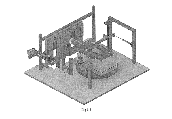
identified. Figure 1.3 depicts the positioning of all the new parts in
relation to each
other.
= Page 2/11 Figure 2.1 depicts, in perspective view, the position within
the machine
of the mechanism to rotate the pour-out spout (G) and Fig. 2.2 depicts in
plan, the
procedure of rotation of the pour-out spout(G) which in brought about by the
rotation of the tank (A) on the rotating platform (C) and a lever (F) which
forces the
rotation of the pour-out spout (G); Figure 2.3 illustrates the same procedure.
= Page 3/11 Fig. 3.1 depicts, in perspective view, the position with
respect to the
central rotating platform of the apparatus (H) used for the unscrewing of the
closure
cap (J) of the pour-out spout (G) of the sewage tank(A);
= Page 3/11 Fig. 3.2 depicts the process of approach of the device (H) to
the cap (J),
by extension of a mechanical arm, the unscrewing of the cap (J) which closes
the
pour-out spout (G), and withdrawal of the device (H) now retaining the cap (J)
within it grip;
= Page 3/11 Fig. 3.3 illustrates the cylinder's internal strips as they are
situated on the
inside of the cylindrical device; Fig. 3.4 gives an overall view of the
cylindrical
CA 02967639 2017-05-02
WO 2016/071940 PCT/1T2015/000270
Page 3 of 10
1 device mounted on a mechanical arm.
= Page 4/11 Fig. 4.1 illustrates the position inside the machine, with
respect to the
central rotating platform, of the apparatus (I) that cleans and sanitizes the
closure
cap (J) of the pour-out spout (G) of the tank (A);
= Figure 4.2
depicts the process of cleaning the cap (J) once it has been unscrewed
from the pour-out spout (G) of the tank (A); the mechanical arm of device (H)
swivels to align and insert the cap into apparatus (i).
= Fig. 4.3 illustrates the internal brush structure of apparatus (i); Fig.
4.4 illustrates
the alignment of device (H) with apparatus (i).
= Page 5/11 Fig. 5.1 illustrates the position of interface masks (K) inside
the machine
in relation to the rotating platform (C ) and WC sewage tank (A); Figure 5.2
illustrates the lateral movement of the masks to align the mask that
corresponds to
the model of tank inserted; Fig. 5.3 illustrates details of the interface mask
(K) with
shutter and latch;
= Page 6/11 Fig.6.1 illustrates the pivoting of the central container of the
rotating
platform (C ) enclosing the tank (A); Figure 6.2 depicts a sequencial view of
the
lifting of the central container and tank, the coupling of the tank with the
interface
masks (K) and the draining of the tank through its pour-out spout (G);
= Page 7/11 Fig. 7.1 depicts in an elevation plan view, the internal
washing pressure
lance (M) that is inserted into the opening of the tank and the sanitizing
process by
means of a metering valve with detergents ; Fig. 7.2 is a plan view which
shows the
return of the tank to its horizontal plane;
= Page 8/11 Fig. 8.1 illustrates the positioning of the tank with respect
to
injector/nozzle (N) for reloading of toilet fluids; Figure 8.2 depicts the
process of
rotating and filling the holding tank (A) with sanitation fluids;
= Page 9/11 depicts, in plan view, the re-screwing of the now sanitized
closure cap (J)
to the pour-out spout (G)
= Page 10/11 Figure 10.1 illustrates the position of the shaped lever (0)
for the
closing of the pour-out spout (G); Figure 10.2 shows the static model of the
template block shaped lever (0); Figure 10.3 depicts in plan view, the
pivoting of
the pour-out spout (G) forced to return to its home position due to the
leverage
applied by this block (0) during rotation of the platform (C).
CA 02967639 2017-05-02
WO 2016/071940 PCT/1T2015/000270
Page 4 of 10
1 Page 11/11 depicts the process by which the outside of tank (A) is
washed by
rotating brushes (P) and dried through vertical and horizonal air blades to be
returned to the user;
BEST MODE FOR CARRYING OUT THE INVENTION:
With particular reference to the alphabetic indicators of the above figures,
the machine,
subject of the invention, consists of a parallelepiped upright casing with an
opening for the
insertion of a sewage-holding tank (A), through a sliding safety door
activated by a
payment system.
The sewage holding tank (A) is placed on a sliding plate (B) which is
positioned to assist
horizontal movement of the tank to its correct position within the container /
cradle as
shown in Fig. 1.1
After this insertion a detection systems recognizes both the correct insertion
of the tank and
the type of the tank inserted. A process management system positions the
correspondant
mask and adapts the work plane according to the type of tank inserted. The
safety door
closes and the process initiates.
The platform (C) rotates anticlockwise on a vertical axis until it reaches a
first control
point where it awaits the positioning of a shaped lever (F). An actuator
inserts this lever
between the body of the tank (A) and the pour-out spout (G). Through the
movement of
platform (C) in the opposite direction the lever forces the pour-out spout (G)
to pivot to
perpendicular with respect to the tank.
A subsequent anticlockwise rotation of the platform (C) to a second control
point aligns
the tank to cylindrical device (H) on the extremtiy of a mechanical arm. This
arm extends
the device (H) to grip the closing cap (J) on the pour-out spout (G) Once the
cap has been
secured in the device (H), this latter rotates to unscrew the cap. The
mecahnical arm
retreats, withdrawing the cap from the pour-out spout, and rotates to align
the cap with its
cleaning mechanism (i) to be once washed and sanitized;
The system retains the cap and inserts it in a cylindrical container (I) the
circumference and
centre of which is covered with brushes. The rotational movement of the
mechanical arm
rotates the cap on its axis against the brushes, at the same time detergent
and water are
sprayed into the inside of the cylinder (I).
A further clockwise rotation of the platform (C ) aligns the holding tank (A)
with the
CA 02967639 2017-05-02
WO 2016/071940 PCT/1T2015/000270
Page 5 of 10
1 previously selected mask (K). The container / cradle of the rotating
platform (C ) is tilted
on its vertical axis. The tank starts emptying its contents due to
gravitational fall.
Once the holding tank is vertical it couples with the interface mask (K). The
sliding lid (L)
which connects the tank and the toilet basin itself is opened together with
the underlying
opening blade (R), in order to allow a lance (M) to be inserted into the tank.
This lance
(M) has rotating nozzles at it extremity which start the internal washing
cycle by spraying
pressurized water and sanitizing detergent into the tank.
A reverse procedure is activated following the washing process in order to
bring the
holding tank (A) back to its horizontal position and allows the reloading of
the tank with
sanitizing fluids by inserting a dosing injector (N) through the pour-out
spout;
The tank, through the anti-clockwise rotation of platform (C ), is returned to
the automatic
system (that by reversing the previously described UN-screwing process )
correctly RE-
screws and tightens the now sanitized closure cap (J) to the pour-out spout
(G).
A subsequent anti-clockwise rotation of platform (C ) forces the pour-out
spout against
template block (0) and levers it back to its home position against the side of
the tank;
Two motors push the plate (B), holding the tank (A) within the container /
cradle, into
position between rotating brushes (P) under a spray of water and detergents to
ensure its
external cleanliness. The tank is subsequently dried by pulling the plate and
tank through
vertical air blades.
The platform rotates the tank to home position and the security latch holding
the tank to the
sliding plate is released.
An indicator signals the end of the process and the security doors open for
the use to
withdraw the holding tank.
Between one wash cycle and another the machine automatically performs its own
flushing
and rinsing with biodegradable sanitizing products in order to ensure perfect
hygiene for
each cycle.
The invention is equipped with safety mechanisms so as to impede accidental
opening of
the machine during its operating cycle; it is equipped with UPS and an
emergency water
tank capable of reaching the end of a processing cycle even in case of
interruption of the
electrical or water supply.
From a constructive point of view the machine is preferably made of metallic
materials
protected by weather resistant paint or polymer or stainless steel and in any
case must
CA 02967639 2017-05-02
WO 2016/071940
PCT/1T2015/000270
Page 6 of 10
1 comply with regulations.
All active parts of the machine (motors, actuators, sensors, etc.), and the
entire operating
cycle runs on low voltage, up to 24 volts derived from a transformer input 220
AC single
phase output 24 volts DC; materials used: ip 66.
10