Note: Descriptions are shown in the official language in which they were submitted.
CA 02967713 2017-05-12
1
Method and device for coating a metal strip
The invention relates to a method and a device for coating a metal strip with
an initially still
liquid coating material, for example zinc. The method and device serve for, in
particular, hot-
dip galvanising of the metal strip.
Devices of that kind for coating a metal strip are basically known in the
prior art thus, for
example, from DE 10 2009 051 932 Al. In concrete terms, this specification
discloses a
coating container filled with a liquid coating material. For coating, the
metal strip is conducted
through the container with the coating material. After leaving the coating
container the metal
strip runs through a blowing device, which is arranged above the coating
container, for
blowing excess parts of the still liquid coating material off the surface of
the metal strip. An
electromagnetic stabilising device for stabilising the metal strip after
leaving the coating
container and the blowing device is arranged above the blowing device and is
supported by
the blowing device. The electromagnetic stabilising device has the effect, in
particular, that
the strip is held centrally in a centre plane of the overall device and that
oscillations of the
metal strip during transit through the coating container and the blowing
device are prevented
or at least reduced.
Each of the blowing device and the electromagnetic stabilising device has a
respective slot
through which the metal strip is guided. In order to achieve a uniform
thickness or thickness
distribution of the coating material on the upper side and lower side of the
metal strip it is
essential for the metal strip to run in a predetermined target centre position
through the slot of
the blowing device. Only then is it guaranteed that the action of the blowing
nozzles of the
blowing device on the upper side and lower side of the metal strip is the same
and a desired
uniform thickness distribution of the coating material on the metal strip
results.
The target centre position is defined by, in particular, a preferably uniform
spacing of the wide
sides and the narrow sides of the metal strip from the oppositely disposed
nozzles of the
blowing device and, in particular, by the fact that the metal strip is not
inclined, twisted or too-
strongly curved relative to the longitudinal orientation of the slot or the
nozzles.
AMENDED SHEET
CA 02967713 2017-05-12
2
However, in practice it can happen that the metal strip after leaving the
coating container is
strongly curved. Such a curvature is, as stated, undesirable particularly for
passage through
the blowing device. Traditionally, the curvature is therefore counteracted by
a correction roller
being adjusted against the metal strip before the metal strip enters the
blowing device.
However, this has the disadvantage that as a consequence the actual position
by which the
metal strip runs through the slot of the blowing device can depart from the
target centre
position, which can lead to the above-described problem of a non-uniform
thickness
distribution of the coating.
German published specification DE 10 2007 042 897 Al discloses a method with a
device for
coating a metal strip with a coating material, for example zinc. For this
purpose, the metal
strip is conducted through a coating container filled with the liquid coating
material, in which
case the coating material adheres to the surface of the metal strip. After
leaving the coating
container the metal strip runs through a slot of a blowing device which serves
the purpose of
blowing excess parts of the still liquid coating material off the surface of
the metal strip. In
addition, a curvature sensor is provided for detecting the actual curvature of
the metal strip
after leaving the coating container. Insofar as the detected actual curvature
exceeds a
predetermined permissible curvature threshold value, a correction roller is
adjusted against
the metal strip in order to smooth this. Control of the blowing device is also
disclosed.
Specification DE 43 00 868 Cl teaches positioning of the blowing device with
the help of
adjusting drives so that the spacing between nozzle gap and strip surface
remains constant.
The corresponding control or regulation of the position of the blowing device
is carried out in
dependence on the actual position of the metal strip, which is continuously
detected by a
separate measuring device.
WO 94/02658 Al teaches provision at least implicitly of a curvature sensor for
detecting the
curvature of the metal strip above the blowing device. If excessive curvature
is ascertained so
that there is a possible risk of contact between strip and blowing device the
blowing device is
moved transversely to the plane of the metal strip until a minimum spacing
between metal
strip and blowing device is reinstated over the entire width of the metal
strip.
AMENDED SHEET
84004200
3
JP 2003 113460 A provides a so-called displacement sensor (numerical value),
which is arranged in the electromagnetic stabilising device and which is
formed to
detect the state of curvature or the amount of eccentricity of the metal strip
in the slot
of the electromagnetic stabilising device. Depending on the amount of
eccentricity of
the metal strip current is supplied to the electromagnets of the
electromagnetic
stabilising device so as to generate magnetic forces on the metal strip of
such a kind
that the curvature and the path position of the metal strip are corrected. A
stabilising
roller and the correction roller are controlled or positioned in the metal
bath with the
help of a process control device in dependence on the output values. In
addition,
stripper nozzles are controlled and positioned in correspondence with a
mathematically determined eccentricity index and, in particular, so that the
index or
eccentricity of the metal strip lies within or below a predetermined threshold
value.
The stripper nozzles and the electromagnetic units or the electromagnetic
stabilising
device are respectively moved in parallel by the same amount.
The invention has the object of developing a known method and a known device,
of
the kind stated in the introduction, for coating a metal strip in such a way
that non-
uniform thickness distribution of the coating on the metal strip is prevented
by way of
adjustment of the correction roller.
In some embodiments of the invention, there is provided a method of coating a
metal
strip with a coating material, wherein the method comprises the following
steps:
conducting the metal strip to be coated through a coating container filled
with the
liquid coating material, wherein the coating material adheres to the surface
of the
metal strip to be coated; conducting the coated metal strip through a slot of
a blowing
device, which is downstream of the coating container in the transport
direction of the
metal strip, for blowing excess parts of the still liquid coating material off
the surface
of the metal strip; detecting the actual curvature of the metal strip after
leaving the
coating container; adjusting a correction roller, which is arranged within the
coating
container, against the metal strip for smoothing the metal strip when the
amount of
the actual curvature exceeds a predetermined permissible curvature threshold
value,
CA 2967713 2018-07-24
B4004200
4
wherein the actual position of the metal strip in the slot of the blowing
device changes
due to the adjustment of the correction roller; regulating the actual position
of the
metal strip to a predetermined target centre position in the slot of the
blowing device
by displacing the blowing device in the plane transverse to the transport
direction of
the metal strip; the adjusted position of the correction roller or the change
thereof is
detected; and the displacement of the blowing device is carried out with
consideration
of the adjusted position of the correction roller.
Through the claimed displacement of the blowing device in such a way that the
metal
strip again lies in the predetermined target centre position in the slot of
the blowing
device it is advantageously achieved that a non-uniform thickness distribution
of the
coating on the metal strip is prevented by way of the adjustment of the
correction
roller or by way of a change in the adjustment of the correction roller.
According to a first embodiment, the previously detected deviation of the
actual
position of the metal strip from its target centre position can also serve as
a criterion
or as a measure for the displacement of the blowing device additionally to the
adjustment of the correction roller. This criterion offers the advantage that
it provides
a quite precise pointer to the necessary displacement of the blowing device.
According to a further embodiment provision is made to stabilise the metal
strip,
particularly against undesired oscillations, after the departure from the
coating
container and the blowing device with the help of an electromagnetic
stabilising
device arranged above the blowing device. Typically, the stabilising device is
mechanically supported on the upstream blowing device. The electromagnetic
stabilising device is also termed Dynamic Electro Magnetic Coating Optimizer
DEMCO by the Applicant.
In some embodiments of the invention, there is provided a device for coating a
metal
strip with a coating material, comprising: a coating container with a
correction roller,
wherein the coating container is fillable with the liquid coating material,
for conducting
through the metal strip, and wherein the coating material adheres to the
surface of
CA 2967713 2018-07-24
,84004200
4a
the metal strip to be coated; a blowing device, which is arranged downstream
of the
coating container in the transport direction of the metal strip, with a slot
for conducting
through the metal strip and for blowing excess parts of the still liquid
coating material
off the surface of the metal strip; a curvature sensor for detecting the
actual curvature
of the metal strip after leaving the coating container; and a control device
for
adjusting the correction roller against the metal strip if the amount of the
actual
curvature exceeds a predetermined permissible curvature threshold value; a
regulating device for regulating the actual position of the metal strip to the
predetermined target centre position in the slot of the blowing device by
displacing
the blowing device in a plane transverse to the transport direction of the
metal strip
with the help of a displacing device; and a correction roller detection device
for
detecting the adjusted position of the correction roller or the change
thereof; wherein
the displacement of the blowing device is carried out with consideration of
the
adjusted position of the correction roller.
Accompanying the description are two figures, in which:
Figure 1 shows the device according to the invention in an overall view;
and
Figure 2 shows a plan view of the slot of the blowing device.
The invention is described in detail in the following in the form of
embodiments with
reference to the mentioned figures. The same technical elements are denoted by
the
same reference numerals in both figures.
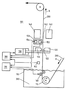
Figure 1 shows the device 100 according to the invention for coating a metal
strip 200
with a liquid coating material 300, for example zinc. For this purpose, the
initially still
uncoated metal strip 200 is conducted in transport direction R in a coating
container
110 filled with the liquid coating material. Within the coating container 110
the metal
strip 200 is deflected with the help of a deflecting roller so that it leaves
the coating
container upwardly. After the transit through the coating container, the still
liquid
coating material adheres to the metal strip 200.
CA 2967713 2018-07-24
,84004200
4b
A roller pair between which the coated metal strip is guided through is
arranged
downstream of the deflecting roller 115 in the transport direction R of the
metal strip
200. The roller pair is
CA 2967713 2018-07-24
CA 02967713 2017-05-12
typically arranged within the coating container 110 so that it is surrounded
by the coating
material 300 during performance of the coating process. One of the rollers is
adjustable as a
correction roller 160 towards the other roller of the roller pair so as to
smooth the metal strip if
an undesired curvature is present. For this purpose, the amount of curvature
of the metal
strip 200 is detected with the help of a curvature sensor 154 and compared
with a
predetermined curvature threshold value. The comparison can be carried out in
a control
device 190. If the amount of curvature of greater than the curvature threshold
value then the
correction roller is adjusted, under the control of the control device 190,
relative to the metal
strip.
Arranged downstream of the roller pair in transport direction R of the metal
strip is a blowing
device 120 which spans a slot 122 through which the metal strip 200 is guided.
Excess
coating material is blown off the surface of the metal strip 200 with the help
of the blowing
device.
In order that blowing onto the upper side and lower side of the metal strip
200 takes place
uniformly it is important that the metal strip 200 runs through the slot 122
of the blowing
device 120 in a predetermined target centre position 128, as symbolised in
Figure 2 in the
form of the solid line in X direction. This target centre position is
distinguished by, in
particular, uniform spacings or spacing distributions from the inner edges of
the slot 122 of the
blowing device 120. Apart from the desired predetermined target centre
position, possible
undesired actual positions of the metal strip are also depicted, as dashed
lines, in Figure 2.
Undesired actual positions for the metal strip are thus present, for example,
if it is twisted
relative to the target centre position or shifted parallelly in Y direction.
With further reference to Figure 1 there can be seen above the blowing device
120 an
electromagnetic stabilising device 140 which in turn has a slot 142 through
which the metal
strip 200 is similarly guided. It is also the case here that the metal strip
200 preferably runs
through the slot 142 in a predetermined target centre position 128, as shown
in Figure 2, so
that in desired manner the forces provided by the electromagnetic stabilising
device 140 can
have a uniform stabilising action on the metal strip 200.
AMENDED SHEET
CA 02967713 2017-05-12
6
A position sensor is provided for detecting a deviation of the actual position
of the metal strip
200 from a predetermined target centre position in the slot 122 of the blowing
device 120. In
addition, a regulating device 180 is provided for regulating the actual
position of the metal strip
200 to the predetermined target centre position in the slot 122 of the blowing
device, as
explained above with reference to Figure 2, by displacing the blowing device
120 with the help
of a displacing device 130. The displacement is carried out in a plane
transverse to the
transport direction R of the metal strip. The regulation is carried out in
response to the
deviation, which is detected by the position sensor 152, of the actual
position from the target
centre position of the metal strip 200. The regulation can optionally also be
carried out with
additional consideration of the amount of curvature of the metal strip
detected by the
curvature sensor 154.
The position sensor 152 and the curvature sensor 154 are both part of a metal
strip detecting
device 150. According to one embodiment, the function of the position sensor
152 and the
curvature sensor 154 can be realised by a single, typically laser-supported,
sensor device,
also termed "laser" for short; the position sensor 152 and the curvature
sensor 154 then form
one constructional unit in the form of the sensor device or the metal strip
detecting device.
According to a first alternative the displacement of the blowing device 120
can be carried out
as a function of the detected deviation of the actual position of the metal
strip from the
predetermined target centre position in the slot 122 of the blowing device. In
other words: if it
is ascertained that the metal strip 200 does not run through the slot 122 in
the target centre
position 128 then the blowing device 120 is displaced with the help of the
displacing device
130 in such a way that the metal strip again runs through the slot 122 of the
blowing device in
the predetermined target centre position 128 so as to ensure the desired
uniform coating.
According to a second alternative or additionally the displacement of the
blowing device 120
can also be carried out with consideration of the adjusted position, which is
detected by a
correction roller detecting device 165, of the correction roller 160 or the
change thereof. For
this purpose, the output of the correction roller detecting device 165 is also
coupled to the
input of the regulating device 180. In this way the displacement of the
blowing device was
improved with respect to a desired maximisation of uniformity during the
coating. The
AMENDED SHEET
CA 02967713 2017-05-12
7
correction roller detection device 165 can be constructed in the form of two
encoders, each of
which is seated on a respective drive of the correction roller 160.
The metal strip and correction roller detection devices 150, 165 are
constructed to preferably
recognise all conceivable deviations of an actual position of the metal strip
from the desired
target centre position. Amongst those is, in particular, a (parallel) shifting
of the metal strip in
X or Y direction or a rotation such as explained above with reference to
Figure 2. Accordingly,
the displacing device 130 - in the case of suitable control by the regulating
device 180 - is
constructed to move the blowing device 120 in a desired manner in a plane
transverse to the
transport direction R of the metal strip, particularly to shift (parallelly)
or to rotate, so as to
realise transit of the metal strip in the target centre position. To that
extent, the illustration of
the displacing device 130 as a piston-cylinder unit is merely exemplifying,
but not limiting.
AMENDED SHEET
CA 02967713 2017-05-12
8
Reference numeral list
100 device
110 coating container
115 deflecting roller
120 blowing device
122 slot of the blowing device
128 target centre position of the metal strip in the blowing device or the
electromagnetic
stabilising device
130 displacing device
140 electromagnetic stabilising device
142 slot of the electromagnetic stabilising device
150 metal strip detecting device
152 position sensor
154 curvature sensor
160 correction roller
165 correction roller detecting device
180 regulating device
190 control device
200 metal strip
300 coating material
= transport direction of the metal strip
X width direction of the metal strip in target centre position
= direction transverse to the plane spanned by the metal strip
= direction perpendicular to the X-Y plane
AMENDED SHEET