Note: Descriptions are shown in the official language in which they were submitted.
CA 02967723 2017-05-12
WO 2016/087557 PCT/EP2015/078441
System and Method for Alternatively Interacting with Elevators
The various embodiments described herein generally relate to electromechanical
or electrical
installations, such as elevator installations, that require interactions with
humans. More particularly,
the various embodiments described herein relate to electromechanical or
electrical installations and a
method for operating electromechanical or electrical installations with
improved man-machine
interaction.
In an electromechanical or electrical installation, a user typically interacts
with the installation via a
man-machine interface (for example, an operating panel with keys or buttons,
or a touchscreen). For
example, in an elevator installation, an elevator user interacts with the
elevator via an operating
terminal, also referred to as a fixture. An operating terminal may be located
inside an elevator car to
place a car call (i.e., to enter a destination floor), another operating
terminal is then located on each
floor to enter a hall call (i.e., to call a car to a floor by pressing an "up"
or "down" button). In contrast,
in installations with a destination control system, the destination floor is
already entered at a floor
terminal before entering an elevator car. Regardless of the kind of control
implemented in an elevator
installation, the interaction between the elevator user and the elevator
occurs typically via
fixtures/operating panels, even when, e.g., an RFID card is used to call an
elevator.
The interactions between a user and the electromechanical or electrical
installation take place in
connection with a dedicated purpose of the electromechanical or electrical
installation. In an elevator
installation, for example, the dedicated purpose is transporting the user from
one floor to another.
Certain installations expand upon the dedicated purpose in that additional
interactions are provided.
For example, US 8,260,042 discloses for an elevator installation an anonymous
passenger indexing
system for security tracking, in which a video processor anonymously monitors
passengers using color
index analysis of each passenger. Based on the monitored position of each
passenger data parameters
such as location, direction, speed and estimated time of arrival are
calculated. An elevator controller
controls elevator dispatch, door operation and security functions based upon
the data parameters.
Further, US 7,298,256 describes a crisis monitoring system that detects a
crisis by identifying a
person's emotion from an utterance of the person. A recording unit records
emotion attribute
information, which includes a feature of a specific emotion in an audio signal
(i.e., in the person's
voice), and a control unit determines a person's emotion by analyzing the
emotion attribute
information. When the determined emotion indicates a crisis situation, an
emergency routine is
executed which includes alerting a control center or a security company.
CA 02967723 2017-05-12
WO 2016/087557 PCT/EP2015/078441
2
An analysis of a vocal input to determine a person's state of mind or mood is
also disclosed in WO
2009/116030 in the context of an access control system. The system inquires a
person at a checkpoint
to determine the person's identity and to decide whether or not access is to
be granted to a person
present at the checkpoint.
In view of these systems, there is a need for a technology that provides for
additional interactions.
Accordingly, on aspect of such an alternative technology involves a method of
operating an electrical
or electromechanical installation. An image signal is received at a computer
from a video camera, and
facial characteristics from a person's face data comprised in the image signal
are determined using the
computer. The facial characteristics are categorized into at least one of
predefined emotion categories
using the computer, and a control signal is generated by the computer
corresponding to the at least one
of predefined emotion categories. The electrical or electromechanical
installation is operated by a
central controller in accordance with one of several operational modes,
wherein the one of several
operational modes is selected as a function of the control signal.
Another aspect involves an electrical or electromechanical installation having
a central processor for
controlling operation of the electrical or electromechanical installation, a
computer communicatively
coupled to the central processor to output a control signal to the central
processor, and a first video
camera communicatively coupled to the computer to output an image signal to
the computer. The
computer includes a memory storing computer instructions to determine facial
characteristics from a
person's face data comprised in the image signal, to categorizing the facial
characteristics into at least
one of predefined emotion categories, and to generate a control signal
corresponding to the at least one
of predefined emotion categories. The central controller operates the
electrical or electromechanical
installation in accordance with one of several operational modes, wherein the
one of several
operational modes is selected as a function of the control signal.
Briefly, the technology described herein provides for an alternative way of
interacting with persons.
That interaction may occur without a person actively participating in the
interaction. The person's
facial expression may therefore be genuine and reflect the person's actual
emotional state.
Determining the emotional state allows adapting the installation's operational
modes to certain
situations. In one embodiment, the person is a passenger in an elevator car of
an elevator installation.
From a psychological perspective, using elevators is for some passengers
challenging because of the
confined space of a car and the closeness to other passengers. If those
passengers and their emotional
states are recognized, it is possible to adjust the operational mode to make
using an elevator more
pleasant. Further, potential risks due to, for example, angry passengers with
an aggressive behavior
can be identified and addressed as early as possible. For example, such a
passenger may receive
CA 02967723 2017-05-12
WO 2016/087557 PCT/EP2015/078441
3
special treatment, e.g., faster service without stops, or may be prohibited
from using the elevator when
found to be a security risk.
The novel features and method steps characteristic of the improved technology
are set out in the
claims below. The improved technology itself, however, as well as other
features and advantages
thereof, are best understood by reference to the detailed description, which
follows, when read in
conjunction with the accompanying drawings, wherein:
Fig. 1 shows a schematic illustration of an elevator installation as
one example of an
electrical or electromechanical installation;
Fig. 2 is a schematic illustration of one embodiment of a computer as
used in the electrical or
electromechanical installation of Fig. 1; and
Fig. 3 is an exemplary flowchart illustrating one embodiment of
operating the electrical or
electromechanical installation.
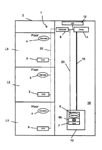
Fig. 1 illustrates one embodiment of an elevator installation 1 as one example
of an electrical or
electromechanical installation. The various embodiments of the improved
technology are described
herein with reference to that elevator installation 1 that allows user
interaction to provide for
transportation between floors Ll, L2, L3 of a building 2. It is, however,
contemplated that the
technology may be applied to other electrical or electromechanical
installations that usually require
user interaction, such as building access systems, public transportation
systems or
security/surveillance monitoring systems.
As used herein, user interaction means any interaction between a user and an
electrical or
electromechanical installation, whether intentional or unintentional,
conscious or unconscious. An
example of an intentional interaction is entering a command at a man- machine
interface, e.g., by
pressing a button, touching a sensor, presenting an information carrier (such
as a badge with a bar
code or an RFID transponder) or uttering a command. In contrast, being
observed by a video camera
in a public place, including an elevator lobby, may be unintentional,
conscious or unconscious. Such
interaction may result in an action (e.g., alarm, change of operation)
performed by the electrical or
electromechanical installation.
In the illustration of Fig. 1, building users and occupants have access and
egress to the various floors
Ll, L2, L3 of the building 2 using the elevator installation 1. Depending on a
particular configuration
of the building 2, the floor L 1 may be a lobby of an office building or a
hotel. In the illustrated
embodiment, the elevator system 1 includes an elevator car 10 and a central
controller 12 (also
referred to as elevator controller 12 (EC)) that acts on a drive 14 to move
the elevator car 10, for
CA 02967723 2017-05-12
WO 2016/087557 PCT/EP2015/078441
4
example suspended by one or more tension members 16, in an elevator shaft 18,
from one of the floors
Ll, L2, L3 to another. A tension member 16 may by a steel rope having a round
cross-section, or a
group of (steel or non-metallic) cords embedded in synthetic material having a
non-round cross-
section, e.g., a rectangular cross-section.
The general physical structure of the elevator installation 1 corresponds to
the physical structure of a
conventional elevator installation. In one embodiment, the physical structure
includes in addition to
the mentioned elements (central controller 12, drive 14 and tension member 16)
a counterweight,
guide rails for the elevator car 10 and the counterweight, safety equipment
such as brakes and safety
circuits for door mechanisms, etc. For illustrative purposes, these elements
are not shown. It is
contemplated that, depending on a particular embodiment of the elevator
installation 1, the
configuration and disposition of these elements in a shaft 18 may vary. For
example, the drive 14 may
be arranged in a separate machine room or directly in the shaft 18 ("machine
room less elevator") at
the top, as shown, or at the bottom of the shaft 18. The operation of such an
elevator installation 1 is
known to the skilled person and, therefore, not described here.
The elevator installation 1 of Fig. 1 includes a system for capturing at least
one parameter of a user. In
one embodiment such a user parameter capturing system is based upon digital
video technology to
generate an image signal corresponding to an individual image or a sequence of
images (frames), i.e.,
a video sequence. For that purpose, a video camera 4 may be used, which can be
operated to generate
individual pictures or a video sequence. The image signal may be processed in
real time. The pictures
or video sequence may be stored on an internal storage medium of the video
camera 4 or transmitted
to an external storage medium.
A video camera 4 may be installed on each floor Ll, L2, L3, as shown in Fig.
1. In another
embodiment, however, some of the floors Ll, L2, L3 may not be equipped with a
video camera 4. In
certain buildings 2 it may suffice to have a video camera 4 only in the lobby,
e.g., on floor L1. An
additional video camera 6 may be positioned within the elevator car 10, as
shown in Fig. 1. In such an
embodiment, an indicator 6b may be positioned inside the elevator car 10 to
inform passengers when
the video camera 6 is recording. The video cameras 4, 6 are communicatively
coupled to a computer 8,
which controls the operation of the video cameras 4, 6 and receives
transmitted video information (i.e.,
image signals) from them. As described below in more detail, the computer 8
processes that video
information and generates in certain situations a control signal for the
elevator controller 12. For that
purpose, the computer 8 is communicatively coupled to the elevator controller
12.
A communicative connection or coupling as used herein is a direct or indirect
connection, which
enables the unidirectional or bidirectional communication between two
entities. Via such a connection
CA 02967723 2017-05-12
WO 2016/087557 PCT/EP2015/078441
or coupling, data signals and/or control signals are transmitted in a manner
known to the skilled
person. The connection or coupling may be achieved by an electrical wiring
system (either as a system
of point-to-point connections or as an electrical bus system, where entities
connected to the bus system
can be addressed), a radio system or a combination of a radio system and an
electrical wiring system.
5 Fig. 1 shows the communicative coupling exemplary through lines 20, 22,
wherein the line 20 extends
between the computer 8 and the elevator car 10, and the line 22 extends
between the computer 8 and
the video camera 4. In one embodiment, the line 22 is a bus system to which
the video cameras 4 are
connected.
The skilled person recognizes that the computer 8 or its functionality of
controlling the video cameras
4, 6 and executing a dedicated software program may be implemented, for
example, in the elevator
controller 12 or in another electrical component of the building 2, e.g., in
an access control system that
controls access to the building 2, floors Ll, L2, L2 and/or rooms of the
building 2. In such a case, the
separately shown computer 8 might be omitted from Fig. 1. Depending on a
particular embodiment,
the implementation of the communicative connection or coupling changes
accordingly. As a matter of
principle, Fig. 1, therefore, is to be viewed as an exemplary embodiment. It
is also contemplated that a
video monitor (not shown) may be present within the building 2 or at a remote
site that displays all or
only selected video recordings (e. g., from the building 2 to allow security
personnel to monitor the
building 2.
Fig. 1 further shows input devices 5, 7 that are communicatively coupled to
the elevator controller 12
and the computer 8. On each floor Ll, L2, L3 an input device 5 is located to
allow a person to interact
with the elevator installation 1, e. g., to call an elevator. The input device
7 is located inside the
elevator car 10 and may be implemented as part of an operating panel that
houses the video camera 6,
the indicator 6b, and the input device 7. A variety of design options exist
for the operating panel; it
may have a glass front behind which the video camera 6, the indicator 6b and
some or all components
of the input device 7 are arranged. If the glass front extends from the car
floor to the car ceiling, the
video camera 6 may be positioned at the upper end of the operating panel so
that the video camera 6
has an optimized view over the interior of the elevator car 10. In that case,
the video camera 6 is
located close to the ceiling to provide for video recordings from an elevated
position. In that case, the
camera's field of view is least obstructed by passengers inside the elevator
car 10. Close to the ceiling,
the video camera 6 may be out of reach so that the risk of vandalism is
reduced. Covering the video
camera 6 or placing it behind the glass front further reduces the risk of
damage. It is contemplated that
the same considerations regarding location and protection apply to the video
cameras 4 installed at the
floors LI, L2, L3.
A CA 02967723 2017-05-12
WO 2016/087557 PCT/EP2015/078441
6
The input device 7 may in one embodiment include a keyboard to allow a
passenger to enter a car call,
i.e., after entering into the elevator car 10 the passenger can enter a
destination floor via the keyboard.
In such an embodiment, the input device 5 on the floor Ll, L2, L3 may have
Up/Down buttons to
allow a waiting passenger to call an elevator. In another embodiment, the
elevator installation 1 may
be equipped with a destination call control system. Such a system allows a
person to enter a
destination floor via the input device 5 already on the floor Ll, L2, L3
before boarding the elevator car
10.
The input device 5 or at the input device 7, or both, may be configured to
read information from an
information carrier carried by a person/passenger. For that purpose, the
respective input device 5, 7 is
equipped with a reader to read data from that information carrier when it is
presented to the reader.
The read data may represent an authorization to operate the input device 5, 7
or a destination call, or
both. In one embodiment, the information carrier has a form factor that
corresponds to a credit card or
an employee badge. Depending on a particular configuration, the information
carrier includes an
embedded memory chip having leads to the surface of the information carrier,
an embedded RFID
transponder in connection with a memory chip, an optical code on the surface
(e.g., a barcode or QR
code), or a combination of these technologies. In the alternative, the
functionality of the information
carrier may be implemented in a portable electronic device (e.g., mobile
phone, smart phone or tablet
PC). These devices may display optical codes, and may also allow radio
communication with other
electronic devices using known technologies such as Bluetooth or NFC (near
field communication). It
is contemplated that the reader is compatible with the technology, or the
several technologies, used by
the information carrier
FIG. 2 shows a block diagram of an exemplary embodiment of a computer 8 (e.g.,
part of an access
control system control unit, part of the elevator controller 12, part of a
reader, part of a database) that
can be used with one or more technologies disclosed herein. The computer 8
comprises one or more
processors 24. The processor 24 is coupled to a memory 26, which comprises one
or more computer-
readable storage media storing software instructions 28 and a database. The
computer-readable storage
media can comprise, for example, one or more of optical disks, volatile memory
components (such as
DRAM or SRAM), or nonvolatile memory components (such as hard drives, Flash
RAM or ROM).
When executed by the processor 24, the software instructions 28 cause the
processor 24 to perform
one or more of the method steps disclosed herein. Further embodiments of the
computer 8 can
comprise one or more additional components. The computer 8 can be connected to
one or more other
computers or electronic devices through an input/output component (interface)
30. In at least some
embodiments, the computer 8 can connect to other computers or electronic
devices through a network.
In particular embodiments, the computer 8 works with one or more other
computers, which may be
CA 02967723 2017-05-12
WO 2016/087557 PCT/EP2015/078441
7
located locally, remotely, or both. One or more of the disclosed methods can
thus be performed using
a distributed computing system.
With the understanding of the structure of the elevator installation 1 and the
functionalities of its
components described in connection with Fig. 1 and Fig. 2, various embodiments
of a method of
operating the elevator installation 1 are described in connection with Fig. 3.
This figure describes an
exemplary flowchart of a method of operating the elevator installation 1.
Referring to Fig. 3, the method starts at a step S1 and ends at a step S7. At
a step S2, an image signal
is received. In one embodiment, the computer 8 receives an image signal from
one of the video
cameras 4 on one of the floors Ll, L2, L3. The image signal represents an
image or a sequence of
video images (e.g., a sequence of video frames). The video cameras 4, 6 may be
in constant operation
regardless of the actual operational status of the elevator installation 1. In
another embodiment a video
camera 4, 6 may be activated when triggered by a specific event. For example,
the video cameras 4, 6
may be activated when movement is detected on a floor L1, L2, L3, or in the
elevator car 10, or upon
demand (e.g., by security personnel).
In a step S3, facial characteristics are determined from a person's face data
comprised in the image
signal. The facial characteristics are derived from a person's facial
expression using the computer
instructions 28 and the database stored in the memory 28 of the computer 8.
Computer-assisted
analysis of facial expressions is described, for example, in Shichuan Du, et
al., "Compound Facial
Expressions of Emotion", published online March 31, 2014 at
www.pnas.org/cgi/doi/10.1073/pnas.1322355111, pages E1454-E1462. That
publication describes a
computer model that allows recognition of 21 different facial expressions of
emotion, including happy,
happily surprised, happily disgusted, surprised, sad, fearful, sadly fearful,
fearful angry, fearful
surprised, angry, sadly angry, hatred, disgusted, appalled, and awed. For that
purpose, the publication
uses a facial action coding system given by a set of action units. Each action
unit codes the
fundamental actions of individual or groups of muscles typically seen while
producing facial
expressions of emotion. As potential applications of that model the
publication mentions the diagnosis
and treatment of psychiatric disorders (e.g., schizophrenia), cognitive
impairments (e.g., autism) and
studies of pain. The computer 8 performs an analysis of a person's facial
expression on basis of that
computer model.
Depending on a particular software configuration, the computer instructions 28
and the database of the
computer 8 may first perform an analysis of the received image signal to
locate the person's face in an
image. Using a computer to locate a face in a video image is described, for
example, in US 8,494,231
B2. In the context of recognizing a face in a video, US 8,494,231 describes
running input on-demand
CA 02967723 2017-05-12
WO 2016/087557 PCT/EP2015/078441
8
video through a processing pipeline having integrated modules that perform
face detection, face
tracking, face grouping and face recognition to generate face galleries. On a
more theoretical level, an
algorithm for detecting the location of a face in an image is described in J.
Huang, et al., "Automatic
Face and Gesture Recognition", pages 248 ¨ 252, Proceedings of the Second
International Conference
on Automated Face and Gesture Recognition 14-16 Oct 1996. Once the face is
located, the person's
facial expression can be analyzed by the computer 8.
In one embodiment, the various facial expressions and associated emotions are
categorized for the
specific application in the elevator installation 1. This is based on the
assumption that certain emotions
may be more or less of a concern for that specific elevator application. For
example, a happy person
may not be of any concern, but an angry person may be a concern when having to
travel with several
passengers in an elevator car 10.
Proceeding to a step 54, the determined facial characteristics are evaluated
to determine if they fit in
one of defined categories of emotion. If the facial characteristics fit, the
method proceeds along the
YES branch to a step S5. In the step S5, the computer 8 generates a control
signal that is associated
with the category into which the facial characteristics fit.
In certain cases the determined facial characteristics may not fit in one of
the defined categories. For
example, this may happen if the image signal does not allow an unambiguous
detection of a face
because the person turned the face away from the video camera 4, 6 or because
of poor illumination of
the scene. To avoid the latter case, the area observed by a video camera 4, 6
is to be sufficiently
illuminated. In such situations, the computer 8 is in one embodiment set to
assign no facial
characteristics to the person; this is viewed herein as a "no fit." In that
case, the method returns along
the NO branch to the step S3.
In one embodiment, the elevator installation 1 may be operated according to
one of several operational
modes. Each operational mode is associated with a particular control signal.
The control signal
generated in the step S5 determines which operational mode is to be selected
so that the operational
mode is selected as a function of the control signal. Proceeding to a step S6,
the central controller 12
operates the electrical or electromechanical installation 1 in accordance with
the selected operational
mode.
For each operational mode of the elevator installation 1, specific settings or
parameters are defined to
address a passenger's state of emotion. Exemplary setting and parameters are
set forth in the following
table (Table 1). It is contemplated, however, that other measures may be
implemented depending on a
particular embodiment (e.g. in a busy office building during peak times,
individual settings such as
CA 02967723 2017-05-12
WO 2016/087557 PCT/EP2015/078441
9
temperature may not be suitable). Further, it is contemplated that other
categories and/or facial
characteristics may be defined.
Category Emotion Measure
1 Neutral Any available car 10 may be assigned to
that
(incl. happy, happily surprised, passenger, no particular performance or
happily disgusted, surprised) environmental considerations
2 Sad, fearful Adjust environmental settings, e.g.,
light, sound,
(incl. sadly fearful, fearful show distracting multimedia clip,
temperature.
angry, fearful surprised) Communications.
3 Angry, hatred Assign an empty car 10 when destination
call is used,
(incl. sadly angry) service that person's call first to
reduce waiting time,
no intermediate stops to bring person to destination
floor quickly. Communications.
4 Disgusted, appalled Adjust car settings, e.g., light,
temperature,
(incl. awed) multimedia clip
Table 1
In the non-limiting example of Table 1, there are four emotion categories
shown. The first category is
defined as neutral and includes emotions like happy, happily surprised,
happily disgusted and
surprised. The first operational mode is selected when the facial
characteristics fit in the first emotion
category. In the first operational mode the central controller 12 operates the
electrical or
electromechanical installation 1 according to predetermined first operational
settings, wherein the first
operational settings correspond to predefined normal operation settings. The
emotions in the first
category are viewed as not requiring particular settings or parameters so that
the installation 1 is
operated according to its normal settings. For example, a passenger showing
emotions of the first
category can be assigned any available car 10 without considering settings or
parameters that affect
the performance (e.g., service time, occupancy) or environment (e.g.,
illumination/light, sound
(music), audio/video (multimedia) or temperature within the elevator car 10).
The second category includes sad and fearful emotions including emotions like
sadly fearful, fearful
angry and fearful surprised. The second operational mode is selected when the
facial characteristics fit
in the second emotion category. In the second operational mode the central
controller 12 operates the
electrical or electromechanical installation 1 according to predetermined
second operational settings
that modify environmental parameters of the electrical or electromechanical
installation 1. For
example, a passenger showing emotions of the second category may require more
attention that one
= CA 02967723 2017-05-12
=
WO 2016/087557
PCT/EP2015/078441
with emotions of the first category to make the elevator trip more pleasant
and enjoyable.
Environmental parameters that may affect the passenger's emotions include the
light, sound (music),
audio/video (multimedia) or temperature within the elevator car 10.
5 The third category includes angry and hatred emotions including emotions
like sadly angry. The third
operational mode is selected when the facial characteristics fit in the third
emotion category. In the
third operational mode the central controller 12 operates the electrical or
electromechanical installation
1 according to predetermined third operational settings that affect the
performance of the electrical or
electromechanical installation 1. For example, an angry or hatred passenger
may show aggressive
10 behavior within a crowded elevator car 10 and affect other passengers.
To avoid such a situation, that
passenger may be better served by assigning an empty car 10 to the passenger.
Alternatively, or in
addition to the previous measure, the angry passenger's call may be handled
first to reduce the
passenger's waiting time. Also, a trip without intermediate stops may be
provided. Considering the
installation 1 as a whole, these measures affect its performance. In some
cases the performance is
reduced because other passengers have to wait longer due to a trip without
intermediate stops.
The fourth category includes disgusted and appalled emotions including
emotions like awed. The
fourth operational mode is selected when the facial characteristics fit in the
fourth emotion category.
In the fourth operational mode the central controller 12 operates the
electrical or electromechanical
installation 1 according to predetermined fourth operational settings that
modify environmental
parameters of the electrical or electromechanical installation 1. The
environmental parameters can be
those described in connection with the second operational mode.
In one non-limiting example, the elevator installation 1 is equipped with a
destination control system
and has several elevator cars 10 available to handle the traffic. In such an
environment, a person
approaches an elevator landing on a floor Ll, L2, L3 where a video camera 4 is
installed. The user
presents an electronic card (an RFID card) to a reader of the input device 5
that is positioned on that
floor L1, L2, L3. The reader reads credential information from the card (in
this case, an identification
number associated with the person and a destination floor) and sends this
information to the elevator
controller 12. The elevator controller 12 uses this information to determine
that the person is
authorized to use the elevator, and to assign an elevator car 10 to service
that person's call.
While the person is at the landing, the computer 8 executes the computer
instructions 28, determines
the person's facial characteristics, assigns them to a category, and selects
the most suitable operational
mode for that category. For example, if the person is angry or seems hatred
(third category), which
may cause stress, the computer 8 generates a control signal that sets the
third operational mode. That
mode is set to optimize the time of an elevator trip between placing a call
and arriving at the
CA 02967723 2017-05-12
WO 2016/087557 PCT/EP2015/078441
11
destination floor. That time may be referred to as "service time" of the
elevator trip. In one
embodiment, that mode requires immediate service with no stops so that the
(angry, stressed) person is
transported to the destination floor as quickly as possible.
In another non-limiting example, the elevator car 10 may stop during a trip
without the doors opening,
e.g., between floors Ll, L2, L3. In such a case, it usually takes some time
until service personnel
arrives on site to solve the problem. Although every person in the elevator
car 10 knows that help is on
its way, a person may not tolerate being stuck in such a confined space,
either alone or with unknown
persons. With the video camera 6 being active, the computer 8 could determine
if a person is losing its
temper, e.g., becomes angry (third category) or fearful (second category). If
this is detected early, the
computer 8 may generate a control signal that sets the most appropriate
operational mode. For
example, regarding the second and third categories and the respective
operational modes, the computer
8 may cause communications with the interior of the car 10, such as providing
an announcement with
instructions and/or information. For example, information may be provided
about when the service
technician will arrive, or, if a multimedia system is available inside the
elevator car 10, the location of
the service technician could be illustrated on a map. Having information like
that may comfort and/or
distract the passenger.
Although some embodiments of the various methods disclosed herein are
described as comprising a
certain number of method acts, further embodiments of a given method can
comprise more or fewer
method acts than are explicitly disclosed herein. In additional embodiments,
method acts are
performed in an order other than as disclosed herein. In some cases, two or
more method acts can be
combined into one method act. In some cases, one method act can be divided
into two or more method
acts.
Having illustrated and described the principles of the disclosed technologies,
it will be apparent to
those skilled in the art that the disclosed embodiments can be modified in
arrangement and detail
without departing from such principles. In view of the many possible
embodiments to which the
principles of the disclosed technologies can be applied, it should be
recognized that the illustrated
embodiments are only examples of the technologies and should not be taken as
limiting the scope of
the invention. Rather, the scope of the invention is defined by the following
claims and their
equivalents. I therefore claim as my invention all that comes within the scope
of these claims