Note: Descriptions are shown in the official language in which they were submitted.
CA 067735 2017--12
WO 2016/075487 PCT/GB2015/053458
- 1 -
DRILLING RIG
The present invention relates to a drilling rig and a
system of operating a drilling rig and particularly, but
not exclusively to a system for mitigating collisions on a
drilling rig, a system for mitigating accidents on a
drilling rig and a system for monitoring the health of
tools on the rig floor.
In the drilling of a wellbore a drill bit is arranged
in a bottom hole assembly on the lower end of a drill
string. The drill bit is rotated to bore a hole in a
formation. The formation may be below water or may be dry
land. An upper end of the drill string passes through an
opening in a drill floor of a drilling rig. The opening is
known as well centre. The drill string is constructed on a
drilling rig and then lowered into the hole using a
wireline drawn-in and let-out by a winch known as a
drawworks. The wireline passes over a crown block fixed to
the top of a derrick, and passes down to a travelling block
which travels up and down within the derrick to raise or
lower joints of drill pipe and/or the entire drill string.
The drill bit is, at least initially, rotated by
rotation of the drill string. The drill string may be
rotated by a rotary table arranged at well centre in the
drill floor. In this case, a swivel is hooked on to the
travelling block, which has an elevator attached thereto
in which the drill string is held for lowering and raising.
Alternatively or additionally, the drill string may be
rotated by a top drive movable up and down a track in a
derrick of the drilling rig. The travelling block is
connected to the top drive to raise and lower the top drive
along the track. A top drive elevator depends from the top
drive on bails. As the hole is drilled, joints of drill
- 2 -
pipe are added to the drill string to allow the drill bit
to drill deeper into the formation. The joints of drill
pipe are usually added in stands of two or more usually
three joints. The stands of drill pipe are made up off well
centre in a mouse hole or powered rat hole. The stands are
made up using an iron roughneck or: a separate spinner to
run threaded pin ends of a upper joint of drill pipe into
corresponding threaded boxes of a lower joint of drill pipe
to make a connection; and a tong to torque the connection.
Pipe handling apparatus moves joints of pipe from a pipe
rack into alignment with the mouse hole or rat hole.
Another pipe handling apparatus moves the stand of dill
pipe directly to well centre for connection to the drill
string or into a rack comprising slots defined by fingers
in an array known as a finger board for buffer storage,
such a rack and pipe handling apparatus are disclosed in
US-32-8550761. The stand of drill pipe is then connected
to the string of drill pipe suspended in the hole. The
connection is made using an iron rough neck or a
separate spinner and tongue.
It is also know from WO 2011/135311 to have a system
for determining the position of a downhole drill pipe
relative to an iron roughneck. The system comprises: an
imaging means arranged to capture an image of the drill
pipe in a region of the pipe for engagement by the device;
and a processor operable to analyse said captured image
and to determine therefrom the position of the drill pipe
relative to the iron roughneck.
The drill string is removed from the well, in a
procedure known as "tripping-out". Typically, the top drive
elevator lifts a stand length of drill pipe out of the
Date Recue/Date Received 2022-01-11
CA 02967735 2017-05-12
WO 2016/075487 PCT/GB2015/053458
- 3-
hole. The spider in the rig floor at well centre prevents
the rest of the drill string from falling downhole. The
stand length of drill pipe is disconnected from the drill
string using an iron roughneck. The stand is "set-back" in
the finger board.
To improve the integrity of the hole, the hole may be
lined with casing. A string of casing is lowered into the
hole and hung from a wellhead or template on the surface
of the formation. During construction of the casing string
a section of casing is added to the casing string as it is
lowered into the hole. The section of casing is moved into
alignment with a pipe handling apparatus or an elevator is
used to lift the upper end from a conveyor so that the
lower end swings into alignment with well centre and the
casing string suspended in the hole. The section of casing
is then connected to the string of casing suspended in the
hole. The connection is made using: a casing iron rough
neck, separate casing spinners and tongues; or using a
casing running tool (CRT) using rotation of the top drive
whilst torque is resisted by the casing string being held
in a spider in the floor of the drilling rig. Once the
string of casing is complete, it is hung from the template
or wellhead. Centralizers may be used to centre the casing
in the hole.
The casing may be cemented in place.
The drill bit and drill string are "tripped-in" to
the well. The drill bit on a BHA and subsequently stands
of drill pipe from the finger boards are moved to well
centre one at a time using the pipe handling arm and
connected in the same procedure as described above, except
for the fact that the hole is pre-drilled and cased, so
the procedure is carried out at a much quicker pace than
CA 02967735 2017-05-12
WO 2016/075487 PCT/GB2015/053458
- 4-
when drilling.
Drilling then continues. When the drill string is
long, it is difficult to transfer torque from the top drive
or rotary table to the drill bit. A mud motor may be used.
The mud motor is installed near to the bottom hole
assembly. The circulation of drilling mud through the mud
motor rotates the drill bit.
More, smaller diameter casings may be installed and
cemented in place as the hole is drilled further.
Furthermore, a liner may be set, which is a casing which
is not tied back to the wellhead, but hung from the lower
end of a previously hung casing.
Lateral holes may be formed from the main hole, using
tools such as window mills and whipstocks. The lateral
holes can extend several kilometres from the main hole.
Specialist tools may be required during the drilling
process, such as a continuous circulation tool, such as
the one shown in WO-98/16716 and WO 2009/093069. These
tools are brought up to the rig floor and placed at well
centre. The continuous circulation tool is then connected
into the drill string between the rig floor and an upper
sub connected to a top drive. These tools allow a
continuous circulation of drilling mud whilst dill pipe is
added or taken away during tripping and thus maintains a
constant pressure in the wellbore.
The hole may then be cleaned using cleaning tools on
the end of a drill string and made ready for receiving oil
from the formation, known as the production phase.
Various operations can be carried out during the
production phase, such as work over and well stimulation
operations to attempt to obtain more oil from the well.
These operations may be carried out using coiled tubing
CA 02967735 2017-05-12
WO 2016/075487 PCT/GB2015/053458
- 5-
and tools connected thereto. These operations may be
carried out from the well head or the rig floor.
Thus several standard operations are carried out
during the construction and production phases over the life
of a well, such as: drilling phase; tripping-out phase;
casing phase; tripping-in phase; completion phase;
production phase; and intervention phase; as well as
specialist operations. Different tools are required for
each phase and thus tools are changed over on the rig floor
between phases.
The inventors have also observed that if a tool used
on a rig floor becomes faulty, the rig operations often
have to cease whilst men retrieve and replace the faulty
tool. Significant down time can occur. This is
particularly, but not exclusively relevant in a dual
derrick system, where operations switch from drilling, to
casing to completion etc. very quickly and frequently, thus
a lot of time is lost as "flat time", whilst changing the
configuration of tools at the well centres.
The inventors have observed that there is a risk of
collision between tools, equipment and other items on a
rig floor of a drilling rig. The inventors have also
observed that drillers and tool pushers overly estimate
the size of items such as tools, pipe and equipment moving
on around a drilling rig in order to avoid collisions.
Furthermore, the speed at which tools, equipment and other
items are moved around a rig floor is often overly reduced
by the drillers and tool pushers to mitigate collisions.
Furthermore, the inventors have observed that rig hands on
the rig floor are in potential danger when in close
proximity to tools in operation and when tools and
equipment are moved around a drilling rig.
CA 02967735 2017-05-12
WO 2016/075487 PCT/GB2015/053458
- 6-
In accordance with the present invention there is
provided a system for operating a drilling rig, the system
comprising a drilling rig having a rig floor, a derrick, a
master control computer system and at least one camera,
the at least one camera capturing a master image of at
least a portion of the rig floor, sending the master image
to the master control computer, the master control computer
system mapping said master image into a model for a zone
management system.
Preferably, the master image is constructed from a
plurality of sub-images, each sub-image captured by a
camera.
Preferably, the master image is analysed by the master
control computer system to obtain three dimensional model.
Advantageously, the master image comprises a grey scale
contrast or colour contrast, preferably the master control
computer system analysis said contrast to produce said
model. Preferably, the camera captures range data, the
range data used to defining points for said model.
Preferably, the model is created in real time.
Advantageously, the master image is captured at least once
every minute and an updated model created in real time.
Preferably, the master image is captured at least once
every second and an updated model created in real time.
Advantageously, the master image is captured at least ten
times every second and an updated model created in real
time. An algorithm can be used to reduce the need for
computing power and increasing speed of processing by
identifying areas of the model which have changed and only
updating the changing parts of the model, for example using
block matching used in MPEG-2.
Advantageously, the model is used in a collision
CA 02967735 2017-05-12
WO 2016/075487 PCT/GB2015/053458
- 7-
mitigation system. Preferably, the model is used in a
system for mitigating accidents on a drilling rig.
Advantageously, the model is used in a health check system.
The present invention also provides a system for
mitigating collisions on a drilling rig, the drilling rig
comprising a rig floor and a derrick, the system comprising
a plurality of cameras, each camera of said plurality of
cameras capturing an image of a zone on a rig floor in real
time and sending the image to a master computer system,
the master computer system processing said image of the
zone and based on the content of said image allow or
disallow an item to move into or within a particular part
of said zone.
Advantageously, at least one of said plurality of
cameras is mounted in the derrick providing a plan view of
the rig floor. Preferably, the camera is arranged on a
track and movable therealong. Advantageously, the camera
is movable on a universal joint, which may be provided with
means such as a grub screw to lock the universal joint in
one position. The camera may be movable by remote control
to select a field of vision.
Advantageously, the master computer system scans said
image for items. Preferably, the analysis comprises the
steps of scanning the image for items, each item having an
item image stored in a memory of the master computer
system. For example, an item image is a top plan view of
an iron roughneck, well centre, a spider, a spider skid, a
dog house skid etc.. Advantageously, the system further
comprises the step of the master computer system plotting
a location for each identified item on said map.
Advantageously, a default unsafe zone is stored in said
master computer system for each of said at least one item
CA 02967735 2017-05-12
WO 2016/075487 PCT/GB2015/053458
- 8-
image. Preferably, an in-use unsafe zone is stored in the
master control system for each of said at least one item
image, advantageously the master control computer system
is provided with realtime data indicating if said item is
operating and preferably particulars of the type of
operation.
Preferably, the system comprises a plurality of item
skids moving on said rig floor. Advantageously, each item
skid comprises information gathering devices, such as at
least of a: location sensor, orientation sensor, ID tag
reader; weight sensor; memory, where preferably
information from the information gathering devices is
collated and processed by said master computer system.
Preferably, the skid further comprises an on-board computer
system for collating data information from said plurality
of information gathering devices.
Advantageously, the skids are arranged on a network
of rails.
Preferably, said image is digital, although may be an
analogue image. Preferably, a high definition analogue
camera is used in combination with a range data collecting
apparatus, which may be light based, such as a time of
light laser, differential path or be sound based, such as
sonar. Advantageously, said image comprises or is wholly
built up from range data, such that a three dimensional
image is captured and sent to the master computer system.
Preferably, the range data is measured for each hundred
square millimetres of the zone.
Advantageously, the camera is a range imaging camera.
Preferably, the camera is a range imaging camera is one of
the following types: time-of-flight, stereo triangulation,
sheet of light triangulation type, structured light type.
CA 02967735 2017-05-12
WO 2016/075487 PCT/GB2015/053458
- 9-
Preferably, the image is captured every one to five
minutes. Advantageously, the image is captured every ten
seconds to sixty seconds. Preferably, the image is captured
every one to ten second. Advantageously, image is captured
between fifty and one times per second.
Most equipment moving around the rig is equipped with
sensors that report position and intended motion to a
master computer control system.
Rig hands on a rig floor are needed to fulfil a number
of tasks, such as moving and operating tools, inspection,
maintenance, problem solving etc.. Rig hands are managed
by the driller or tool pusher, but not to the extent their
position on the drilling rig is always known. Thus their
location at any point in time is not necessarily known by
the driller, tool pusher or master computer control system
running automated operations and tools on the drilling rig.
The rig hands always wear safety helmets on the rig
floor. This is a mandatory safety requirement and rig hands
are used to following this procedure. A location device
and transmitter may be installed in the rig hand's safety
helmet to transmit a signal back to a receiver linked to
the master computer control system. The master computer
control system is provided with an algorithm to assess the
rig hand's location on the rig floor which is continuously
monitored. In this way, potentially dangerous operations
can be delayed or stopped if the rig hand is within an
unsafe zone at the location of and around the potentially
dangerous operation. The inventors have observed that this
system is very useful, but could benefit from a more robust
alternative or additional system.In accordance with
another aspect of the present invention there is provided
a system for mitigating accidents and optionally,
CA 02967735 2017-05-12
WO 2016/075487 PCT/GB2015/053458
- 10-
mitigating down time on a drilling rig, the drilling rig
comprising a rig floor and a derrick, the system comprising
a plurality of cameras, each camera of said plurality of
cameras capturing an image of a zone on a rig floor in real
time and sending the image to a master control computer
system, the master control computer system processing said
image of the zone analysing said image to detect the
presence of a rig hand, the master control system having a
map of unsafe zones about items on the drilling rig and
assessing if the rig hand is within said unsafe zone and
based on said assessment allowing or disallowing an item
to operate in or be conveyed into said unsafe zone.
A rig hand has a number of identifiable signatures
which do not vary considerably from one rig hand to
another, but do vary considerably from other objects found
on a rig floor. Such a feature is the helmet. Another
feature is the face of the rig hand. Another is the rig
hands heat signature.
Preferably, the map of unsafe zones is obtained by
analysing an image obtained from a camera, which may be
different or the same cameras. Advantageously, the analysis
comprises the steps of scanning the image for items which
stored in a memory. Preferably, the scanning comprises
holding at least one item image and scanning said image
for said at least one item image, and advantageously
plotting a location for each identified item on said map.
Advantageously, a default unsafe zone is stored in said
master control computer system for each of said at least
one item image. Preferably, an in-use unsafe zone is stored
in the master control system for each of said at least
one item image, advantageously the master control computer
system is provided with realtime data indicating if said
CA 02967735 2017-05-12
WO 2016/075487 PCT/GB2015/053458
- 11-
item is operating and preferably particulars of the type
of operation.
Optionally, the camera is a heat sensing camera for
optionally identifying inanimate objects and optionally
identifying rig hands. The master computer control system
may comprise an algorithm for filtering out parts of the
obtained images which are not likely to be rig hands. For
example, the structure of the drilling rig has a heat
signature which is very different to that of a rig hand
and thus the master computer control system filters out
large parts or all of the image. Certain movable machines,
such as an iron roughneck, has a heat signature which is
very different to that of a rig hand and thus the master
computer control system filters out large parts or all of
the image. Furthermore, certain known items are static and
always present of a rig floor, such as a derrick, towers,
racks, drawworks, dog house etc.. Details of these known
items may be contained in a known items database. The
computer system may be provided with an additional
algorithm to filter out parts of the image of those details
held in the known items database. The parts of the image
that are left are then analysed using further algorithms.
The system thus comprises or further comprises a heat
sensing camera such as a thermal imaging camera. The master
computer control system may further comprise a database of
known heat signature profiles for machines or any other
object likely to be found on a rig floor. The master control
computer system may be provided with an algorithm to
compare the obtained heat signature profiles with those in
the database to discount them from being a rig hand.
Rig hands generally have an identifiable heat pattern
signature. The master computer control system is optionally
CA 02967735 2017-05-12
WO 2016/075487 PCT/GB2015/053458
- 12-
provided with an algorithm to assess if there is a heat
pattern which is indicative of a rig hand. The master
computer control system is also provided with an algorithm
to assess the location of the heat pattern indicative of a
rig hand on the rig floor. Optionally, the thermal imaging
capers is provided with a range imaging device, which
facilitates obtaining a location co-ordinate on the rig
floor.
A, rig hand has certain identifiable visible signatures
which do not vary considerably from one rig hand to
another. Such a rig hand feature is a helmet, face or
facial features. It is thus preferable for the system to
have a camera for receiving reflected visible light
information to assess a visible signature of at least part
.. of the rig hand. Optionally, the system also comprises a
heat sensing camera for detecting a heat signature of a
rig hand and/or to discount items in the field of view of
the camera of items not matching the heat signature of the
rig hand. Such items are inanimate objects, such as
structure in the rig floor area and operating machines. If
the two results (light and heat sensing) are positive, it
is highly likely that the system has identified a rig hand.
If only one of the two cameras (light and heat sensing)
identifies a rig hand, the system assumes there is indeed
.. a rig hand in that location. In this way, the system has
more redundancy and less likely to allow an operation
within an unsafe zone to be carried out.
For example, a rig hand may be wearing a fire
resistant suit which may be highly insulated and thus not
allow a rig hand's heat signature to be detected by the
heat sensing camera. However, the light sensing camera will
detect the rig hand from his outline profile signature or
CA 02967735 2017-05-12
WO 2016/075487 PCT/GB2015/053458
- 13-
part of the outline, for example, the outline of his
helmet. Furthermore, in inclement weather conditions, such
as thick fog or heavy rain, the light sensing camera may
not be able to identify the outline profile of the rig
hand, but will be able to identify the rig hand's heat
signature.
The master computer control system may be provided
with an algorithm to keep a tally of rig hands on the rig
floor. Optionally, the master computer control system also
comprises an algorithm to compare the tally with the number
of rig hands located using the system of the invention on
the rig floor. If the numbers are not equal, a further rig
hand signature is looked for or the tool pusher or driller
is alerted. The master computer control system may also be
provided with the number of the helmet location devices
active on the rig floor as a further check.
Analysing images in series and keeping a continuous
update of rig hand's location will also add robustness to
the preferred solution. Most drilling rigs have specific
walking rails or platforms to enter and exist working
areas. Start tracking on this defined corridors or gates
would remove uncertainty on the topic of person vs machine.
A system that passes people information position from one
image frame to the other will propagate location from areas
of high certainty to those of higher uncertainty.
Information from the rig hand tracking system can then
be combined with that of all the machine positions for a
complete anti-collision system. Therefore, mitigating
accidents and reducing downtime.
Optionally, the camera may also captures wavelengths
in the infrared range. Infrared reflectors may be worn by
the rig hands for producing reflected light for the camera
CA 02967735 2017-05-12
WO 2016/075487 PCT/GB2015/053458
- 14-
to detect and produce an image thereof.
In accordance with another aspect of the invention,
there is provided a system for mitigating accidents on a
drilling rig, the drilling rig comprising a rig floor and
a derrick and a plurality of entrances to the rig floor
the system comprising at least one camera at each of the
plurality of entrances, each camera capturing an image of
a rig hand or item passing through the respective entrance
in real time and sending the image to a master control
computer system, the master control computer system
processing said image of the rig hand or object executing
an algorithm to assess if said image comprises the presence
of a rig hand, the master control system maintaining a
tally of rig hands on the rig floor. Optionally, a further
camera may be required for assessing when a rig hand exits
the entrance to the rig floor.
In accordance with another aspect of the present
invention there is provided a system for monitoring the
health of a tool on a drilling rig the system comprising
a camera positioned to monitor said tool and a health check
computer control system having at least one reference image
stored therein, the camera sending a real time image of
said tool to said health check computer control system,
said master computer control system comparing said real
time image with said at least one reference image, noting
differences, and sending a signal to a health check
computer if the difference is likely to affect the health
of the tool.
Advantageously, the health check computer sends a
signal to the tool to cease operation. Preferably, the
health check computer sends a signal to a group of tools
including the tool to cease operation. Advantageously, the
CA 02967735 2017-05-12
WO 2016/075487 PCT/GB2015/053458
- 15-
health check computer sends a signal to an interface, such
as a visual display, to alert the driller or tool pusher
or operator of the tool if a difference is noted which is
likely to affect the health of the tool.
Advantageously, the health check computer is loaded
with algorithms to difference is likely to affect the
health of the tool. Preferably, the algorithms comprise a
colour differentiation algorithm. Advantageously, the
health check camera includes a range measuring apparatus,
the system comprising measuring and recording range data
in said reference image, the algorithms comprising a range
comparison algorithm for assessing differences in range.
Advantageously, the range data comprises relative ranges,
such as the depth of a crack which was not apparent in the
reference image.
Preferably, the tool is one of an: elevator; top drive
system, iron roughneck; crown block; travelling block;
cranes; pipe tail handlers; equipment skids; tool skids;
dog house skids.
Range imaging cameras are used to create a three
dimensional representation of the rig floor. A number of
cameras are installed around the rig floor.
The range imaging cameras may be a stereo
triangulation type in which two spaced cameras are pointed
to the same spot on the rig for determining the depth to
points in the scene.
The range imaging camera may be a sheet of light
triangulation type wherein the zone is illuminated with a
sheet of light which creates a reflected line as seen from
the light source. From any point out of the plane of the
sheet the line will typically appear as a curve, the exact
shape of which depends both on the distance between the
CA 02967735 2017-05-12
WO 2016/075487 PCT/GB2015/053458
- 16-
observer and the light source, and the distance between
the light source and the reflected points. By observing
the reflected sheet of light using a high resolution camera
and knowing the positions and orientations of both camera
and light source, it is possible to determine the distances
between the reflected points and the light source or
camera. By moving either the light source (and normally
also the camera) or the scene in front of the camera, a
sequence of depth profiles of the scene can be generated.
.. These can be represented as a 2D range image.
The range imaging camera may be a structured light
type, wherein the zone is flooded with a specially designed
light pattern, structured light, depth can be determined
using only a single image of the reflected light. The
structured light can be in the form of horizontal and
vertical lines, points or checker board patterns.
The range imaging camera may be a time-of-flight
technique, wherein a light pulse is used to, preferably
with the entire zone captured with a single light pulse,
although point-by-point rotating laser beam is an option.
Time-of-flight cameras capture the whole zone in three
dimensions with a dedicated image sensor, and therefore
have no need for moving parts. A time-of-flight laser radar
with a fast gating intensified CCD camera may achieves
millimetre depth resolution. With this technique a short
laser pulse illuminates the zone, and the intensified CCD
camera opens its high speed shutter only for a few hundred
picoseconds. The 3D information is calculated from a 2D
image series that was gathered with increasing delay
between the laser pulse and the shutter opening.
Preferably, the rig floor is located in a drilling
rig. Advantageously, the rig floor is locate in one of: a
CA 02967735 2017-05-12
WO 2016/075487 PCT/GB2015/053458
- 17 -
drill ship; FPSO; SWATH; tensioned leg platform; and land
rig.
The present invention also provides a system
comprising at least one range imaging camera arranged in a
rig structure of a drilling rig and a master control
computer system, the at least one range imaging camera
capturing images and ranges of a rig floor said images and
ranges uploaded to a master computer control system.
CA 02967735 2017-05-12
WO 2016/075487 PCT/GB2015/053458
- 18-
For a better understanding of the present invention,
reference will now be made, by way of example, to the
accompanying drawings, in which:
Figure 1 is a perspective view of part of a drill ship
having a rig floor in accordance with the present invention
showing inter alia a network of rails and plurality of
skids, the view as seen from a camera forming part of the
invention;
Figure 2 is a schematic top plan view of part of the
drill ship shown in Figure 1;
Figure 3 is a side view of a spider skid for use on
the network of rails;
Figure 4 is a top view of the spider skid shown in
Figure 3 with a spider thereon;
Figure 5 is a side view of the spider skid shown in
Figure 3 with a spider thereon;
Figure 5A is a side schematic view of part of the
spider skid shown in Figure 5, approaching a parking spot
on a rig floor of the drill ship shown in Figure 1;
Figure 58 is a side schematic view of part of the
spider skid shown in Figure 5, at a parking spot on a rig
floor of the drill ship shown in Figure 1;
Figure 5C is a flow diagram showing data flowing into
an on-board data gathering computer and collating an
information package;
Figure 6 is a top view of the spider skid as shown in
Figure 4 and a crane skid on adjacent tracks of the network
of rails as shown in Figure 1 at well-centre;
Figure 6A is a top plan view of the crane skid shown
in Figure 6 on a track with a stationary unsafe zone marked
in dashed and an additional unsafe zone marked in dash dot
line;
CA 02967735 2017-05-12
WO 2016/075487 PCT/GB2015/053458
- 19 -
Figure 7 is a side view of the crane skid shown in
Figure 6 in a stowed position for transportation along the
network of rails shown in Figure 1;
Figure 8 is a side view of the crane skid shown in
Figure 6 with a jib in an extended position in use whilst
on the track of network of rails;
Figure 9 is a flow diagram showing data flow for a
collision mitigation system;
Figure 10 is a flow diagram showing data flow for a
further collision mitigation system;
Figure 11 is a flow diagram showing data flow for a
system for mitigating accidents between rig hands and tools
carried on or forming part of skids;
Figure 12 is a side view of a diverter skid for use
.. on the network of rails shown in Figure 1 the diverter skid
having a diverter thereon and a lifting apparatus for
lifting the diverter on to and from the diverter skid;
Figure 13 is a top view of the diverted skid shown in
Figure 12;
Figure 14 is a side view of part of a land drilling
rig in accordance with the present invention having a rig
floor, the drilling rig in a first stage of operation;
Figure 15 is a side view of the drilling rig shown in
Figure 14 in a second stage of operation;
Figure 16 is a top plan view of the rig floor and cat
walk of the drilling rig shown in Figure 14;
Figure 17 is a view of the rig floor shown in Figure
14 in a third stage of operation from the view point of a
camera forming part of a system in accordance with the
present invention;
Figure 17A is a flow diagram for a system for
mitigating accidents on a rig floor;
CA 02967735 2017-05-12
WO 2016/075487 PCT/GB2015/053458
- 20 -
Figure 17B is a side view of a drilling rig, like the
drilling rig shown in Figure 15 incorporating rig hand
safety apparatus;
Figure 17C is a schematic view of one of the rig hand
safety apparatus shown in Figure 17B;
Figure 17D shows a part of a rig floor area provided
with a further embodiment of a rig hand safety apparatus
of the present invention;
Figure 17E shows a plan view of a rig floor provided
with a multiplicity of rig hand safety apparatus of the
type shown in Figure 17D;Figure 18 is a perspective view
of a top drive system of the present invention on a track
forming part of the derrick shown in Figure 14, the top
drive system comprising an elevator system in accordance
with the present invention;
Figure 19 is a side view of the top drive system shown
in Figure 18;
Figure 20 is a perspective view of the elevator system
as shown in Figure 18;
Figure 21 is a perspective view of an iron roughneck
system in accordance with the present invention, having an
iron roughneck at well centre with an iron roughneck
handling arm in a retracted position;
Figure 22 is a perspective view of the iron roughneck
system shown in Figure 21 with the iron roughneck handling
arm in an extended position;
Figure 23 is a flow diagram showing steps in a method
of checking the health of a piece of equipment on a drilling
rig.
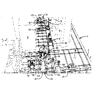
Referring to Figures 1 and 2, there is shown part of
a drill ship, generally identified by reference numeral 1
having a rig floor 2 in accordance with the present
CA 02967735 2017-05-12
WO 2016/075487 PCT/GB2015/053458
- 21-
invention. The perspective view of Figure 1 is as seen from
a camera 26 on a rig structure in an aft of the drill ship
1 of amidships looking towards the bow 3. The drill ship
1 has two derricks 4 and 5 arranged on a starboard side of
the drill ship 1, each with a corresponding well centre 6
and 7 located substantially along a centreline 8 of the
drill ship 1. The top plan view of Figure 2 is as seen from
a camera 28 looking down from a high point on the derrick
mast 4 and 5. The camera 28 may comprise several cameras,
the images obtained from which are combined to form a
composite image. This may be beneficial to obtain a view
of the rig floor 2 without obstruction from structures
rising therefrom. A pipe handling and make-up structure 9
is arranged on a port side of the drill ship 1. The rig
.. floor 2 is arranged between and about the two derricks 4
and 5. The rig floor 2 surrounds the two derricks 4 and 5.
A network of rails 10 is arranged in the rig floor 2. The
network of rails 10 comprise a plurality of straight tracks
11 to 19. Each of tracks 11 to 19 comprises a plurality of
pairs of rails, such as pairs of rails 20, 21.
A plurality of specific item skids are shown in
Figures 1 and 2 on the network of rails 10. A pipe tail
handler skid 30, a dog house skid 31, a riser handling arm
skid 32, a rotary table skid 33, a coiled tubing skid 34
.. and a well intervention coiled tubing injector skid 35.
The network of rails 10 comprises track 11 to 19 in a
layout which will be suitable for a rig floor on a drill
ship 1. All tracks 11 to 19 may be used to route particular
skids between destinations. However, each track 11 to 19
has a main use. The tracks each have a pair of parallel
rails spaced approximately 3.2m.
Tracks 11 and 12 lead around the back of the derricks
CA 02967735 2017-05-12
WO 2016/075487 PCT/GB2015/053458
- 22 -
4 and 5 and past a downhole tool storage area 22 are used
to move particular skids from a bow storage area 23 of the
drill ship 1 to the main rig floor 2.
Track 13 is used mainly as a storage area 40 for item
skids which may be used in an upcoming operation.
Track 14 is used mainly as an access route to guide
skids from the storage area 40 to or close to well-centres
6 and 7. Track 14 also leads to a Christmas Tree elevator
44 located on the port side of the rig floor 2. Christmas
Trees (not shown) are located in an area below the rig
floor 2 on a Christmas Tree skid (not shown).
Track 15 is used mainly as an access route to guide
skids from the bow storage area 23 to or close to the well-
centres 6 and 7. Tracks 14 and 15 are also used for locating
a dog house skid 31, which provide the driller and tool
pusher good views of the well-centres 6 and 7.
Track 16 is used mainly as an access route to guide
skids from the storage area 40 and the bow storage area 23
to and over the well centres 6 and 7. Well centres 6 and
7 are located within a pair of rails 24 and 25 which make
up Track 16. Such item skids which will be required at
well-centre comprise: spider skid 37, diverter skid 38,
BOP test stump skid (not shown), a Continuous Circulation
System skid (not shown) and a rotary table skid 33.
Track 17 is used mainly as an access route to get
specific item skids close to the well-centres 6 and 7,
wherein the specific item skids will generally remain on
the skids on Track 17 while the item is operated, such as:
a pipe tail handler skid 30; an iron roughneck skid (not
shown); a casing tong skid (not shown); a crane skid 36.
Track 18 and 19 are used to route the item skids to
a skid elevator 41. The skid elevator 41 lifts and lowers
CA 02967735 2017-05-12
WO 2016/075487 PCT/GB2015/053458
- 23 -
item skids between the rig floor 2 and a workshop floor
(not shown). Items and item skids to be repaired and
maintained will be moved along the tracks 18 and 19 to the
skid elevator 41 and lowered to the workshop level which
has its own network of rails 43 to move the item skids to
an area of the workshop floor 42 suitable for repairing
and maintaining that particular item skid.
Cameras 26, 26a, 28, 28a, 29, 34' and 34a are placed
in rig structures at a height suitable to obtain a view of
the network of rails 10. Camera 28 is arranged between
derricks 4 and 5 at a height of preferably five to sixty
metres, advantageously, ten to thirty metres above rig
floor towards the top of the derrick height.
A spider skid 37 for moving a spider is shown in
Figures 3 to 5B. The spider skid 37 has: a base 45 for
supporting a spider 67; rail engaging shoes 46; a self-
propelling propulsion system 50; a parking system 55;
automatic hook-up system 60 for power and communication;
and automatic on-board control system 70.
Each of the skids 30 to 38 and any other skid disclosed
herein preferably has a base for supporting an item; rail
engaging shoes; a self-propelling propulsion system; a
parking system; automatic hook-up system for power and
communication; an electronic data gathering system; and
automatic control system.
In use, the spider skid 37 is provided with a flow of
hydraulic fluid to the propulsion system 50 controlled by
the on-board control system 70 to propel the skid. The
propulsion system 50 can operate in a pull or push mode
and in a first direction or a perpendicular second
direction. The propulsion system 50 has a rail gripping
foot 51 and a cycling leg 52. The on-board control system
CA 02967735 2017-05-12
WO 2016/075487 PCT/GB2015/053458
- 24 -
70 controls a flow of hydraulic fluid to selectively
actuate the rail gripping foot 51 and the cycling leg 52
to push or pull the skid along the rail. The spider skid
37 can travel at a speed of between 0.3 and 3 m/min or
faster.
The spider skid 37 has a parking system 55. When the
spider skid 37 is close to a predetermined parking spot, a
locating pin 56 of a locating pin mechanism 57 on an
underside of the square base plate 66 is activated by
master control system 100, which lowers the locating pin
56 on a pin ram 58, as shown in Figure 5A and 5B. The
locating pin 56 is now resiliently biased downwardly
against the rig floor 2 by a resilient means, such as a
spring 59. The spider skid 37 continues under its self-
propulsion until the locating pin 56 passes over a locating
hole 2' at which point the spring 59 biases the locating
pin 56 into the locating hole 2'. The control system 70
ceases the flow of hydraulic fluid to the propulsion system
55, which stops the spider skid 37 from further movement.
The rail gripping foot 51 is actuated to grip the rail 10
to act as a hand brake. Alternatively or additionally, the
parking system 50 may also act as a hand brake to inhibit
the spider skid 37 from moving.
The master control computer system may be located on
the drilling ship 1 and preferably on a dog house skid 31.
Alternatively or additionally, the master control computer
system 100 is located in a control room (not shown) at a
distance from the drilling ship 1, such as on land.
The automatic hook-up system 60 has a combined
hydraulic fluid supply hose and communication lines 61
provided between the rig floor 2 and the spider skid 37.
Combined hydraulic hook-up and communication line hook-up
CA 02967735 2017-05-12
WO 2016/075487 PCT/GB2015/053458
- 25 -
points 62 (only four of many are shown in Figure 2) are
provided in the rig floor 2 between the rails and
approximately 2.8 metres behind each locating hole 2'.
Combined hydraulic hook-up and communication line hook-up
points 62 is connected to a pressurised hydraulic fluid
supply (not shown). A pressurised hydraulic supply is a
common feature of all drilling rigs and drill ships. A
hook-up connector mechanism 60 has connector block 64
comprising a hydraulic connector and a communication line
connector which is arranged beneath a small self-powered
ram 63 to plug the connector block 64 into the combined
hydraulic hook-up and communication line hook-up points 62
The combined hydraulic fluid supply hose and communication
lines 61 are fixedly connected to a top of the connector
block 64 and wound around a self-powered reel 65 which has
a rewind mechanism (not shown).
Before the spider 67 is needed, a command is sent to
operatives in the workshop to prepare the spider skid 37.
The spider 67 is placed on the spider skid 37 in the
workshop and travels up on the skid elevator 41, along
tracks 13 and parked in the buffer storage area 40.
Referring to Figures 5A and 5B, an information package
is collated by the on-board information gathering computer
70. A parking RFID tag reader 71 arranged on the underside
of base plate 45 adjacent the parking mechanism 55. The
RFID tag reader 71 is activated by the on-board information
gathering computer 70 to read parking spot information from
RFID tag 72 in the rig floor 2. The RFID tag 72 reader
sends a parking spot information package, such as location
and a reference number to the on-board information
gathering computer 70. A spider RFID tag reader 75 is
activated by the on-board information gathering computer
CA 02967735 2017-05-12
WO 2016/075487 PCT/GB2015/053458
- 26 -
70 to read spider information from RFID tag 76. If there
is no RFID tag 76 to read, then an on-board information
package is sent to the on-board information gathering
computer 70 indicating that no spider 67 is aboard the
spider skid 37. A further weight sensor arranged on the
base plate 45 and linked to the on-board information
gathering computer 70 may be used to check this is the
case. If the RFID tag reader 70 is able to read the RFID
tag 76, the information relating to the spider 67 is sent
.. to the on-board information gathering computer 70 as a
spider information package. Such spider information
package may include data about the external dimensions,
type of pipe it is suitable for use with, size, and any
faults it may have or have had and subsequent
.. rectifications. An orientation information package such as
orientation of the skid may also be obtained by the on-
board information gathering computer 70 from an orientation
sensor (not shown). A storage memory, such as RAM or EPROM
(not shown) is also arranged on the spider skid 37
containing a spider skid information package, which
contains information such as a reference number and a
description stating that it is a spider skid. The spider
skid information package, orientation information package,
spider information package, on-board information package,
and parking spot information are collated into a skid
information package by the on-board information gathering
computer 70 and sent to the master control computer system
100.
The master control system 100 is provided with a pre-
programmed arrangement for setting a spider at well centre.
The master control system 100 also has skid information
packages from every skid on the network of rails 10.
CA 02967735 2017-05-12
WO 2016/075487 PCT/GB2015/053458
- 27 -
Referring to Figures 1 and 2, the camera 26a captures
a top plan view parking image of the crane skid 36 and any
other item skid in the parking area 40. The parking image
is sent to the master computer control system 100. A
parking sub-image of the crane skid 36 is identified and
analysed. The parking sub-image contains a top plan view
of the crane skid 36. A reference crane skid plan viewin
a stowed position , such as the view shown in figure 6A,
is stored on the master computer control system 100. The
top plan view of the crane skid of the parking sub image
is compared to the reference crane skid plan view. If the
top plan view of the crane skid of the parking sub-image
is significantly different to the reference crane skid plan
view, the master computer control system 100 sends a signal
to the crane skid 37 disallowing movement along the network
of rails 10. A further signal is sent to an operative in
accordance with a health check system, as set out below.
If the top plan view of the crane skid of the parking sub-
image is substantially the same as the reference crane skid
plan view, the master computer control system 100 sends a
signal to the crane skid 37 allowing movement along the
network of rails 10 to its destination at parking spot on
track 17. Thus the above described steps check the health
of the crane skid to enable travel along the network of
rails 10.
In order to assess if the top plan view of the crane
skid 37 of the parking sub-image is substantially the same
as or significantly different from the reference crane skid
plan view, the master computer control system 100 analyses
certain features: a colour contrast about an outline of
the skid against the rig floor; a colour contrast about
features on the base plate of the skid and the item thereon;
CA 02967735 2017-05-12
WO 2016/075487 PCT/GB2015/053458
- 28 -
depth measurement using a range imaging camera to identify
a feature such as a jib to assess if the jib is up or down,
by measuring the difference between a depth measurement to
the skid base or rig floor and a depth to the end of the
jib, taken from a camera high up in a rig structure above
the crane skid. The depth measurement for the jib 81 in
the lowered and raised positions are preprogrammed into a
memory storage area of the the master computer control
system 100.
Preferably, the skids are of a contrasting colour to
the rig floor. Advantageously, the rig floor 2 is of a
predetermined colour and is consistent thereacross.
The master control system 100 automatically sends the
spider skid 37 to its destination when required. For
instance, the driller presses an "install drill pipe spider
in first well centre" button on a visual touch screen
interface 100' of the master control system 100 from the
dog house skid 31. The destination will be on track 16 at
one of the well-centres 6 or 7, in this case well-centre
6. The master control computer system 100 controls the
spider skid 37 to withdraw locating pin 56 from locating
hole 2' and then activate the on-board control system 70
to control the propulsion system 50, so that the spider
skid 37 can move to its destination. From the storage area
40, the spider skid 37 propels itself to track 16 to a
predetermined parking spot 16' next to well centre 6.
Simultaneously, the crane skid 36 (shown in Figures 6 to
8) is sent from buffer storage area 40 to a predetermined
parking spot 17' on track 17 close to well centre 6. The
crane skid 36 has the same self-propelling system, parking
system, automatic hook-up system and automatic control
system as described with reference to the spider skid 37.
CA 02967735 2017-05-12
WO 2016/075487 PCT/GB2015/053458
- 29 -
It should be noted that the reel of the automatic hook-up
system is not shown in Figures 6 to 8 for clarity. The
crane skid 36 has a crane 80 with a jib 81 in a retracted
position and a travelling block 82 in a retracted and
stowed position for transport along the network of rails
10. The crane skid 36 is parked on track 17 at the
predetermined parking spot 17' using a parking mechanism
(not shown), which is identical to the parking mechanism
55 shown and described with reference to the spider skid
37. The crane 80 on crane skid 36 is then operated from a
remote location, such as from the dog house skid 31, using
fly-by-wire control system (not shown) to activate
hydraulic valves in the crane 80, or can be operated in
automatic mode by the master control computer system 100.
The computer system 100 knows the absolute location of the
crane skid 36 and the spider skid 37 from the crane
information package sent from the crane skid's on-board
control system. In automatic mode, the jib 81 is raised
using ram 83 and extended using ram 84 over the spider 67
in the spider skid 37. A hook 85 is lowered on line 86 over
the spider 67 and under a hook receiver of the spider (not
shown). The hook 85 is raised on line 86, lifting spider
67. The crane 80 is rotated on rotating table 87 and lowered
into well-centre 6. The crane 80 thus has an unsafe zone
99 about the crane skid 36 in which it is not safe for rig
hands to be during use. This unsafe zone 99 may be the
expected area of use defined by an angle defined by the
jib 81 over the spider 67 traversing to the well-centre
plus an additional angle in which the jib is likely to move
during this operation and the expected length of extension
of the jib 81, as well as topple zone in case outriggers
are not activated properly or if the item to be lifted is
CA 02967735 2017-05-12
WO 2016/075487 PCT/GB2015/053458
- 30 -
too heavy for the crane. An unsafe zone further includes
an angle in a vertical plane defined by the rig floor 2
and the jib 81 when lifted on ram 83 to an expected working
angle. Thus the unsafe zone may be two dimensional and
preferably three dimensional.
Alternatively, the unsafe zone may be defined by the
entire 360 degrees on movement in which the crane 80 can
traverse in top plan view, maximum length of the jib 81
when fully extended and an angle formed by the jib and the
rig floor when ram 83 is fully extended and a further
safety margin for hook swing on line 86. However, this may
be an unnecessarily large unsafe zone.
The crane skid 36 has an expected stowed plan view as
shown in Figure 6 for transportation along network of rails
10 having an unsafe zone 88 marked in dashed lines.
The crane skid 36 also has an expected unsafe zone
89' when moving along track 17, shown as a northerly
direction. The additional area is an area located in the
direction of travel of the crane skid 36 and is of
sufficient length from the crane skid 36 to allow the skid
to be stopped from the maximum speed of the skid as well
as time for the obstruction to be observed and acted on.
During the spider skid's journey from the storage area
40 to the parking spot 16' on track 16 the skids on the
network of rails 10 are monitored using the cameras 26 and
28. The cameras 26 and 28 capture a series of master images
in real time, preferably at a frame rate of once per second
and each master image is sent to the master computer
control system 100 for analysis. The master images are used
in four ways: to continuously monitor the health of the
skid; to mitigate collisions; to mitigate accidents between
skids and rig hands; and to mitigate accidents between
CA 02967735 2017-05-12
WO 2016/075487 PCT/GB2015/053458
- 31-
tools and rig hands.
The continuous monitoring of the health of the skid
is carried out in the same way as the health of the skid
was assessed in the storage area, and as shown in and
described herein with reference to Figure 23.
The mitigation of collisions is carried out using the
master computer control system 100 using steps shown in
Figures 9 and 10. Referring to Figure 9, the master
computer control system 100 already has information from
the skids 30 to 38 in the form of item skid information
data packages which are continuously updated, preferably
at a rate of at least one update per minute and preferably
one to fifty updates per second. The master computer
control system 100 controls the item skids 30 to 38 by
issuing commands to each item skid according to
predetermined and preprogrammed set of sequences to
complete a particular task, such as an "install drill pipe
spider in first well centre" task as set out above with
reference to Figure 6. If the preprogrammed set of
sequences is followed, a collision should not occur. A
datum location for each item skid 30 to 38 for those which
are travelling along the tracks is estimated by knowing
the departure time from a parking spot, the route and the
speed at which the item skid is travelling e.g. 1 metre
per minute. Location and orientation information for each
item skid is compiled as datum location and orientation
information and/or mapped by the master computer control
system 100 to create a datum map. The items on the item
skids 30 to 38 are in a stowed position and a stowed unsafe
zone is predefined for each item skid.
The series of master images captured in real time are
used to check that the skids 30 to 38 are all in their
CA 02967735 2017-05-12
WO 2016/075487 PCT/GB2015/053458
- 32 -
correct parking spots or travelling on their correct routes
at an expected point therealong as identified by the skid
information data packets and the preprogrammed set of
sequences. The master control computer system 100 creates
sub-images for each skid 30 to 38 to identify each skid.
Once a sub-image has been created, the item skid is
identified using the technique described with respect to
the hierarchical structure as set out above, using colour
contrast data about an outline of the item skid and/or item
on the skid and/or range data for mapping the entire shape
of the item skid and comparing results with a preloaded
reference list of item skids.
Once each item skid has been identified, it is located
using range information from the camera in combination with
directional information and compared to the datum location
and orientation information and preprogrammed set of
sequences. Alternatively or additionally the master image
is compared to the datum map to assess if the item skids
are out of place.
If the item skids 30 to 38 are all in the anticipated
positions, sequence "A" is carried out by the master
computer control system 100, which simply allows the task
to continue.
If one or more of the item skids 30 to 38 is out of
place compared to the datum location and orientation and
preprogrammed set of sequences, a sequence "B" is followed
which comprises an alert sent to the driller or tool pusher
in the dog house 31 and/or an operative according to a set
of health check and hierarchical rules as set out below
.. with reference to Figures 25.
Furthermore, sequence "B" also includes the master
control computer system 100 identifying any other item skid
CA 02967735 2017-05-12
WO 2016/075487 PCT/GB2015/053458
- 33 -
within the predefined short stowed unsafe zone, from with
the one or more item skids 30 to 38 identified as being in
a different place, and if collision is likely with the one
or more item skids 30 to 38 in a different place to send
a command to the other item skid to stop or take a different
predetermined route.
Furthermore, as sown in Figure 10, a collision
mitigation system also comprises the master control
computer system 100 identifying the stowed unsafe zone for
each of the item skids 30 to 38. The skid information
package includes an item information package which has
information about the type of item skid, such as crane skid
and if the item is in use. If the item, such as a crane is
in use, an in-use unsafe zone is defined. This is defined
in default as the maximum range of movement of the jib plus
a further safety margin. However, the in-use unsafe zone
is defined to a reduced size with information from a
particular task, such as the task described with reference
to Figure 6, wherein the zone is reduced to approximately
eight metres from the centre of the crane skid in a seventy-
five degree zone in a horizontal plane and seventy-five
degrees in a vertical plane and a small area about the base
of the crane skid 36.
A system for mitigating accidents between item skids
or tools and rig hands is also provided. With reference to
Figure 11, the series of master images from cameras 26 and
28 are analysed by the master control computer system 100
to identify if any rig hands appear in the master image
and then identifies the location of the rig hand on the
rig floor 2. The master control computer system 100 has a
set of preprogrammed unsafe zones in which rig hands are
not allowed, and a set of default unsafe zones for each
CA 02967735 2017-05-12
WO 2016/075487 PCT/GB2015/053458
- 34 -
item skid 30 to 38, and an in use unsafe zone for each item
skid when used in a predefined task, such as a the in-use
unsafe zone described above with reference to the crane
skid 36 during a spider installation operation, or in front
of an item skid travelling along a track of the network of
rail 10. If the rig hand is within the in-use unsafe zone,
the master control computer system 100 sends a command to
the item skid to cease operation. In this case, if the rig
hand is within the in-use unsafe zone of the crane skid
36, the master control computer system 100 sends a command
to the crane skid 36 to cease operation.
The dog house skid 31 shown in Figure 1 comprises a
cabin 90, arranged on a skid 90' incorporating the same
self-propelling system, parking system, automatic hook-up
system and automatic control system as herein described
with reference to spider skid 37. A rotating base such as
a turntable, is arranged between the skid 90' and the cabin
90 to allow the cabin 90 to rotate relative to the skid
90' to facilitate the driller and tool pusher to obtain
the best view of the well centres 6 and 7. A parking spot
and route is preprogrammed into a memory of the master
control computer system 100 for each of the preprogrammed
layouts for drilling casing, riser installation,
intervention etc.. In this case, a stowed unsafe zone is
preprogrammed in the item skid information package or the
master control computer system 100, which defines a circle
in which the dog house can rotate thereabout. An in-use
unsafe zone is preprogrammed into a memory of the master
control computer system 100 for each layout.
A diverter skid 38 is shown in Figures 12 and 13
having a diverter 91 thereon. The diverter skid 38 is
provided with the same self-propelling system, parking
CA 02967735 2017-05-12
WO 2016/075487 PCT/GB2015/053458
- 35 -
system, automatic hook-up system and automatic control
system described with reference to the spider skid 37. The
diverter skid 38 is thus generally similar to the spider
skid 37, save for the following differences. The diverter
skid has a generally planar base plate 92 and a lifting
arm mechanism 93. A ram 94 and 94' is pivotally arranged
on opposing sides of the base plate 92 and elbows of rigid
kinked arms 93 and 93'. A powered crown block 95 is hung
from a top bar 93" linking tops of the rigid kinked arms
94 and 94'. A wireline 96 runs between the powered crown
block 95 and a small travelling block 97 having a connector
98. In this case, a stowed unsafe zone is simply an area
defined by the base 92 of the diverted skid 38 plus a small
margin.
In use, the master control system 100 automatically
sends the diverter skid 38 to its destination when
required. For instance, the driller can press an "install
diverter in first well centre" button at a visual interface
(not shown) of the master control system from the dog house
skid 31. The destination will be on track 16 at one of
the well-centres 6 or 7. The master control computer system
100 controls the diverter skid 38 to activate the parking
system to withdraw a locating pin from locating hole 2'
and then activate the on-board control system to control
the propulsion system, so that the diverter skid 38 can
move to its destination. From the storage area 40, the
diverter skid 38 propels itself to track 16 to a
predetermined parking spot next to well centre. The lifting
arm mechanism 93 is initially arranged in a first position
identified in ghost lines in Figure 14, with rams 94 and
94' in a substantially upright position and with the
connector 98 connected to a lifting point (not shown) on
CA 02967735 2017-05-12
WO 2016/075487 PCT/GB2015/053458
- 36 -
the diverter 91. The master control computer system 100:
activates the powered crown block 95 to lift the diverter
91 clear of the base 131; extends hydraulic rams 94 and
94' to shift the diverter over well centre 6; to activate
the powered crown block 144 to lower the diverter 91 on to
well centre. Alternatively, the lifting arm mechanism 93
is operated from a remote location, such as from the dog
house skid 31, using fly-by-wire control system (not shown)
to activate hydraulic valves (not shown) in the lifting
arm mechanism 93. Hydraulic power and communication lines
for the lifting arm mechanism 94 and 94' is provided
through an auxiliary line (not shown) on the diverter skid
38, which branches from the combined hydraulic fluid supply
hose and communication lines 61. Thus an additional hook-
up is not required. An in-use unsafe zone 90' is predefined
for the task and shown with dashed lines in Figures 12 and
13.
Bare skids may be provided with a simple square planar
base plate to move other items around the rig floor 2. Two
or more bare skids can operate in unison one behind the
other in order to move long or large items. A stowed unsafe
zone is programmed in manually for each item or chosen from
a predefined list preprogrammed into the master control
computer system 100. Alternatively or additionally, a
safety image of the item on the bare skids is obtained.
The safety image is processed by the master control
computer system 100 and an algorithm used to estimate an
area about the bare skids for a safety zone.
The pipe tail handler skid 30 shown in Figures 1 and
2, is provided with the same self-propelling system,
parking system, automatic hook-up system and automatic
control system described with reference to the spider skid
CA 02967735 2017-05-12
WO 2016/075487 PCT/GB2015/053458
- 37 -
37, although may have the manual hook-up system described
with reference to the BOP test stump skid 39. The pipe tail
handler skid 30 is thus generally similar to the spider
skid 37, save for the following differences. The base 167
is substantially planar with a vertical rigid column 168
on which is mounted an articulated pipe handler arm 166
having a pipe gripper 169. The pipe handler arm 166 and
pipe gripper 169 are hydraulically actuated and controlled
from the master control computer system 100. Hydraulic
power and communication lines for the pipe handling arm
166 is provided through an auxiliary line (not shown) on
the pipe tail handler skid 30, which branches from the
combined hydraulic fluid supply hose and communication
lines 100. Thus an additional hook-up is not required. A
stowed unsafe zone is defined as the area of the base plate
and with the pipe handler arm 166 in a retracted position
and the height of the column, plus a small additional
margin. A default in-use unsafe zone includes an extension
of the pipe handler arm 166 and a swept area in which the
pipe handler arm 166 can move and may also include a topple
area. A predefined task would be, for example in drilling
and tripping-in in controlling a tail end of a stand of
drill pipe to facilitate stabbing into a string of drill
pipe in the well at well centre 6 and 7.
The riser handling arm skids 32 shown in Figure 1 are
each provided with the same self-propelling system, parking
system, automatic hook-up system and automatic control
system described with reference to the spider skid 37. The
base 190 is formed in a structural X-shape lying in a
horizontal plane with a planar square central portion 191
on which is a rotatably mounted horizontal telescopic riser
handling arm 193 having a riser guide 194. The extendible
CA 02967735 2017-05-12
WO 2016/075487 PCT/GB2015/053458
- 38 -
riser handling arm 193 is hydraulically actuated and
controlled from the master control computer system 100.
Hydraulic power and communication lines for the extendible
riser handling arm 193 is provided through an auxiliary
line (not shown) on the riser handling arm skid 32, which
branches from the combined hydraulic fluid supply hose and
communication lines 100. Thus an additional hook-up is not
required. A stowed unsafe zone is defined as the area of
the base plate and with the riser handling arm 193 in a
retracted position and the height of the column, plus a
small additional margin. A default in-use unsafe zone
includes an extension of the riser handling arm 193 and a
swept area in which the riser handling arm 193 can move.
A predefined task would be, for example in building and
lowering a riser in controlling a tail end of a section of
riser when being moved from a store to well centre 6 and
7.
The coiled tubing skid 34 shown in Figure 1, is
provided with the same self-propelling system, parking
system, automatic hook-up system and automatic control
system described with reference to the spider skid 37. The
base 195 is generally planar, with a drum frame 196
rotatable mounted thereon. The drum frame has a drum 197
mounted therein, with a drum having a horizontal axis. The
drum frame 196 is rotatably mounted on the planar base 195,
such that the drum frame 196 can rotate about a vertical
axis to allow coiled tubing 198 on the drum 197 to be
played out perpendicularly to the axis of the drum, no
matter where the coiled tubing skid is located on the
network of rails 10. The drum 197 has a drive system (not
shown) to help winding and rewinding. The drive system may
be hydraulically actuated and controlled from the master
CA 02967735 2017-05-12
WO 2016/075487 PCT/GB2015/053458
- 39 -
control computer system 100. Hydraulic power and
communication lines for the drive system is provided
through an auxiliary line (not shown) on the coiled tubing
skid 34, which branches from the combined hydraulic fluid
supply hose and communication lines 100. Thus an additional
hook-up is not required. A stowed unsafe zone is defined
as the area in plan of the reel 197 and the height thereof,
plus a small additional margin. A default in-use unsafe
zone includes the area in plan of the reel when rotated,
thus defining a cylindrical unsafe zone and an additional
area in which the coiled tubing will be played out, such
as between the coiled tubing skid and well centre. A
predefined task would be, for example in a well
intervention operation with a coiled tubing investor head,
shown in Figure 1 at well centre 6.
The network of rails 10 comprises track 11 to 19 in a
layout which will be suitable for a rig floor on a dual
derrick drill ship. A layout for other types of rigs such
as a single derrick drill ship will be very similar
although will have fewer track. A layout for an FPSO having
a double derrick will be the same or very similar. A layout
for offshore platform having a double derrick, SPAR
platform, SWATH sea star platform and tensioned leg
platform will be the same or very similar. Although, a
skilled man will be able to draw up suitable modified
layout for each type of rig. The network of rails may be
simplified for a land rig, which generally has a much
smaller rig floor.
It is envisaged that other items could be conveyed
and used whilst remaining on the skids of the invention,
such as an iron roughneck and continuous circulation tool.
Figures 14 to 16 show schematically a land drilling rig
CA 02967735 2017-05-12
WO 2016/075487 PCT/GB2015/053458
- 40-
generally identified by reference numeral 200. The drilling
rig 200 comprises a derrick 110 extending upwards from a
rig floor 111. A drilling hoist comprising a travelling
block and a swivel and hook assembly is mounted at the
upper part of the derrick, but is not shown in the drawings
for clarity. A top drive unit, is mounted on a carriage
so as to be displaced along a vertically extending track,
is suspended by the hoist in a manner known per se, which
are not shown in the drawings for clarity. The drilling
hoist and the top drive unit suspended thereby are
substantially aligned with a drilling opening 118, known
as the well centre, defined in the rig floor 111, and the
top drive unit may be brought into rotary driving
engagement with the upper end of a drill string 119
extending through the drilling opening 118.
Two assembling or preparation openings 120 and 121,
known as mouseholes, are defined in the rig floor 111
located in close proximity to the well-centre 118. A pipe
handling apparatus for loading drill pipe and preparing
stands of drill pipe is generally identified by reference
numeral 122. The pipe handling apparatus 122 comprises a
vertically extending frame tower 123 and a slideable
carriage 124, which may be referred to as a dolly, to which
is arranged an elevator 101. The pipe handling apparatus
is provided in close proximity to the mouseholes 120 and
121 and an opening in the side of the derrick 110 known as
a V-door 125 facilitates access to areas off the drill
floor 111, including access to an access ramp 127, known
as a slide, and an area for storing pipes and an access
way for use in transferring the pipes from the storage
areas to the platform 111, known as a catwalk 128.
The drill floor 111 further comprises finger boards
CA 02967735 2017-05-12
WO 2016/075487 PCT/GB2015/053458
- 41 -
129 and 130 for setting back stands of drill pipe or bottom
hole assembly parts in a vertical position defining a
setback area. A pipe handling arm 131 for loading and
unloading the storage areas 129 and 130 has a rotatable
and extendable gripping device 132 mounted generally in
the setback area between the two finger boards 129 and 130
and advantageously in the upper portion of the derrick and
within the structure of the derrick 110 to provide for
moving stands of pipe or joints of pipe between the well-
centre, stand building mouseholes 120 and 121 and/or finger
boards 129 and 130.
The rig floor further carries drawworks associated
with the drilling hoist. A drillers' cabin C, known as a
dog house is provided for the operator or driller to
operate the pipe handling apparatus and drilling
operations.
The pipe handling apparatus 122 comprises a tower 123,
which is slightly taller than three joints of drill pipe.
A joint of drill pipe is generally about 9.1m (30 feet)
long and so the tower 123 would be at least 30 metres tall
for handling stands of three joints of pipe. The two joints
of drill pipe are connected by spinning and torquing device
150, known as an iron roughneck, which is shown in more
detail in Figures 21 and 22
The pipe handling apparatus 122 also comprises a
carriage 124 having an arm 133 mounted thereon. The
carriage is arranged on wheels 134 which facilitate
movement of the carriage up and down the tower 123. The
carriage 124 does not rotate with respect to the tower 123.
The tower 123 is mounted in lower 136 and upper 137
rotary platforms, so that the tower 123 can rotate about
its longitudinal axis. The rotary platforms are driven by
CA 02967735 2017-05-12
WO 2016/075487 PCT/GB2015/053458
- 42 -
a hydraulic, pneumatic or electric motor and controlled
from the operator or driller's cabin C. The rotary tables
are arranged on bearings (not shown), and the tower could
be rotated manually.
A wire 135 having eyes spliced into the wire at each
end are connected at one end to the shackle 8 of the
elevator 101 and another wire 135 of substantially the same
type is attached to shackle 9 of the elevator 101. The
other ends of the wires 135 are attached to a yoke 138. A
further wire may be attached to shackle 10 to control the
orientation of the single joint elevator 101 or to help
take the weight of the elevator and the pipe therein and
may be attached to the yoke 138. The yoke 138 is attached
to the end of a wireline 135 which passes between pulley
wheels 141 arranged at a distal end of the arm 133 and over
a pulley 139 at the top of the tower 123 and down through
the frame structure of the tower to a winch (not shown).
The winch (not shown) may be controlled by the operator
from the driller's cabin C.
A master computer control system 250 is located in
the dog house C and is provided with a user interface, such
as a touch screen 251. Three rig hand safety cameras 252,
253 and 254 are fixed to lattice members 255 of the derrick
110 at a height of approximately fifteen metres. The
cameras are arranged to have a field of view of the entire
rig floor 111 with as little obstruction as possible. The
field of view of each camera 252, 253 and 254 overlap.
In use, a joint of drill pipe is placed on the catwalk
128. Elevator 101 fitted on to the joint. The winch (not
shown) is operated to wind the wireline 140 in, pulling
the elevator 1 and the drill pipe 40 engaged in therein up
the ramp 128, as shown in Figure 10. The yoke 138 engages
CA 02967735 2017-05-12
WO 2016/075487 PCT/GB2015/053458
- 43 -
with the arm 133 near the guide rollers 141, pulling the
arm 133 and the carriage 124 up the tower 123. Once the
joint of drill pipe 40 is clear of the platform 111, as
shown in Figure 11, the winch is stopped and the tower 123
is rotated on rotary tables 136 and 137 by approximately
120 degrees, so that the joint of drill pipe 40 is now in
line with the first mousehole 120. The winch is operated
to unwind the wireline 140 to lower the carriage 124 and
the joint of drill pipe 40 into the mousehole 120. The
single joint elevator 101 is disconnected, the tower 122
rotated and then tumbles down to the catwalk 128 where a
second joint of drill pipe 142 has been placed in the same
fashion as the first. This is repeated with a second joint,
which is connected to the first at the mouse hole with an
iron roughneck 150. The iron roughneck 150 is retraced on
arm 152 and swung about pillar 151 to a storage position,
or to be used at the well-centre 118. Once a stand 142 of
two or three joints has been constructed, The winch is
operated to wind the wireline 140 to lift the elevator 101
and the stand up guided by the carriage 124 out of the
first mousehole 120. The tower 123 may be rotated towards
a raised platform situated at the top of the fingerboards
129 and 130. A pipe handling arm 131, such as the one sold
by BJ Varco under the trade name VCR, grabs the triple.
The derrickman on the stabbing board removes the safety
locking pin 55 from the elevator 101 and pulls back on the
handle 58 to release the elevator 101. Alternatively, the
elevator 101 may be operated remotely. The iron roughneck
150 may be moved into alignment with the well-centre for
"just-in-time" stand building operations and moved on
extendible arm 151 into engagement with the drill pipes to
perfect a connection with the drill string.
CA 02967735 2017-05-12
WO 2016/075487 PCT/GB2015/053458
- 44 -
Drilling may be simultaneously conducted at the well-
centre 118 whilst preparation of a stand of pipe or a
single is transferred from the catwalk 128 or ramp 127 to
the well-centre 118 and/or fingerboard, as described
herein.
The cameras 252, 253 and 254 capture a master image
at a rate of approximately ten master images per second
and are sent electronically to the master control computer
system 250 for processing in real time.
The cameras 252, 253 and 254 are preferably digital
range imaging cameras, but may be analogue, the image
converted to a digital file and transportation to the
master control computer system 250. The cameras 252, 253
and 254 may be of the charge-coupled device (CCD) or
complementary metal-oxide semiconductor (CMOS) type.
The master control computer system 250 has a memory
preloaded with instructions to recognise tools and
equipment on the rig floor 111. This is carried out in an
identification procedure in a set-up process, which
comprises taking item images of the tools and equipment,
preferably with the cameras 252, 253 and 254 in the
position of use in the derrick 110. The tools and equipment
may be items such as an iron roughneck. Contrasts in
colour, such as an outline of the tool is mapped and defined
by a user as for example an iron roughneck to produce a
named digital tool map. The digital tool map is then stored
in an accessible memory.
The set up procedure also includes establishing an
unsafe zone for each tool. A default unsafe zone is mapped
by commanding the tool to carry out a full range of
movement whilst capturing a series of images with the
cameras 252, 253 and 254. An in-use unsafe zone is mapped
CA 02967735 2017-05-12
WO 2016/075487 PCT/GB2015/053458
- 45 -
by commanding a range of movements used for a specific task
whilst capturing a series of images with the cameras 252,
253 and 254. For example, the iron roughneck 150 is movably
arranged on a retractable arm 152 relative to a pillar 151
and can also swing thereabouts between mouse holes 120,
121 and well centre 118 when tripping-in and stand
building. The iron rough neck 150 is then used whilst the
cameras 252, 253 and 254 capture a series of images to be
analysed by the master control computer system 250 to
define an in-use unsafe zone 150' about the tool. This set
up procedure may be carried out for each tool for each
task.
The master image captured by cameras 252, 253 and 254
is scanned by the master control computer system 250 for
items which have the same features as identified in the
identification procedure. Once identified, the item is
mapped on to a digital map of the rig floor 111. In this
case, the iron roughneck is mapped on to the digital map,
which may be displayed on visual interface 251. The pre-
established unsafe zone is also mapped on to the digital
map and preferably displayed on the visual interface 251.
The master control computer system 250 is also
preloaded with a rig hand recognition system, which may
comprise a set up procedure for recognising the outline of
a rig hand 260 from above, using colour contrast. The
master image is analysed by the master control computer
system 250 in real time to look for rig hands 260 in the
master image. If a rig hand 260 is present, a location
point will be mapped on to the digital map and preferably
displayed on the visual interface 251.
If the location point of the rig hand is within an
in-use unsafe zone of a tool, such as the iron roughneck
CA 02967735 2017-05-12
WO 2016/075487 PCT/GB2015/053458
- 46 -
251, a command will be sent from the the master control
computer system 250 to instruct the tool to shut down,
ceasing operation and alert the driller on the visual
interface 251.
Another example of a tool is the pipe handling
apparatus 122 which has a cylindrical unsafe zone 122'
about the tower 123. Yet another example of a tool is the
pipe handling arm 131 which has a cylindrical unsafe zone
about well-centre, the mouse holes and setback area.
Figure 17E shows part of a drilling rig generally
similar to the drilling rig shown in Figure 15 with like
reference numerals referring to like parts. The drilling
rig also comprises three rig hand safety apparatuses 300,
301 and 302 arranged above the rig floor 111 on the derrick
110. Each of the rig hand safety apparatuses 300, 301 and
302 is substantially the same as the other. Optionally,
each rig hand safety apparatus 300, 301 and 302 is located
approximately 5m to 8m above the rig floor 111 but may be
arranged between 1.5m and 12m above the rig floor 111. Each
rig hand safety apparatus 300, 301 and 302 is directed
towards the rig floor 111 at a slight angle thereto and
directed away from each other so that substantially all of
the rig floor 111 is in within the combined field of view
of the rig hand safety apparatus 300, 301 and 302. The
field of view of each may overlap.
Figure 17C shows a rig hand safety apparatus 300
incorporating a rig hand safety camera 252. The rig hand
safety apparatus 300 has an explosion proof housing 303
having a window 304. The window 304 is provided with a
wiper 305 having a wiper motor 306 and rain sensor 307 for
keeping the window 304 clean, free from rain spots and
dirt. The camera 252 is located within the x-proof housing
CA 02967735 2017-05-12
WO 2016/075487 PCT/GB2015/053458
- 47 -
303 and directed downwards towards the rig floor 111. A
thermal imaging camera 304 is also located within the x-
proof housing 303.
A light source 308 is also enclosed in the housing
303 and directed in concert with the camera 252 to
illuminate the field of view 309 of the camera 252.
Preferably, the light source is powerful enough to flood
light on to the rig floor 111 with a light intensity of
preferably at least 350 LUX at the rig floor 111. Such
light intensity is sufficient to allow the reflected light
to be detected by the camera 252. The
light source
optionally emits light over a range of wavelengths which
optionally covers the range of wavelengths detectable by
the camera.
The camera 252 optionally detects a range of
wavelengths covering visible light and optionally
infrared. The rig hands 320 optionally have markers on them
which are receptive to visible and/or infrared light. For
example, a reflector 310-313 such as a reflective tape
supplied by 3M corporation under the Scotchlitem brand
reflective material type 3150A SOLAS Grade Pressure
Sensitive Adhesive Film Silver in white or blue, which
facilitates reflection of infrared light. The reflective
material 310, 313 may be adhered to the helmet 315 or shoes
316 of the rig hand. The reflective material may be of a
distinctive shape to distinguish it from other shapes and
reflective surfaces found on a rig floor 111. The
reflective material 311, 312 may be sewn, adhered or form
part of overalls 317 of the rig hand, such as a rectangular
strip across the back or over shoulders.
The cameras 250, 304 captures an image of the rig
floor 111 and everything thereon in real time, optionally
CA 02967735 2017-05-12
WO 2016/075487 PCT/GB2015/053458
- 48 -
at a refresh rate of once every second. Each image is sent
to the control system CS wherein an algorithm is used to
analyse the image. The image is analysed by the computer
system CS.
The heat sensing camera 304 identifies one or the
other of inanimate objects and rig hands to differentiate
the two. The master computer control system CS comprises
an algorithm for filtering out parts of the obtained images
which are not likely to be rig hands. The structure of the
drilling rig including lattice members 255 have a heat
signature which is very different to that of a rig hand
320 and thus the master computer control system CS filters
out large parts or all of the image. Certain movable
machines, such as an iron roughneck 150, has a heat
signature which is very different to that of a rig hand
320 and thus the master computer control system filters
out large parts or all of the image. Furthermore, certain
known items are static and always present of a rig floor,
such as a derrick 110 and tower 139. Details of these
known items may be contained in a known items database.
The master computer control system CS may be provided with
an additional algorithm to filter out parts of the image
of those details held in the known items database. The
parts of the image that are left are then analysed using
further algorithms. The master computer control system may
further comprise a database of known heat signature
profiles for machines or any other object likely to be
found on a rig floor. The master control computer system
may be provided with an algorithm to compare the obtained
heat signature profiles with those in the database to
discount them from being a rig hand 320.
Rig hands 320 generally have an identifiable heat
CA 02967735 2017-05-12
WO 2016/075487 PCT/GB2015/053458
- 49 -
pattern signature. The master computer control system CS
is optionally provided with an algorithm to assess if there
is a heat pattern which is indicative of a rig hand. The
master computer control system CS is also provided with an
algorithm to assess the location of the heat pattern
indicative of a rig hand 320 on the rig floor 111.
Rig hand 320 has certain identifiable signatures which
do not vary considerably from one rig hand 320 to another.
Such a feature is the helmet 315. Another feature is the
face 319 of the rig hand 320. The system uses camera 252
for receiving reflected light information to assess a
signature shape of at least part of the rig hand 320, such
as a helmet 315 or face 319.
If the two results (light and heat sensing) are
positive, it is highly likely that the master computer
control system CS has identified a rig hand 320. If only
one of the light image camera 252 and heat sensing camera
304 identifies a rig hand 320, the system assumes there is
indeed a rig hand 320 in that location. In this way, the
system has more redundancy and less likely to allow an
operation within an unsafe zone to be carried out.
Referring to Figure 17D and 17E an entrance camera
unit 340, 341, 342 is located at every entrance point 343,
344 to the rig floor 111. The drilling rig shown in Figure
17E, has two sets of stairs 345, 346 leading up to the rig
floor 111 and one door 347 to dog house C thus there are
only are three entrances to the rig floor 111. Each
entrance camera unit 340, 341, 342 is attached to rig
structure 348 and arranged to have a field of view 349
directed at the rig hand 320. Each entrance camera unit
340, 341, 342 is substantially the same as the other.
Entrance camera unit 340 is shown in Figure 17D, which
CA 02967735 2017-05-12
WO 2016/075487 PCT/GB2015/053458
- 50-
comprises a camera 350 and a light source 351 to illuminate
the rig hand 320. The camera 350 captures an image of the
rig hands 320.
The master computer control system CS is provided with
an algorithm for identifying a common feature of the rig
hand 320 such as helmet 315. In this way, the master
computer control system CS can differentiate a rig hand
320 passing through the entrance 344 from an item passing
through the entrance 344. Optionally, the camera 250 is
directed at the rig hand's face, so that the rig hand's
face is in the field of view of the camera 250. The master
computer control system CS is provided with a face
recognition algorithm for identifying the rig hand 320.
The master computer control system is provided with
an algorithm to keep a tally of rig hands on the rig floor.
The tally may simply be the number of rig hands on the rig
floor. Optionally, the camera located at every entrance to
the rig floor has a field of view directed at the rig
hand's head.
In this way, the tally recorded by the master computer
control system also includes a list of names of rig hands
on the rig floor.
Optionally, the master computer control system CS also
comprises an algorithm to compare the tally with the number
of rig hands 320 located using the system of the invention
on the rig floor 111. If the numbers are not equal, a
further rig hand's signature is looked for or the tool
pusher or driller is alerted. The master computer control
system CS may also be provided with the number of helmet
location devices 330 active on the rig floor 111 as a
further check. The helmet location device 330 comprises a
locator and a transmitter for transmitting a location
CA 02967735 2017-05-12
WO 2016/075487 PCT/GB2015/053458
- 51-
signal of the helmet 315 back to the master control
computer CS.
Optionally or additionally, each entrance camera unit
340, 341, 342 comprise a thermal imaging camera 352. The
thermal imaging camera 352 sends a thermal image pattern
of any object or rig hand passing through the entrance 343,
344, 347. The thermal image pattern is sent to the master
computer control system CS, which runs an algorithm to
assess if the object or rig hand is a rig hand 320.Figures
18 and 19 show a top drive system 410 according to the
present invention with a becket 416. The top drive system
410 has a swivel body 412 suspended with links 414 from
the becket 416. The becket 416 is connected to a travelling
block (not shown). A gear system 420 is mounted on a
spacer plate 422 which is supported by the swivel body 412.
A motor 430 is coupled to the gear system 420. A brake
system 440 connected to the motor 430 is within a bonnet
444 through which extends a gooseneck 446 connected to a
kelly hose 407 through which flows drilling fluid. An
extension system 498 provides horizontal displacement of
the top drive system 410. A gripping system 401 for
selectively gripping tubulars is suspended from a load
collar 470. Links 472 suspend an elevator 500 from the
load collar 470. A counterbalance system (which can hold
the weight of the entire system 410 during stabbing of
tubulars) includes load compensators. A link tilt system
402 provides selective tilting of the links 472 and thus
selective movement and tilting of the elevator 500 and
movement of a tubular or stand of tubular supported by the
elevator 500 to and away from a wellbore centerline. Bail
retainers 475 retain the links 472 on the load collar 470.
Link tilt hydraulic cylinders 476 are interconnected
CA 02967735 2017-05-12
WO 2016/075487 PCT/GB2015/053458
- 52 -
pivotably between the load collar 470 and arms 422. Each
connector 424 is pivotably connected to a lower end of an
arm 422 and to a clamp 426 which is clamped to a link 472.
Guards 473 and 490 are on sides of an access platform 438.
The top drive system 410 can be movably mounted on a beam
499 (or "torque tube").
Horizontal displacement is
provided by the extension system 498 which includes a
torque bushing 98a. The extension system 98 with the top
drive system attached thereto is movable vertically on the
beam 482 with the top drive system attached thereto.
A health check camera 450 is fixed to a strut of
derrick 110 which has a field of vision encompassing a side
profile of the top drive system 410. Thus the health check
image preferably includes the becket 416, goose neck 446,
motor 430, gearbox 420, rams , links 472, elevator 500,
load collar 470, extension system 498, gripper 401 and
guards 473.
The health check camera 450 captures a health check
image of the side profile of the top drive system 410 and
sends the health check image to the master control computer
system 250. More than one health check camera may be used
with overlapping images, which are collated by the master
control computer system into one master health check image.
The health check image is captured when the top drive
system is located along track 482 in direct view of the
camera 450. The camera 450 is preferably placed at a point
having a field of vision of the top drive when the top
drive system is stationary for a time which allows a good
quality image to be captured, such as where the top drive
is stationary immediately prior to connection to a drill
string, a default rest location or at a top point along
the track where the top drive system changes direction of
CA 02967735 2017-05-12
WO 2016/075487 PCT/GB2015/053458
- 53 -
travel along the track 482.
Alternatively, the camera 450 is mounted on a track
which allows the camera to move in concert with the top
drive system 450 or is located on an arm extending out from
the top drive system 410.
A reference top drive side view image is stored on
the master computer control system 250. The reference top
drive side view image is preferably taken by the camera
450 from the same fixed point on the derrick of a previously
manually inspected view to ensure the reference image is
of the top drive system 410 in full working order. The
working top drive side view image is compared to the
reference top drive side view image. If the working top
drive side view image is significantly different to the
reference top drive side view image, the master computer
control system 250 sends a signal to a top drive system
controller to cease operations.
As an additional step or an alternative to the cease
operation command, a signal is sent to an operative in
accordance with a health check system, as set out below.
If the reference top drive side view image is substantially
the same as the working top drive side view image, the
master computer control system 250 sends a signal to the
top drive system controller (not shown) allowing continued
operation of the top drive system 410.
In order to assess if the difference is substantial,
the master control computer system 250 applies a number of
algorithms to the difference such that differences caused
simply by mud or scratched paint are ignored, and that
differences, such as a crack, loose bolt, sheared bolt,
deformation of stressed members or leaking ram are noticed
as substantial differences. Using a range imaging camera
CA 02967735 2017-05-12
WO 2016/075487 PCT/GB2015/053458
- 54 -
an assessment for a loose bolt can be made and size and
depth of crack using absolute distances or relative
distance measurements between entrance to depth of crack
and distance between bolt head and substrate. A colour
check is also used to assess if the difference is
substantial, for instance a red-brown colour would indicate
mud, a dull silver would indicate a scratch and a bright
faceted silver would indicate a crack. A contrast about an
outline of the top drive system and parts thereof, such as
bails, links and rams and a change in the outline may
indicate deformation.
Preferably, various parts of the top drive system are
of a contrasting colours.
Further health check cameras may be located above,
below, behind, in front and on an opposing side the top
drive system.
Referring to Figure 20 there is shown an elevator
system comprising an elevator 500 comprising a main body
501, doors 502 and 503, a latch 504 between the two doors
502 and 503. The main body 501 has opposing ears 504 and
505. A, multiplicity of bolts 506 fix respective plates 507.
A health check camera 510 is fixed to the top drive system
400 with a top of the elevator 500 in a field of view.
A reference elevator top view image is stored on the
master computer control system 250. The reference elevator
top view image is preferably taken by the camera 450 from
the same fixed point on the top drive system of a manually
inspected elevator to ensure the reference image is of the
elevator 500 in full working order. The working elevator
top view image is compared to the reference elevator top
view image. If the working elevator top view image is
significantly different to the reference elevator top view
CA 02967735 2017-05-12
WO 2016/075487 PCT/GB2015/053458
- 55 -
image, the master computer control system 250 sends a
signal to a top drive system controller to cease
operations.
As an additional step or an alternative to the cease
operation command, a signal is sent to an operative in
accordance with a health check system, as set out below.
If the reference elevator top view image is substantially
the same as the working elevator top view image, the master
computer control system 250 sends a signal to the top drive
system controller (not shown) allowing continued operation
of the top drive system 410.
In order to assess if the difference is substantial,
the master control computer system 250 applies a number of
algorithms to the difference such that differences caused
simply by mud or scratched paint are ignored, and that
differences, such as a crack, loose bolt, sheared bolt or
deformation of stressed members are noticed as substantial
differences. Using a
range imaging camera an assessment
for a loose bolt can be made and size and depth of crack
using absolute distances or relative distance measurements
between entrance to depth of crack and distance between
bolt head and substrate. A colour check is also used to
assess if the difference is substantial, for instance a
red-brown colour would indicate mud, a dull silver would
indicate a scratch and a bright faceted silver would
indicate a crack. A contrast about an outline of the top
drive system and parts thereof, such as bails, links and
rams and a change in the outline can be used to check for
deformation.
Figures 21 and 22 show an iron roughneck system 600
in accordance with the present invention comprising an iron
roughneck 601, showing a first step in the operation of
CA 02967735 2017-05-12
WO 2016/075487 PCT/GB2015/053458
- 56 -
connecting drill pipe. The iron roughneck 601 is arranged
on a carriage 620 which is movably connected for up/down
vertical movement to a pillar 614 and which can also
translate horizontally on a rig floor 111 for movement
toward and away from a drill pipe D of a drill string DS
in a well W. The drill string D is at well centre. Support
arms 622 each side of the apparatus 10 and two support arms
624 are pivotably connected at one end to a base 23 of the
carriage 620 and at their other ends to a support 625.
Optionally, only one support arm is used or two arms in
parallel are used. The pillar 614 is arranged on a
rotatable platform 629 on rig floor 111.
The iron roughneck 610 has a torque wrench 602 and a
spinner 612 connected to a spin wrench carriage 627 and
arranged on the support 625 and, are movable by a power
mechanism PM toward and away from the pillar 614 by moving
the support arms 622, 624. A console CS communicates by
wire or wirelessly with the torque wrench 602, carriage
625 and spinner 612 and/or is located remotely from it,
such as from the dog house C. The iron roughneck 610 is
able to move horizontally using foldable arms in the form
of an expandable and contractable parallelogram structure
and vertically on the pillar 614 and is movable
simultaneously so that the spinner and torquing apparatus
can be aimed at a specific point and move in a vertical
plane to the joint which saves time.
A health check camera 630 is mounted on top of pillar
614 with a field of view of the top of iron roughneck 601.
A health check camera 631 and 632 is mounted either side
of the iron roughneck 601 on a part of derrick 110 having
a field of view of each side of the iron roughneck 601.
A. multiplicity of reference top drive side view image
CA 02967735 2017-05-12
WO 2016/075487 PCT/GB2015/053458
- 57 -
is stored on the master computer control system 250 of the
iron roughneck 601 in a stationary position. The reference
iron roughneck 601, top and side view images are preferably
taken by each camera 630, 631 and 632 from the same fixed
point on the pillar 614 and derrick 111 of a previously
manually inspected view to ensure the reference image is
of the iron roughneck 601 in full working order. The
working iron roughneck 601 top and side view images is
compared to the reference iron roughneck 601 top and side
view images. If the working iron roughneck 601 top and side
view image is significantly different to the reference iron
roughneck 601 top and side view images, the master computer
control system 250 sends a signal to a iron roughneck 601
system controller to cease operations.
As an additional step or an alternative to the cease
operation command, a signal is sent to an operative in
accordance with a health check system, as set out below.
If the reference iron roughneck 601 top and side view
images are substantially the same as the working iron
roughneck 601 top and side view images, the master computer
control system 250 sends a signal to the iron roughneck
601 system controller (not shown) allowing continued
operation of the iron roughneck 601.
It is envisaged that other equipment may be monitored
for health checks using cameras preferably to create a 3D
digitised image, such as travelling blocks and crown
blocks, which are not easy for rig hands to access for
manual checks. A flow diagram is shown in Figure 23 which
sets out a series of steps carried out to carry out a
health check of the present invention.
The master control computer system 100 and 250 decides
which operative to send a signal using a hierarchical
CA 02967735 2017-05-12
WO 2016/075487 PCT/GB2015/053458
- 58 -
management system of the type disclosed in WO 2004/012040
which discloses a method for controlling operation of a
drilling rig using a control management system for
controlling a resource module, the method comprising the
steps of:
a) programming said control management system with at
least one set of operating parameters, said at least one
resource module having at least one operating model having
at least one set of programmed operating rules related to
the at least one set of operating parameters;
b) providing access to a plurality of users;
c) providing a set of authenticating rules to
authenticate at least one user;
d) providing hierarchical access to said at least
one user to said at least one resource module;
e) allowing said at least one user, to input an
adjusted value for at least one of the set of operating
parameters in the at least one resource module;
f) comparing said adjusted value to said at least
one set of programmed operating rules and allowing
adjustment if said adjusted value is within said operating
rules;
g) providing an indication if said adjusted value
is not within said operating rules; and
h) providing a supervisor override to prevent
acceptance of said adjusted value.
A health check system is disclosed in WO 2004/044695,
which discloses a method for monitoring and analysing a
plurality of signals from monitors on at least one first
drilling rig of a plurality of drilling rigs, the method
comprising: providing a plurality of monitors for
monitoring a status of a first drilling rig in a system of
CA 02967735 2017-05-12
WO 2016/075487 PCT/GB2015/053458
- 59-
a plurality of drilling rigs; monitoring with the
plurality of monitors information indicative of events at
the first drilling rig; transmitting signals from the
monitors indicative of the information to a processor on
the first drilling rig, the processor including a set of
health check rules for health checks comprising logical
rules, inputs and outputs for defining events associated
with the status of the first drilling rig; determining with
the processor a severity code for each event; reporting
the events and severity codes with the processor to a
central server, the events reported by the processor to
the central server in a protocol defining a data structure,
the data structure comprising a hierarchical tree node
structure wherein results from application of the health
check rules are a bottommost node of the tree node
structure; and displaying the event severity codes on a
display.
Thus the invention provides a smart floor, a derrick
system for zone management for clash avoidance and to
reduce the likelihood of items being dropped.
The invention resides in using camera technology to
create a 3D realtime model of the drillfloor derrick system
and use this 3D realtime model as a basis for the zone
management system. This will also not only fixed installed
machines in the rig floor and derrick area to be part of
a zone management system but also any equipment or human
that is entering this area. Also the 3D real time model
will be compared to the original 3D model of the equipment
and will be used to check for deviations and abnormalities
and would serve as an early warning for potential for
dropped parts thereof of items held by the equipment.
This means that any additional machines or humans are
CA 02967735 2017-05-12
WO 2016/075487 PCT/GB2015/053458
- 60-
not included in the zone management system.
Safe Derrick System will be based on on a 3D realtime
model being created from the camera covering the areas and
this 3D model will be used to allow the movements or not
in the area. Also to the 3D model will be used to check
for abnormalities on the machines or in the system in order
to prevent DROPS or other unintended events.
Cameras will be placed in the area to provide
sufficient info to re-create a 3D image of the rig floor
and derrick areas, from the cameras a realtime 3D model of
the area will be created and used to product if a movement
of the machine is safe or not. This will also allow
temporary equipment and humans in the area to be part of
the zone management system. The 3D model will be coupled
with the rig control system to have control / verification
of movements, speeds etc.
The system will also be used to verify exterior of
the machines original shape, this can be used to give
warning on potential loose items and deformation on the
machines and prevent potential dropped items and other
unsafe events.
Preferably, data obtained from the images are mapped
into a three dimensional representation of the rig floor
at the time. A minimum of one image is required; however
more are combined to increase the robustness and certainty
of the results.
In another embodiment, an articulated mount for the
camera is activated based on desired views and positioning
of other movable tools. The articulated mount will go to
predefined positions according to the finger configuration
the column racker will face at the time. Some models and/or
fingerboard configurations would not require additional
CA 02967735 2017-05-12
WO 2016/075487 PCT/GB2015/053458
- 61 -
degrees of freedom.
A camera may be mounted on a dedicated movable track.
In a particular embodiment a non-contact range sensor
is used in addition or in substitution to the image-based
recognition system. The sensor comprises a laser or sonar
for the creation of a three dimensional representation of
the equipment on and around the rig floor.