Note: Descriptions are shown in the official language in which they were submitted.
1
EAVESTROUGH OUTLET CUTTER
FIELD OF THE INVENTION
The present invention relates to a cutter for cutting an outlet opening in
the bottom flange of an eavestrough having front and rear walls extending
upwardly
from opposing edges of the bottom flange, and more particularly the present
invention
relates to an outer cutter for an eavestrough including a frame which supports
a female
die with a die opening below the bottom flange of the eavestrough and which
supports
a male die for movement in and out of the die opening in the female die for
punching
the outlet opening in the bottom flange of the eavestrough.
BACKGROUND
A common arrangement for managing precipitation about a building is to
provide an eavestrough extending along various edges of the roof of the
building. A
typical eavestrough includes a bottom flange, a rear wall extending upward
from a rear
edge of the bottom flange, and a front wall extending upward from a front edge
of the
bottom flange. The eavestrough collects precipitation at the edge of the roof
and
redirects the precipitation to a downspout which typically directs the
precipitation away
from the building. The downspout is typically connected to the eavestrough by
communication through an outlet opening formed in the bottom flange of the
eavestrough.
A common method of forming outlet openings in the bottom flange of an
eavestrough is to provide a suitable punch tool having a male die driven
towards a die
opening in a female die to punch the outlet opening in the bottom flange
received
between the male and female dies. Examples of a typical eavestrough outlet
punches
are shown in United States patents 6,289,709 by Geurts, US 3,821,890 by Dewey,
and
US 4,711,012 by Wolters. In each instance, a male die is driven towards the
die
Date Recue/Date Received 2023-08-30
CA 2967789 2017-05-19
,
2
opening in a female die along a vertical punching axis. A main frame supports
the male
die relative to the female die offset to only one side of the punching axis
such that the
portions of the frame that support each of the male and female dies are
effectively
cantilevered relative to a main portion of the frame. Considerable force is
required to
drive the male die into the die opening of the female die to punch the opening
in the
bottom flange of the eavestrough, resulting in bending of the frame supporting
the dies
which can cause misalignment of the dies relative to one another resulting in
a poorly
formed edge about the opening. Furthermore, known punch designs are typically
quite
large, cumbersome and heavy, in part to counterbalance the offset cantilevered
support
of the dies on the frame, such that the resulting tool is difficult to support
in proper
alignment relative to an eavestrough by a single operator unless the die is
supported
on a suitable supporting surface which is undesirable in many environments.
SUMMARY OF THE INVENTION
According to one aspect of the invention there is provided an outlet cutter
for cutting an outlet opening in an eavestrough having a bottom flange, a rear
wall
extending upwardly from a rear edge of the bottom flange and a front wall
extending
upwardly from a front edge of the bottom flange, the outlet cutter comprising:
a frame including a trough opening therein arranged to receive the
eavestrough therethrough;
a female die including a die opening therein supported on the frame
directly below the trough opening so as to be arranged to be located directly
below an
eavestrough received through the trough opening; and
a male die supported on'the frame so as to be movable relative to a
female die between a disengaged position spaced above the female die and a
punching
position fully received within the die opening in the female die;
CA 2967789 2017-05-19
, 3
the frame including a sliding support arranged to be engaged upon the
eavestrough so as to support the frame slidably along the eavestrough with the
female
die directly below the bottom flange and the male die spaced above the bottom
flange.
By providing a frame which is self-supporting for sliding along a trough, a
single operator can readily position and align the dies with a desired outlet
location for
ease of aligning the outlet opening relative to the trough by a single
operator.
The sliding support of the frame may comprise two sliding support
channels supported on the frame parallel and spaced apart from one another so
as to
be arranged to be engaged upon respective top edges of the front wall and rear
wall of
the eavestrough when the female die is directly below the bottom flange of the
eavestrough.
The frame may include' two side frame portions, each locating a
respective trough opening therein, in which the female die is supported
between the
two side frame portions so as to be located directly below the bottom flange
of an
eavestrough received through both trough openings of the two side frame
portions
respectively.
When provided in combination with a trough bender comprising a plurality
of rollers arranged to roll form an eavestrough and a trough exit from which
the formed
eavestrough is dispensed, preferably the outlet cutter further comprises a
storage
mount arranged to selectively support the frame of the outlet cutter thereon
in which
the storage mount is supported on the trough bender such that the trough
opening in
the frame is aligned with the trough exit so that the formed eavestrough
dispensed from
the trough bender passes through trough opening when the outlet cutter is
supported
on the storage mount.
The storage mount may comprise two rails. In this instance, the outlet
CA 2967789 2017-05-19
4
cutter includes two lower support Channels receiving the two rails therein
when the
outlet cutter is supported on the storage mount, the two lower support
channels
supporting the outlet cutter for longitudinal sliding along the two rails in a
longitudinal
direction of the eavestrough. Each rail preferably includes a free end which
is tapered
for ease of sliding the outlet cutter onto and off of the rails in the
longitudinal direction
of the eavestrough.
A threaded shaft may couple the male die to the frame such that rotation
of the threaded shaft drives the male die between the disengaged position and
the
punching position. The threaded shaft may include a quick connection supported
thereon for sliding connection to a screw driver bit of a power drill.
Preferably the quick
connection comprises a socket having a hexagonal cross section.
The frame may further comprise a cross frame portion supporting the
male die for sliding movement thereon along a vertical axis relative to the
female die
and a pair of side frame portions connected between the cross frame portion
and the
female die at two diametrically opposing sides of the vertical axis.
Preferably the male
die is supported for vertical sliding on the cross frame portion at two
diametrically
opposing sides of the vertical axis. In this instance, the outlet cutter may
further
comprise i) a threaded shaft coupling the male die to the cross frame portion
at said
vertical axis such that rotation of the threaded shaft drives the male die
between the
disengaged position and the punching position, and ii) a pair of sliding
supports
providing sliding support between the male die and the cross frame portion at
said
diametrically opposing sides of the vertical axis.
The outlet cutter may also include a female auxiliary die and a male
auxiliary die in which the frame supports the female die and the male die
thereon such
that the female auxiliary die and the male auxiliary die are readily
interchangeable with
CA 2967789 2017-05-19
the female die and the male die respectively.
When the male die is generally rectangular in shape so as to comprise
four corner portions, each corner portion may be comprised of a pair of side
cutting
edges which are sloped downwardly and outwardly towards a respective apex at a
5
respective corner of the generally rectangular shape of the male die.
Furthermore, two
diagonally opposed ones of the corner portions may comprise two side cutting
edges
which are sloped downwardly and outwardly towards respective apexes which
define
primary cutting tips which protrude towards the female die beyond a remainder
of the
male die.
According to a second aspect of the present invention there is provided
an outlet cutter for cutting an outlet opening in an eavestrough having a
bottom flange,
a rear wall extending upwardly from a rear edge of the bottom flange and a
front wall
extending upwardly from a front edge of the bottom flange, the outlet cutter
comprising:
a frame including a trough opening therein arranged to receive the
eavestrough therethrough;
a female die including a die opening therein supported on the frame
directly below the trough opening so as to be arranged to be located directly
below an
eavestrough received through the trough opening;
a male die supported on the frame so as to be movable relative to a
female die between a disengaged position spaced above the female die and a
punching
position fully received within the die opening in the female die; and
a threaded shaft coupling the male die to the frame such that rotation of
the threaded shaft drives the male die between the disengaged position and the
punching position.
Use of a threaded shaft for driving the male die relative to the female die
CA 2967789 2017-05-19
6
permits the mechanism to be readily adapted for use together with a
conventional
power drill which is commonly available in the construction industry. The
overall size
and complexity of the driving linkage can thus be greatly simplified compared
to many
prior art arrangements while still being easy to use with a minimum effort by
a single
operator.
According to a third aspect of the present invention there is provided an
outlet cutter for cutting an outlet opening in an eavestrough having a bottom
flange, a
rear wall extending upwardly from a rear edge of the bottom flange and a front
wall
extending upwardly from a front edge of the bottom flange, the outlet cutter
comprising:
a frame including a trough opening therein arranged to receive the
eavestrough therethrough;
a female die including a die opening therein supported on the frame
directly below the trough opening so as to be arranged to be located directly
below an
eavestrough received through the trpugh opening; and
a male die supported on the frame so as to be movable relative to a
female die between a disengaged position spaced above the female die and a
punching
position fully received within the die opening in the female die;
wherein the frame comprises a cross frame portion supporting the male
die for sliding movement thereon along a vertical axis relative to the female
die and a
pair of side frame portions connected between the cross frame portion and the
female
die at two diametrically opposing sides of the vertical axis.
By providing a balanced frame of two side frame portions at opposing
sides of the vertical punching axis, the cantilevered supporting arrangement
of the dies
according to various prior art punching tools can be avoided so that a much
simpler and
lighter frame structure can be used to provide adequate support to the dies
while
CA 2967789 2017-05-19
7
maintaining a much better alignment of the dies relative to one another than
can be
achieved with a cantilevered supporting arrangement.
According to a further aspect of the present invention there is provided an
outlet cutter for cutting an outlet opening in an eavestrough having a bottom
flange, a
rear wall extending upwardly from a rear edge of the bottom flange and a front
wall
extending upwardly from a front edge of the bottom flange, the outlet cutter
comprising:
a frame including a trough opening therein arranged to receive the
eavestrough therethrough;
a female die including a die opening therein supported on the frame
directly below the trough opening so as to be arranged to be located directly
below an
eavestrough received through the trough opening; and
a male die supported on the frame so as to be movable relative to a
female die between a disengaged position spaced above the female die and a
punching
position fully received within the die opening in the female die;
wherein the male die is generally rectangular in shape so as to comprise
four corner portions, each comprised of a pair of side cutting edges which are
sloped
downwardly and outwardly towards a respective apex at a respective corner of
the
generally rectangular shape of the male die.
By shaping the male die to have four corner portions which are each
sloped downwardly at two side edges towards a respective apex, the rectangular
shaped opening is cut by first piercing the sheet-metal of the bottom flange
at the four
corners, followed by continued cutting towards a central intermediate location
along
each of the sides of the rectangular shape. This arrangement provides a much
cleaner
finished cutting edge about the periphery of the outlet opening, with less
curling of the
sheet-metal at the edges of the opening than when the punching arrangement
begins
CA 2967789 2017-05-19
=
8
at the sides of the rectangular shape and finishes at the apexes of the
rectangular
shape.
According to yet another aspect of the present invention there is provided
an outlet cutter for cutting an outlet Opening in an eavestrough having a
bottom flange,
a rear wall extending upwardly from a rear edge of the bottom flange and a
front wall
extending upwardly from a front edge of the bottom flange, the outlet cutter
comprising:
a frame including a trough opening therein arranged to receive the
eavestrough therethrough;
a female die including a die opening therein supported on the frame
directly below the trough opening so as to be arranged to be located directly
below an
eavestrough received through the trough opening; and
a male die supported on the frame so as to be movable relative to a
female die between a disengaged position spaced above the female die and a
punching
position fully received within the die opening in the female die;
wherein the male die is generally rectangular in shape so as to comprise
four corner portions at respective corner's of the generally rectangular shape
of the male
die, two diagonally opposed ones of the corner portions comprising two side
cutting
edges which are sloped downwardly and outwardly towards respective apexes
which
define primary cutting tips which protrude towards the female die beyond a
remainder
of the male die.
Initially engaging the material to be punched at two diagonally opposed
corners of a rectangular opening provides both a clean cut edge at the corners
of the
opening while also providing a balanced support about the central vertical
punching
axis, while gradually easing the male die into the die opening of the female
die during
punching.
CA 2967789 2017-05-19
9
BRIEF DESCRIPTION OF THE DRAWINGS
One embodiment of the invention will now be described in conjunction
with the accompanying drawings in which:
Figure 1 is a perspective view of the outlet cutter;
Figure 2 is a perspective v'iew of the outlet cutter in which one of the side
frame portions is removed for clarity;
Figure 3 is a front elevational view of the outlet cutter supported partially
on the storage mount at the outlet end of a trough bender, with an eavestrough
exiting
the trough bender shown in broken line passing fully through the trough
openings in the
outlet cutter;
Figure 4 is a top plan view of the outlet cutter partially supported on the
storage mount at the outlet end of the trough bender;
Figure 5 is an end elevational view of the outlet cutter, with an
eavestrough shown in broken line passing fully through the trough openings in
the outlet
cutter;
Figure 6 is a perspective view of the outlet cutter with the female die and
one side frame portion shown removed such that the bottom side of the male die
is
visible;
Figure 7 is a perspective view of the outlet cutter with one side frame
portion shown removed such that the bottom side of the male die is visible
relative to
the female die; and
Figure 8 is a perspective view of a screw driver bit adapted for sliding
connection into the socket of the threaded shaft of the outlet cutter.
In the drawings like characters of reference indicate corresponding parts
in the different figures.
CA 2967789 2017-05-19
DETAILED DESCRIPTION
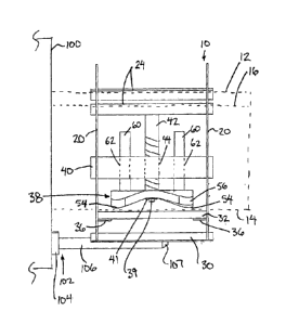
Referring to the accompanying figures, there is illustrated an eavestrough
outlet cutter generally indicated by reference numeral 10. The cutter 10 is
particularly
suited for use with an eavestrough of the type including a generally flat,
vertical rear
5 wall
12, a bottom flange 14 protruding horizontally forward from a bottom edge of
the
rear wall, and a front wall 16 which is sloped upwardly and forwardly from the
forward
edge of the bottom flange. The top edge of the front wall 16 is typically
folded over
inwardly to provide a structurally reinforcing channel at the top edge which
is typically
slightly lower in elevation than a top edge of the opposing rear wall 12.
10 The
outlet cutter 10 includes a main frame which includes two side frame
portions 20 at laterally opposing sides of the cutter. Each side frame portion
comprises
a rigid rectangular plate spanning substantially the full height and full
width of the cutter.
The two plates forming the side frame portions 20 are mounted in parallel,
fixed relation
to one another.
Each side frame portion 20 includes a trough opening 22 formed therein
which is generally U-shaped to match the corresponding profile of the rear
wall, bottom
wall, and front wall of the eavestrough to be slidably received therethrough.
The trough
openings 22 in the two opposing side frame portions 20 are aligned with one
another
such that the trough may be oriented to be received to extend laterally fully
through the
main frame of the cutter in a horizontal orientation with the longitudinal
direction of the
trough being aligned perpendicularly with the two plates forming the side
frame portions
20 of the cutter. The trough openings are slightly oversized relative to the
dimensions
of the trough so as to readily receive the trough therethrough without
interference
between the frame and the trough.
The main frame further includes two upper support channels 24 which
, ,
CA 2967789 2017-05-19
11
span laterally between the two side frame portions 20 in perpendicular
relation to the
side plates to support the side plates in fixed and parallel relation relative
to one
another. The two upper support channels 24 are located in alignment with
opposing
front and rear top ends of the U-shaped profile of the trough openings 22.
Each upper
support channel comprises an angle having a top flange 26 which is
horizontally
oriented for engaging upon the top edge of a corresponding one of the front
wall or rear
wall of the trough, and a side flange 28 depending downwardly from an outer
edge of
the top flange such that the trough is arranged to be located at front and
back walls
thereof between the depending side flanges 28 of the two upper support
channels 24
respectively. The upper support channels 24 are thus arranged such that the
main
frame of the cutter can be suspended on the trough by engagement of the top
flanges
26 onto the top ends of the front wall and rear wall of the trough
respectively so as to
be longitudinally slidable along the length of the trough.
The main frame of the cutter further comprises two lower support
channels 30 which are again fixed to span between the two plates of the side
frame
portions 20 respectively so as to be parallel to one another and perpendicular
to the
side plates in fixed relation therewith. Each lower support channel 30
comprises an
angle of two flanges oriented in an inverted V shape open to the bottom of the
cutter.
The lower support channels 30 are spaced apart along the bottom edges of the
side
frame portions of the cutter adjacent opposing front and rear sides of the
main frame of
the cutter respectively. By locating the lower support channels 30 along the
bottom of
the frame, the support channels 30 are accordingly spaced below the trough
openings
respectively so as not to interfere with sliding support of the frame along a
trough by
engagement of the upper support channels 24 on the top ends of the front and
rear
walls of the trough respectively.
. -
CA 2967789 2017-05-19
12
A female die plate 32 is supported in fixed relation on the main frame. The
die plate 32 comprises a flat plate locating a die opening 34 therein which
defines the
size and generally rectangular shape of the outlet hole cut by the cutter 10.
The die
plate is supported to span horizontally between the two side frame portions 20
at the
bottom of the trough opening such that the die plate 32 is positioned directly
below the
bottom flange 14 of a trough which is slidably received through the frame of
the cutter.
The two side plates forming the side frame portions 20 of the cutter each
support a
respective support flange 36 thereon in the form of a horizontal flange
protruding
inwardly from an inner surface of the respective side plate below the bottom
portion of
the trough opening. Fastener apertures in the two support flanges 36 and at
spaced
apart positions along each of the opposing sides of the die plate 32 permit
threaded
fasteners to secure the opposing edges of the die plate to respective ones of
the support
flanges 36. The threaded fasteners can be readily released to remove the die
plate and
interchange the female die plate with a different die plate having a different
sized die
opening 34 therein as may be desired.
A male die 38 is supported between the two side frame portions 20 so as
to be vertically movable relative to the female die plate 32 between a
disengaged
position spaced above the female die plate, and a punching position fully
received
within the die opening 34 of the female the plate. To support the male die 38,
the main
frame of the cutter includes a cross frame portion 40 which extends laterally
between
the two side frame portions 20 in fixed relation thereto at a location which
is at an
intermediate height relative to the height of the front and rear wall portions
of the trough
opening and which is at a central location relative to the bottom portion of
the trough
openings between the front and rear wall portions of the trough opening.
The male die 38 is supported relative to the cross frame portion by a
CA 2967789 2017-05-19
13
threaded shaft 42 which is vertically oriented at a central location relative
to the die
opening 34 in the female die plate 32 therebelow. The threaded shaft is
threadably
received within a corresponding threaded bore 44 located centrally within the
cross
frame portion 40 such that rotation of the shaft 42 about the upright
longitudinal axis
thereof causes the shaft to be displaced up and down along the axis relative
to the
cross frame portion 40 of the main frame.
The male die 38 comprises a die plate rotatably supported at the bottom
end of the threaded shaft 42. More paiticularly, a reduced diameter portion 39
at the
bottom end of the threaded shaft 42 is received rotatably through a
corresponding sized
bore at a central location within the male die plate 38. The groove is
provided at the
bottom end of the threaded shaft which protrudes from the bottom face of the
male die
to receive a split retainer ring 41 therein which retains the male die plate
rotatably on
the bottom end of the threaded shaft. Releasing the split retainer ring 41
permits the
male die plate to be removed from the threaded shaft and replaced with a
different sized
male die plate so that the male and female die plates can always be replaced
as a
corresponding matching pair with the male die plate matching the size of the
opening
in the female die plate.
The male die plate is similarly shaped to the die opening 34 so as to be
generally rectangular in shape with four corner portions 46 which are rounded
in profile.
The bottom face of the male die plate defines the cutting face of the die. The
bottom
cutting face includes a flat central area 48 from which four corner portions
46 of the
male die protrude outwardly at a downward slope towards the outermost corners
of the
opening to be cut. The four corner portions 46 collectively define the
perimeter cutting
edges of the die which interact in a shearing action with the corresponding
edges of the
die opening 34 of the female die plate.
CA 2967789 2017-05-19
14
Each corner portion 46 of the male die plate is generally triangular in
shape so as to be comprised of two cutting side edges which are sloped
downwardly
and outwardly to a respective apex 52 at the corner which is the lowest point
of the
corner portion respectively.
Two of the corner portions 46, which are diagonally opposed from one
another, are primary cutting tips 54 in which the side edges 50 sloped
downwardly at a
25 angle relative to a horizontal plane of the main portion of the male die
plate so that
the corresponding apexes 52 of the two primary cutting tips form the lowest
points of
the male die plate which are diametrically opposed and which engage the
material to
be cut first.
The other two corner portions 46 define secondary cutting tips 56 in which
the side edges 50 are sloped downwardly at a 200 angle relative to the
horizontal plane
of the main portion of the male die plate so that the corresponding apexes 52
of the two
secondary tips are at the same elevation relative to one another which
corresponds to
an elevation at an intermediate location along the sloped side edges 50 of the
two
primary cutting tips.
The male die plate is further supported by two support posts 60 which are
laterally spaced apart at diametrically opposed sides of the threaded shaft 42
so as to
be fixed to protrude vertically upward from the top side of the male die plate
38 in
parallel relation with the threaded shaft .42. Corresponding bores 62 in the
cross frame
portion of the main frame, at diametrically opposing sides of the threaded
bore receiving
the shaft 42 therein, slidably received the support posts 60 therethrough as
the male
die plate is displaced up and down by the rotation of the threaded shaft
relative to the
main frame.
The outlet cutter 10 is particularly suited for use with a trough bender 100
CA 2967789 2017-05-19
of the type used for forming eavestroughs from flat sheet metal material. The
flat sheet
metal material is typically available in a roll on a drum or reel so that the
flat sheet can
be unrolled and fed into the inlet side of the trough bender 100. The trough
bender
includes a plurality of roll-forming rollers supported within the housing of
the bender that
5 form the flat sheet metal received at the inlet side of the housing into
the eavestrough
shape described above having a flat rear wall 12 a bottom flange 14 and a
front sloped
wall 16. The trough bender is capable of continuously forming the eavestrough
shape
as flat sheet metal is inserted into the inlet side of the trough bender and
the formed
eavestrough exits through an opposing outlet side of the housing.
10 The outlet cutter is intended to be supported at the outlet end of
the
housing of the trough bender 100 in alignment with the exit location of the
formed
eavestrough. When the outlet cutter is not in use, it can remain supported on
the outlet
end of the housing and not interfere with the eavestrough being formed which
merely
passes fully through the frame of the outlet cutter by being received in the
trough
15 openings 22.
In order to support the outlet cutter at the outlet end of the trough bender
100 so that the formed eavestrough can pass through the cutter frame without
contacting the cutter, a suitable storage mount 102 is provided. The storage
mount
includes a mounting plate 104 which supports two rails 106 protruding
perpendicularly
outward therefrom at parallel and spaced apart positions corresponding to the
space
between the two lower support channe[s 30 of the cutter. Each support rail
comprises
a round rod having a length corresponding approximately to the width of the
cutter
frame in the lateral direction between the two side frame portions 20. The
free ends 107
of the support rails 106 are tapered for ease of sliding the cutter frame onto
the support
rails 106 when sliding the cutter frame along an eavestrough exiting a trough
bender.
CA 2967789 2017-05-19
16
The mounting plate 104 includes fastener holes therein to permit threaded
fasteners to
secure the mounting plate to the outlet end of the trough bender. The mounting
location
of the storage mount is selected such that when the support rails 106 are
received
within the two lower support channels 30 engaged thereon, the cutter frame is
entirely
supported on the support rails and the trough openings in the side frame
portions of the
cutter are aligned with the exit location of the eavestrough exiting the
trough bender to
enable the exiting eavestrough to pass fully through the trough openings in
the cutter
without contacting the cutter.
When it is desired to cut an outlet opening in the eavestrough, the user
merely slides the cutter 10 off of the, support rails 106 and continues to
slide the cutter
in the longitudinal direction along the trough while the upper support
channels 24 are
supported on the top edges of the front and rear walls respectively. The
cutter is then
aligned in the longitudinal direction of the trough with the desired location
of an outlet
to be cut.
The top end of the threaded shaft 42 which protrudes above the cross
frame portion 40 is formed to include a socket 64 therein which has a
hexagonal cross-
section sized to mate with the conventional hexagonal cross-section of the
mounting
end of various screw driver bits 65 adapted for being received in common
commercially
available electric power drills used in the construction industry. The socket
64 has a
depth in the axial direction which is greater than the length of the bit
portion 67 of the
screw driver bit so that the hexagonal mounting end 69 of the screw driver bit
can mate
with the hexagonal cross section of the,socket 64 of the cutter 10 when the
bit portion
is fully inserted into the socket 64. Operating the drill in forward and
reverse directions
will rotate the threaded shaft 42 in corresponding forward and reverse
directions for
displacing the male die 38 towards and away from the female die 32
respectively.
CA 2967789 2017-05-19
,
17
When performing a punching operation, the two primary cutting tips 54
are the first point of engagement of the male die with the bottom flange of
the trough to
begin cutting at two diagonally opposed locations. Once the two primary
cutting tips
are partially penetrated through the bottom flange of the trough, the two
secondary
cutting tips 56 then engage the bottom flange of the trough at respective
apexes of the
secondary cutting tips. Before punching, the female die is spaced below the
upper
channels 24 so as to be spaced slightly below the bottom flange of the trough
to provide
a clearance gap which allows the trough to be freely slid through the trough
openings
when the device 10 is stored on the rails 106 on a trough bender. Once the
primary
.. cutting tips engage the top side of the bottom of the trough after initial
rotation to begin
a punching operation, continued rotation of the shaft 42 acts to lift the
frame with the
female die supported thereon relative to the trough until the female die is in
firm
engagement with the bottom side of the trough. Continued actuation of the
drill will
complete the punching action by fully penetrating all four corner portions and
the full
perimeter cutting edge of the male die fully through the bottom flange of the
eavestrough and into the female die opening. The last four portions of the
outlet
opening to be cut include an intermediate segment at a central location along
each of
the four sides of the generally rectangular shape of the outlet opening.
Reversing
operation of the drill will return the male die to the disengaged position
such that the
outlet cutter can be slid along the trough back to a storage position engaged
upon the
rails of the storage mount. The trough can continue to be continuously formed
by the
bender such that the formed trough continues to exit the bender by being
received in a
non-contacting manner through the trough openings of the cut.
When the cutting of the bottom flange is complete, and the male die is
fully received within the die opening of the female die, the frame of the
cutter device
CA 2967789 2017-05-19
18
and the female die supported thereon drop back down until the channels 24
engage
the top edges of the trough, indicating that the hole has been cut. The
operator can
then reverse the drill to return the male die to a starting position spaced
above the
female die. The shape of male die 38, not only cuts a blank piece (or plug)
out of the
bottom flange of the trough, but also bends the edges of the plug inward,
making it
smaller in dimension than the rectangular hole in the female die 32 such that
the plug
doesn't get stuck in die 32 and simply falls out the bottom of the cutting
device. No
additional spring mechanism is required to eject the plug as in prior art
designs of trough
outlet cutters.
Since various modifications can be made in my invention as herein above
described, and many apparently widely different embodiments of same made, it
is
intended that all matter contained in the accompanying specification shall be
interpreted
as illustrative only and not in a limiting sense.
,