Note: Descriptions are shown in the official language in which they were submitted.
CA 2967923 2017-05-23
51179
METERING SYSTEM FOR AN AGRICULTURAL SYSTEM
BACKGROUND
[0001] The present disclosure relates generally to a metering system for an
agricultural system, and more particularly to a metering system for plantlet
casings.
[0002] Generally, seeding implements (e.g., seeders, planters) are towed
behind or
semi-mounted on a tractor or other work vehicle via a mounting bracket secured
to a
rigid frame of the implement. Seeding implements typically include multiple
row
units distributed across a width of the implement. Each row unit is configured
to
deposit seeds at a desired depth beneath the soil surface of a field, thereby
establishing rows of planted seeds. For example, each row unit typically
includes a
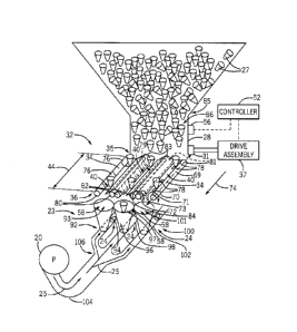
ground engaging tool or opener that forms a seeding path (e.g., trench) for
seed
deposition into the soil. A seed tube (e.g., coupled to the opener) is
configured to
deposit seeds and/or other agricultural products (e.g., fertilizer) into the
trench. The
opener/seed tube is followed by closing discs that move displaced soil back
into the
trench and/or a packer wheel that packs the soil on top of the deposited
seeds.
[0003] In certain agricultural system configurations, an air cart is used
to meter
and deliver agricultural product (e.g., seeds, fertilizer, etc.) to the row
units of the
seeding implement. The air cart generally includes a storage tank (e.g., a
pressurized
tank), an air source (e.g., a blower), and a metering system. The agricultural
product
is typically gravity fed from the storage tank to the metering system, which
distributes
a desired volume of agricultural product into an air flow generated by the air
source.
The air flow carries the product to the row units via conduits extending
between the
air cart and the seeding implement. The metering system typically includes
meter
rollers that regulate the flow of product based on meter roller geometry and
rotation
rate. Unfortunately, typical meter rollers may not be effective at metering
casings that
include plantlets from the storage tank to the row units. For example,
plantlets may
be disposed in casings (e.g., plantlet casings), which may not flow through
typical
metering systems.
1
CA 2967923 2017-05-23
51179
BRIEF DESCRIPTION
[0004] In one embodiment, a metering system for an agricultural system
includes a
singulator. The singulator includes a hopper configured to provide a flow of
plantlet
casings from a storage tank of the agricultural system, a pair of counter-
rotating rods
configured to receive the plantlet casings from the hopper at a feed rate,
where the
pair of counter-rotating rods are spaced apart from one another to form a gap,
and
where the gap is configured to direct the plantlet casings from a first end of
the pair of
counter-rotating rods to a second end of the pair of counter-rotating rods,
and a drive
assembly configured to drive rotation of the pair of counter-rotating rods.
[0005] In another embodiment, a metering system for an agricultural system
includes a singulator and an inductor. The singulator includes a pair of
counter-
rotating rods configured to receive plantlet casings from a storage tank of
the
agricultural system at a feed rate, where the pair of counter-rotating rods
are spaced
apart from one another to form a gap, and where the gap is configured to
direct the
plantlet casings from a first end of the pair of counter-rotating rods to a
second end of
the pair of counter-rotating rods, and a drive assembly configured to drive
rotation of
the pair of counter-rotating rods. The inductor includes a receiving portion
configured to receive the plantlet casings from the second end of the counter-
rotating
rods of the singulator, a conduit coupled to the receiving portion and
configured to
receive the plantlet casings from the receiving portion, where the conduit is
configured to convey the plantlet casings to at least one row unit, and an air
source
fluidly coupled to the conduit and configured to provide an air flow through
the
conduit to convey the plantlet casings to the at least one row unit.
[0006] In another embodiment, a metering system for an agricultural system
includes a singulator. The singulator includes a plurality of pairs of counter-
rotating
rods configured to receive plantlet casings from a storage tank of the
agricultural
system at a feed rate, where each pair of counter-rotating rods of the
plurality of pairs
of counter-rotating rods is spaced apart from one another to form a gap, and
where the
gap is configured to direct the plantlet casings from a first end of the
plurality of pairs
2
CA 2967923 2017-05-23
51179
of counter-rotating rods to a second end of the plurality of pairs of counter-
rotating
rods, and a drive assembly configured to drive rotation of at least one pair
of counter-
rotating rods of the plurality of pairs of counter-rotating rods.
DRAWINGS
[0007] These and other features, aspects, and advantages of the present
disclosure
will become better understood when the following detailed description is read
with
reference to the accompanying drawings in which like characters represent like
parts
throughout the drawings, wherein:
[0008] FIG. 1 is a side view of an embodiment of an air cart, including a
metering
system configured to regulate a flow of plantlet casings, in accordance with
an aspect
of the present disclosure;
[0009] FIG. 2 is a schematic view of an embodiment of a metering system
that
may be employed within the air cart of FIG. 1, in accordance with an aspect of
the
present disclosure;
[0010] FIG. 3 is a perspective view of an embodiment of a singulator of the
metering system of FIG. 2, in accordance with an aspect of the present
disclosure;
[0011] FIG. 4 is a schematic view of an embodiment of an inductor of the
metering
system of FIG. 2, in accordance with an aspect of the present disclosure; and
[0012] FIG. 5 is a flow chart of an embodiment of a process that may be
used to
adjust a speed of the singulator of FIG. 3, in accordance with an aspect of
the present
disclosure.
DETAILED DESCRIPTION
[0013] The embodiments disclosed herein relate to an improved metering
system
that is configured to meter plantlets enclosed in casings. For example, it may
be
desirable to dispose plantlets into the ground to produce certain types of
agricultural
products (e.g., agricultural products that are difficult to grow using seeds).
As used
3
CA 2967923 2017-05-23
51179
herein, "plantlets" refer to partially grown plants (e.g., plants that have
not fully
matured). Plantlets may be grown in a greenhouse, garden, laboratory, or
another
preliminary growing location and transported to a commercial farm where more
space
is available to produce a large quantity of the mature plants. In order to
facilitate,
storage, transportation, and disposal of the plantlets into the ground (e.g.,
soil), the
plantlets may be enclosed in casings. In some embodiments, the plantlet
casings may
include an inverted frustum-shape (e.g., cone-shape) and have a greater weight
at a
first end (e.g., a narrower end) as compared to a second end (e.g., a wider
end) to
facilitate disposing the plantlet casings into the ground. For example, the
plantlet,
soil, fertilizer, water, other organic material, or a combination thereof, may
be
disposed in the first end (e.g., the narrower end). Additionally, the first
end of the
inverted frustum-shape may have a first diameter smaller than a second
diameter of
the second end. Accordingly, the plantlet casings may be substantially self-
orienting
(e.g., with the first end down and the second end up) to ensure that the
plantlet is
properly oriented in the ground. In other embodiments, the plantlet casings
may
include any other suitable shape (e.g., spherical, polygonal, or another shape
configured to facilitate storage, transport, and planting of the plantlet). In
accordance
with embodiments of the present disclosure, the plantlet casings are
configured to be
disposed into a furrow that may be formed by openers of traditional seeders.
The
plantlet casings may be biodegradable, such that over time, the plantlets may
be
exposed to the surrounding soil, such that the plantlets may grow into mature
plants.
[0014] Unfortunately, typical air carts are intended to handle seed
particles, which
are relatively small when compared to the plantlet casings. Therefore, typical
air carts
may not be configured to meter plantlet casings effectively. It is now
recognized that
an improved metering system is desired to convey a large quantity of the
plantlet
casings to row units to facilitate depositing the plantlet casings into the
ground.
[0015] Embodiments of the present disclosure relate to a metering system
that
includes a singulator and/or an inductor assembly that are configured to
convey the
plantlet casings from a storage tank to row units of a seeder. The singulator
may
include one or more pairs of counter-rotating rods that direct the plantlet
casings from
an outlet of the storage tank (e.g., a hopper) to an inlet (e.g., opening) of
one or more
4
CA 2967923 2017-05-23
51179
inductors of the inductor assembly. In some cases, the one or more pairs of
counter-
rotating rods may be positioned at a downward sloping angle with respect to
the
ground to use gravity, in addition to the counter-rotation of the rods, to
singulate and
convey the plantlet casings. In any case, the counter-rotation of the rods may
singu late and direct the plantlet casings toward the one or more inductors at
a selected
rate. The selected rate may be adjusted based on a vibration frequency of the
hopper
and/or a speed of an air source that is configured to convey the plantlet
casings
through the inductor assembly toward the row units. For example, the selected
rate,
the vibration frequency of the hopper, and/or the speed of the air source may
be set
based on a target flow rate of the plantlet casings through the metering
system. In
some embodiments, the selected rate may be adjusted by controlling an amount
of
power supplied to the one or more pairs of counter-rotating rods using a drive
assembly. The amount of power supplied to the one or more pairs of counter-
rotating
rods may be proportional to the rotation speed of the one or more pairs of
counter-
rotating rods. Accordingly, the drive assembly may be attached to the one or
more
pairs of counter-rotating rods and to a controller (e.g., a variable frequency
drive) to
control an amount of power supplied to the one or more pairs of counter-
rotating rods,
and thus, the speed of the one or more pairs of counter-rotating rods.
[0016] When the
plantlet casings reach an end of each pair of counter-rotating
rods, the plantlet casings move into an inductor of the inductor assembly.
Each
inductor of the inductor assembly may include an inlet (e.g., opening) having
a
funnel-shape to facilitate receiving the plantlet casings into the inductor.
The inductor
may convey the plantlet casings toward a respective row unit or group of row
units
via an air flow generated from an air source. In some embodiments, each
inductor of
the inductor assembly may include a physical feature (e.g., a portion of the
conduit
having a smaller diameter, a check valve, or another suitable feature) that
blocks
movement of the inverted frustum-shaped casings toward the air source. The
inductor
may include an opening having a diameter sufficiently large to accommodate a
size of
the plantlet casings and any variations between sizes of the plantlet casings
due to
engineering and/or manufacturing tolerances. Accordingly, each inductor of the
inductor assembly may direct the plantlet casings to the respective row unit
or group
CA 2967923 2017-05-23
51179
of row units, such that the plantlet casings may be disposed in the ground to
ultimately grow into mature plants.
[0017] To help illustrate the manner in which the present embodiments may
be
used in a system, FIG. 1 is a side view of an agricultural system 9 that
includes an air
cart 10, which may be used in conjunction with a towable agricultural
implement 11
to deposit plantlets enclosed in casings (e.g., plantlet casings) into the
soil. As used
herein, the agricultural system 9 refers to a system that includes the air
cart, the
agricultural implement, a work vehicle, or a combination thereof. Certain
agricultural
implements include row units that may be configured to open the soil (e.g.,
via a
planter shoe, a double disc opener, a hoe opener, or the like), dispense
plantlet casings
into the soil opening, and re-close the soil. Such implements 11 are generally
coupled
to a tow vehicle, such as a tractor, and pulled through a field. In accordance
with
embodiments of the present disclosure, plantlet casings are conveyed to the
row units
by the illustrated air cart 10, which is generally towed in sequence with the
implement
along a direction of travel 12. In certain configurations, the air cart 10 may
be
configured to provide a combination of plantlet casings and fertilizer.
[0018] In the illustrated embodiment, the air cart 10 includes a storage
tank 13, a
frame 14, wheels 16, a metering system 18, and an air source 20. In certain
configurations, the storage tank 13 includes multiple compartments for storing
various
flowable particulate materials (e.g., the plantlet casings, fertilizer, etc.).
For example,
one compartment may include the plantlet casings, which may include sugar cane
plantlets, willow plantlets, poplar plantlets, grape plantlets, miscanthus
plantlets,
potato plantlets, rhizome-based plantlets, among others, and another
compartment
may include a fertilizer. In such configurations, the air cart 10 is
configured to deliver
both the plantlet casings and fertilizer to the implement (e.g., row units of
the
implement). The frame 14 includes a towing hitch configured to couple to the
implement or tow vehicle. As discussed in detail below, plantlet casings
and/or
fertilizer within the storage tank 13 are gravity fed into the metering system
18 (e.g.,
via a hopper). In some embodiments, the metering system 18 includes a
singulator
that regulates the flow of material (e.g., plantlet casings, fertilizer, etc.)
from the
storage tank 13 into an inductor assembly that directs material to the
implement (e.g.,
6
CA 2967923 2017-05-23
51179
row units of the implement) via air flow provided by the air source 20. For
example,
the air flow carries the material (e.g., plantlet casings, fertilizer, etc.)
to the implement
in pneumatic conduits. In this manner, the row units receive a supply of
plantlet
casings and/or fertilizer for deposition into the soil.
[0019] FIG. 2 is a schematic view of the metering system 18 of FIG. 1, in
accordance with an aspect of the present disclosure. As illustrated, the air
source 20
is fluidly coupled to a conduit 22 of an inductor assembly 23 that includes
one or
more inductors 24. The conduit 22 is configured to flow air 25 through the
inductor
assembly 23. The air source 20 may be a pump or blower powered by an electric
or
hydraulic motor, for example. Flowable particulate material 26 (e.g., plantlet
casings
27, etc.) within the storage tank 13 flows by gravity into the metering system
18. In
the illustrated embodiment of FIG. 2, the storage tank 13 includes a hopper 28
at an
outlet 30 of the storage tank 13. The hopper 28 may be configured to vibrate,
such
that material in the storage tank 13 shifts and falls from the outlet 30 of
the storage
tank 13 to the metering system 18 at a substantially constant rate. For
example, the
hopper 28 may include a shaker 31 configured to vibrate the hopper 28 and
shift the
plantlet casings 27, such that the plantlet casings 27 fall from the storage
tank 13.
Additionally or alternatively, the storage tank 13 may be pressurized such
that a static
pressure in the storage tank 13 is greater than a static pressure in the
conduit 22,
thereby facilitating an even flow of material through the metering system 18.
The
metering system 18 includes a singulator 32 and the inductor assembly 23.
10020] In some embodiments, the singulator 32 may include one or more pairs
of
counter-rotating rods 34. The one or more pairs of counter-rotating rods 34
are
configured to singulate and direct the material (e.g., plantlet casings and/or
fertilizer)
from the storage tank 13 to the inductor assembly 23. For example, a first end
35 of
the one or more pairs of counter-rotating rods 34 may receive the material 26
from the
storage tank 13 (or the hopper 28) and a second end 36 of the one or more
pairs of
counter-rotating rods 34 may direct the material 26 toward the inductors 24 of
the
inductor assembly 23. In some embodiments, each pair of the one or more pairs
of
counter-rotating rods 34 may be associated with a respective inductor 24 of
the
inductor assembly 23.
7
CA 2967923 2017-05-23
51179
[0021] In the illustrated embodiment, the one or more pairs of counter-
rotating
rods 34 are coupled to a drive assembly 37, which is configured to rotate the
one or
more pairs of counter-rotating rods 34 (e.g., in both clockwise and
counterclockwise
directions). In certain embodiments, the drive assembly 37 may include an
actuator
38, such as an electric or hydraulic motor, configured to drive the one or
more pairs of
counter-rotating rods 34 to rotate. In further embodiments, the drive assembly
37
may be coupled to one or more of the wheels 16 (e.g., via a gear assembly)
such that
rotation of the wheels 16 drives the one or more pairs of counter-rotating
rods 34 to
rotate. Such a configuration automatically varies the rotation rate of the one
or more
pairs of counter-rotating rods 34 based on a speed of the air cart 10. In
still further
embodiments, the drive assembly 37 may drive the one or more pairs of counter-
rotating rods 34 to rotate at different speeds (e.g., each pair of the one or
more pairs of
counter-rotating rods 34 rotates at a speed independent of the remaining one
or more
pairs of counter-rotating rods 34) based on a target flow rate of a respective
row unit
or group of row units. Additionally, in some embodiments, the drive assembly
37
may be configured to supply power to the air source 20.
[0022] A gap 40 is positioned between each pair of counter-rotating rods
34.
Accordingly, the material exiting the hopper 28 (and the storage tank 13) may
fall into
the gap 40 between each pair of counter-rotating rods 34. In some embodiments,
the
gap 40 may have a width that is less than a first diameter 42 of the plantlet
casings 27,
but greater than a second diameter 43 of the plantlet casings 27. In other
embodiments, the width of the gap 40 may increase throughout a length 44 of
each
pair of counter-rotating rods 34 from a first end 45 to a second end 46 (e.g.,
the width
increases moving away from the storage tank 13). In any case, the width of the
gap
40 may be less than the first diameter 42 of the plantlet casings 27 to block
the
plantlet casings 27 from falling between the pair of counter-rotating rods 34.
Additionally, a guide may be disposed over each pair of counter rotating rods
34, such
that the plantlet casings 27 are directed into a respective gap 40 between a
pair of the
one or more pairs of counter-rotating rods 34. Accordingly, the plantlet
casings may
be blocked from falling directly onto a rod of the one or more pairs of
counter-
rotating rods 34.
8
CA 2967923 2017-05-23
51179
[0023] As shown in
the illustrated embodiment, the one or more pairs of counter-
rotating rods 34 are oriented at an angle 47 to a horizontal plane 48 (e.g.,
parallel to
ground 49). For example, the angle 47 may be between approximately 0 to 60
degrees, approximately 0 to 45 degrees, approximately 0 to 30 degrees, or
approximately 0 to 15 degrees relative to the horizontal plane 48, which is
parallel to
the ground 49.
[0024] In some
embodiments, a rotation rate of the one or more pairs of counter-
rotating rods 34 controls the flow rate of material 26 into the air stream 25.
Accordingly, the rotation rate of the one or more pairs of counter-rotating
rods 34
may be adjusted by a controller 52, which is communicatively coupled to the
drive
assembly 37, based on a target flow rate of the material 26 into the soil.
Additionally,
the controller 52 may adjust a speed of the air source 20, such that the air
flow 25 is
sufficient to meet the target flow rate of material 26 into the soil. Further,
a vibration
frequency of the hopper 28 may also be adjusted to reach the target flow rate
of the
material 26 into the soil. In some
embodiments, the controller 52 may receive
feedback from one or more sensors that are configured to measure parameters of
the
metering system 18. For example, the controller 52 may receive feedback from a
flow sensor 54 disposed in the conduit 22, such that the controller 52 may
determine
the flow rate of the air stream 25 and adjust the flow rate of the air stream
25 based on
the target flow rate of material 26 into the soil.
[0025] Additionally,
the controller 52 may be coupled to a piezoelectric sensor 56
and/or another sensor that may measure the vibration frequency of the hopper
18.
The controller 52 may be configured to adjust the vibration frequency of the
hopper
18 (e.g., via the shaker 31) based on the target flow rate of the material 26
into the
soil. Further, in some embodiments, the controller 52 may be configured to
adjust
the rotation rate of the one or more counter-rotating rods 34 based on the
flow rate of
the air stream 25, the vibration frequency of the hopper 18, and/or the target
flow rate
of the material 26 into the soil.
9
CA 2967923 2017-05-23
51179
[0026] As the one or more pairs of counter-rotating rods 34 rotate, a pair
of the one
or more pairs of counter-rotating rods 34 transfer plantlet casings 27 in the
gap 40
between the pair of counter-rotating rods 34 to a receiving portion 58 (e.g.,
inlet) of a
respective inductor 24 of the inductor assembly 23. At the end of the rods,
the
plantlet casings 27 fall through the receiving portion 58 and are directed
into
respective conduit(s) 22 associated with a respective row unit or group of row
units
fluidly coupled to the inductor 24. The plantlet casings 27 are then directed
to the
respective row unit(s) of the implement through pneumatic conduits via the air
flow
25. From the respective row unit(s), the plantlet casing 27 may be disposed
into the
soil.
[0027] FIG. 3 is a perspective view of the singulator 32 of FIG. 2,
illustrating
operation of the one or more pairs of counter-rotating rods 34, in accordance
with
embodiments of the present disclosure. As shown in the illustrated embodiment,
the
singulator 32 includes three pairs of counter-rotating rods 34. In other
embodiments,
the singulator 32 may include one, two, four, five, six, seven, eight, nine,
ten, or more
pairs of the counter-rotating rods 34. Each pair of counter-rotating rods 34
includes a
first rod and a second rod, in which the first rod rotates in a first
direction about a
longitudinal axis 69 of the rods (e.g., clockwise or counterclockwise) and the
second
rod rotates in a second direction about the longitudinal axis 69 of the rods
(e.g.,
clockwise or counterclockwise), opposite the first direction. For example, a
rod 70 of
the one or more pairs of counter-rotating rods 34 may rotate in a first
direction 71, and
an adjacent rod 72 of the one or more pairs of counter-rotating rods 34 may
rotate in a
second direction 73, opposite the first direction 71. Counter-rotation of the
pairs of
counter-rotating rods 34 may direct the plantlet casings 27 toward the
receiving
portions 58 of the respective inductors 24 of the inductor assembly 23 in a
direction
74.
[0028] In the illustrated embodiment, the pairs of counter-rotating rods 34
include
grooves 76 and/or protrusions 78 configured to hold the plantlet casings 27
between
each pair of counter-rotating rods 34. For example, the grooves 76 and
protrusions 78
are spaced along the length 44 of the one or more pairs of counter-rotating
rods 34
such that only one of the plantlet casings 27 may fit between adjacent grooves
76 and
CA 2967923 2017-05-23
51179
adjacent protrusions 78. In other embodiments, the one or more pairs of
counter-
rotating rods 34 may include a screw configuration 79 (e.g., a helical recess)
also
configured to hold the plantlet casings 27 between a pair of the one or more
pairs of
counter-rotating rods 34. As shown in the illustrated embodiment, a first pair
80 of
the counter-rotating rods 34 may include the grooves 76, a second pair 81 of
the
counter-rotating rods 34 may include the protrusions 78, and a third pair 82
of the
counter-rotating rods 34 may include the screw configuration 79. While the
illustrated embodiment, shows the pairs 80, 81, and 82 having the grooves 76,
protrusions 78, and screw configuration 79, respectively, it should be noted
that the
pairs 80, 81, and/or 82 may include the grooves 76, the protrusions 78, the
screw
configuration 79, or a combination thereof.
[0029] Additionally, in the illustrated embodiment, the one or more pairs
of
counter-rotating rods 34 include guides 83 disposed over certain rods of the
one or
more pairs of counter-rotating rods 34. The guides 83 are configured to
substantially
block the plantlet casings 27 from being disposed directly onto adjacent rods
of the
one or more pairs of counter-rotating rods 34. For example, the guide 83 may
cover a
the rod 70 of the one or more counter-rotating rods 34 and an adjacent rod 84
of the
one or more counter-rotating rods 34. Accordingly, the guide 83 is configured
to
direct the plantlet casings 27 into the gap 40 between the pairs 81 and 82 of
the one or
more pairs of counter-rotating rods 34. Disposing the plantlet casings 27 into
the gap
40 (e.g., instead of onto adjacent rods of the one or more pairs of counter-
rotating rods
34) may ensure that the plantlet casings 27 move toward the receiving portions
58 of
the inductor assembly 23 and the plantlet casings 27 do not get stuck on top
of
adjacent rods of the one or more pairs of counter-rotating rods 34.
Additionally, the
guides 83 may act to guide the plantlet casings 27 into a specific gap 40,
such that a
flow rate of the plantlet casings 27 toward the receiving portions 58 is
substantially
constant (e.g., block plantlet casings 27 from moving from one gap 40 to
another gap
40 due to vibrations experienced during movement of the air cart 10).
100301 As shown in the illustrated embodiment, a bottom portion 85 of the
storage
tank 13 is coupled to the hopper 28. The hopper 28 includes a single
compartment 86
that directs the plantlet casings 27 to each pair of counter-rotating rods 34.
In other
11
CA 2967923 2017-05-23
51179
embodiments, the hopper 28 may include multiple compartments, in which each
compartment is configured to direct the plantlet casings 27 to a corresponding
pair of
the one or more pairs of counter-rotating rods 34.
[0031] As discussed above, the hopper 28 may vibrate at a frequency that
enables
the plantlet casings 27 to flow from the storage tank 13 at a substantially
constant rate.
Vibration of the hopper 28 may be driven by the shaker 31, which may be
controlled
by the drive assembly 37 or another actuating device. In some cases, the
vibration
frequency of the hopper 28 may vary due to fluctuations in a signal to the
shaker 31,
which drives the hopper 28 to vibrate. In some embodiments, the vibration
frequency
of the hopper 28 may be adjusted to achieve the target flow rate of the
material 16
into the soil. In other embodiments, the rotation rate of the one or more
pairs of
counter-rotating rods 34 may be adjusted by the controller 52 based on
feedback
received by the controller 52 indicative of the vibration frequency of the
hopper 18.
[0032] The plantlet casings 27 are directed from the first end 35 of the
one or more
pairs of counter-rotating rods 34 along the length 44 to the second end 36 of
the one
or more pairs of counter-rotating rods 34. Each receiving portion 58 is
located at or
near the second end 36 of a respective pair of counter-rotating rods 34. For
example,
in the illustrated embodiment, the inductor assembly 23 includes three
inductors 24,
and thus, three of the receiving portions 58, which correspond to three
respective pairs
of counter-rotating rods 34. As discussed above, the metering system 18 may
include
more than three pairs of counter-rotating rods 34. Thus, the inductor assembly
23 of
the metering system 18 may include a corresponding number of inductors 24 and
receiving portions 58.
[0033] As shown in the illustrated embodiment, a first inductor 92 includes
a first
receiving portion 93 of the receiving portions 58 that directs the plantlet
casings 27
into a first conduit 94, which leads to a first row unit or group of row
units.
Additionally, a second inductor 96 includes a second receiving portion 97 of
the
receiving portions 58 that directs the plantlet casings 27 into a second
conduit 98,
which leads to a second row unit or group of row units. Further, a third
inductor 100
includes a third receiving portion 101 of the receiving portions 58 that
directs the
12
CA 2967923 2017-05-23
51179
plantlet casings 27 into a third conduit 102, which leads to a third row unit
or group of
row units. Despite the fact that each of the receiving portions 93, 97, 101
directs the
plantlet casings 27 into a separate conduit (and thus to a different row unit
or group of
row units), a single air source 20 may be utilized to convey the plantlet
casings 27
through each of the conduits 94, 98, 102. For example, the air source 20 may
direct
the air flow 25 through a primary conduit 104 toward a split 106 in the
primary
conduit 104 that divides the primary conduit 104 into the first conduit 94,
the second
conduit 98, and/or the third conduit 102. Accordingly, the air flow 25 from
the air
source 20 may flow into the first conduit 94, the second conduit 98, and the
third
conduit 102, such that the plantlet casings 27 may be directed from the
receiving
portions 93, 97, and/or 101 to the first, second, and third row units or
groups of row
units, respectively. In some embodiments, the air source 20 may be configured
to
provide sufficient air flow 25 to each of the conduits 94, 98, and 102, such
that the
plantlet casings 27 are directed through each of the conduits 94, 98, and 102
to the
row units substantially simultaneously.
[00341 FIG. 4 is a cross-sectional view of one inductor 24 of the inductor
assembly
23, illustrating a path 120 of the plantlet casings 27 from the receiving
portion 58 to a
row unit 122. For example, the plantlet casings 27 may be gravity fed into the
receiving portion 58 (e.g., fall from the second end 36 of a pair of counter-
rotating
rods 34 into the receiving portion 58 via gravitational force). In the
illustrated
embodiment, the receiving portion 58 has a first diameter 124 that is greater
than the
first diameter 42 of the plantlet casings 27, such that the receiving portion
58 may
receive the plantlet casings 27.
[0035] The receiving portion 58 also includes a second diameter 126 at an
aperture
128 in the conduit 22. In some embodiments, the second diameter 126 of the
receiving portion 58 may be less than the first diameter 124 of the receiving
portion
58, such that the receiving portion 58 guides the plantlet casings 27 from a
first end
130 of the receiving portion 58 to a second end 132 of the receiving portion
58 (e.g.,
the second end 132 is at the aperture 128). For example, the illustrated
receiving
portion 58 is substantially cone-shaped, such that the receiving portion 58
funnels the
plantlet casings 27 into the conduit 22. The second diameter 126 of the
receiving
13
CA 2967923 2017-05-23
51179
portion 58 may be greater than the first diameter 42 of the plantlet casings
27 and a
length 134 of the plantlet casings 27, such that the possibility of the
plantlet casings
27 blocking the aperture 128 in the conduit 22 is substantially reduced or
eliminated.
As discussed above, the plantlet casings 27 may have an inverted frustum-shape
with
a heavier weight on a first end 136. Therefore, the configuration of the
plantlet
casings 27 may cause the plantlet casings 27 to be oriented substantially
vertically
with the first end 136 down as the plantlet casings 27 fall through the
receiving
portion 58. In addition, the configuration of the plantlet casings 27 may
cause the
plantlet casings 27 to be oriented with the first end 136 in front of a second
end 140
with respect to a direction of flow of the plantlet casings 27 along the path
120.
[0036] The plantlet casings 27 may be gravity fed from the receiving
portion 58
into the conduit 22 (e.g., the plantlet casings 27 fall from the receiving
portion 58 and
into the conduit 22 via gravitational forces). Once the plantlet casings 27
reach the
conduit 22, the air flow 25 directs the plantlet casings 27 along the path 120
toward
the row unit 122. The air source 20 may generate a sufficient air flow
configured to
convey multiple plantlet casings 27 through the conduit 22 (e.g., one, two,
three, four,
five, six, seven, eight, nine, ten, or more plantlet casings).
[0037] As shown in the illustrated embodiment, the conduit 22 includes a
physical
feature 142 located upstream of the aperture 128 with respect to the path 120
of the
plantlet casings 27. In the illustrated embodiment, the physical feature 142
is a
portion of the conduit 22 that has a diameter 144 smaller than a diameter 146
of the
remainder of the conduit 22. In some cases, the diameter 144 may be less than
the
first diameter 42 of the plantlet casings 27, such that the plantlet casings
27 are
blocked from moving from the aperture 128 toward the air source 20. In the
illustrated embodiment, the physical feature 142 also includes a check valve
147 that
blocks flow of any material (e.g., plantlet casings, fertilizer, air, etc.) in
a direction
148 from the aperture 128 toward the air source 20. In other embodiments, the
physical feature 142 may be another valve or restriction disposed along the
conduit
22.
14
CA 2967923 2017-05-23
51179
[0038] FIG. 5 is a flow chart of an embodiment of a process 170 that may be
utilized to adjust the vibration frequency of the hopper, the flow rate of the
air flow
through the conduit, and/or the rotation speed of the one or more pairs of
counter-
rotating rods. For example, at block 172, the controller may receive inputs
indicative
of a target flow rate of plantlet casings to soil. In some embodiments, the
inputs may
include a target spacing between plantlet casings (e.g., a target spacing of
the plantlet
casings in the soil along the path of the agricultural system), a target speed
of the row
units or group of row units, and/or a number of row units or group of row
units of the
implement. Accordingly, the controller may utilize the inputs to determine the
target
flow rate of plantlet casings to the soil. Additionally, the controller may
receive
feedback from one or both of the flow sensor and the piezoelectric sensor to
determine a measured vibration frequency of the hopper and/or a measured air
flow
rate through the conduit of the inductor assembly, as shown in block 174. For
example, the controller may be communicatively coupled to the piezoelectric
sensor
and/or the flow sensor, such that the piezoelectric sensor and/or the flow
sensor
provide feedback to the controller. The controller may then utilize the
feedback to
determine the measured vibration frequency and/or the measured air flow rate
through
the conduit of the inductor assembly.
[0039] At block 176, the controller may determine a measured rotation speed
of
the one or more pairs of counter-rotating rods. For example, the controller
may be
communicatively coupled to a rotation speed sensor (e.g., a reflective sensor,
an
interrupter sensor, a variable-reluctance sensor, an eddy-current killed
oscillator, a
Wiegand sensor, a Hall-effect sensor, a tachometer, another sensor configured
to
measure a rotation speed, or a combination thereof) that monitors the rotation
speed of
the one or more pairs of counter-rotating rods. The controller may receive
feedback
from the rotation speed sensor, such that the controller determines the
measured
rotation speed of the one or more pairs of counter-rotating rods.
[0040] Additionally, at block 178, the controller may determine a set point
vibration frequency of the hopper, a set point air flow rate through the
conduit, and/or
a set point rotation speed of the one or more pairs of counter-rotating rods
based on
the target flow rate of the plantlet casings to soil. For example, the
controller may be
CA 2967923 2017-05-23
51179
configured to calculate the set point vibration frequency, the set point air
flow rate,
and/or the set point rotation speed of the one or more pairs of counter-
rotating rods
based on the target spacing between plantlet casings, a target speed of the
row units or
group of row units, and/or a number of row units or group of row units of the
implement. In some embodiments, the set point vibration frequency, the set
point air
flow rate, and/or the set point rotation speed may increase as the target flow
rate of
the plantlet casings to soil increases. Similarly, the set point vibration
frequency, the
set point air flow rate, and/or the set point rotation speed may decrease as
the target
flow rate of the plantlet casings to soil decreases.
[0041] At block 180,
the controller may adjust the vibration frequency of the
hopper, the air flow rate through the conduit of the inductor assembly, and/or
the
rotation speed of the one or more pairs of counter-rotating rods based on the
set point
vibration frequency, the set point air flow rate, and/or the set point
rotation speed. For
example, the controller may send a signal to the shaker, the air source,
and/or the
drive assembly (e.g., a variable frequency drive) to adjust the vibration
frequency, the
air flow rate, and/or the rotation speed, respectively. For example, when the
measured vibration frequency is greater than the set point vibration
frequency, the
controller may send a signal to the shaker (e.g., an actuator of the shaker)
to decrease
the vibration frequency of the hopper. Similarly, when the measured vibration
frequency is less than the set point vibration frequency, the controller may
send a
signal to the shaker (e.g., an actuator of the shaker) to increase the
vibration frequency
of the hopper. Additionally or alternatively, when the measured air flow rate
is
greater than the set point air flow rate, the controller may send a signal to
the air
source to decrease the air flow rate through the conduit of the inductor
assembly.
Similarly, when the measured air flow rate is less than the set point air flow
rate, the
controller may send a signal to the air source to increase the air flow rate
through the
conduit of the inductor assembly. Further still, when the measured rotation
speed of
the pairs of counter-rotating rods is greater than the set point rotation
speed, the
controller may send a signal to the drive assembly (e.g., a variable frequency
drive) to
reduce the rotation speed of the one or more pairs of counter-rotating rods.
Similarly,
when the measured rotation speed of the pairs of counter-rotating rods is less
than the
16
CA 2967923 2017-05-23
51179
set point rotation speed, the controller may send a signal to the drive
assembly (e.g., a
variable frequency drive) to increase the rotation speed of the one or more
pairs of
counter-rotating rods.
[0042] While only
certain features of the present disclosure have been illustrated
and described herein, many modifications and changes will occur to those
skilled in
the art. It is, therefore, to be understood that the appended claims are
intended to
cover all such modifications and changes as fall within the true spirit of the
disclosure.
17