Note: Descriptions are shown in the official language in which they were submitted.
CA 02968237 2017-05-17
WO 2016/081956 PCT/ZA2015/050016
1
FISCHER-TROPSCH SYNTHESIS
Field of the Invention
This invention relates to Fischer-Tropsch synthesis. In particular, the
invention relates to a method of synthesising Fischer-Tropsch products.
Background of the Invention
In Fischer-Tropsch synthesis, synthesis gas comprising carbon monoxide
and hydrogen is converted to mostly hydrocarbons and water over a
heterogeneous
catalyst. Although various metals are known to catalyse Fischer-Tropsch
synthesis
reactions, only catalysts comprising iron (Fe) or cobalt (Co) have found large
scale
commercial application to date.
Fischer-Tropsch synthesis can be applied in a variety of reactors, as
discussed, for example, in the book entitled "Fischer-Tropsch Technology", Dry
and
Steynberg (Eds.), Stud. Surf. ScL Catal., Vol. 152, October 2004 (Elsevier).
The
reactors can broadly be divided into two groups, namely stationary bed
reactors and
moving bed reactors. In stationary bed reactors, the catalyst bed is typically
fixed in one
position. Examples of stationary bed reactors include multi-tubular fixed bed
reactors
and micro-channel reactors. In moving bed reactors, catalyst particles move
around
freely inside the reactor. Examples of moving bed reactors include two-phase
fluidised
bed and three-phase slurry bed reactors.
Fischer-Tropsch catalysts deactivate under synthesis conditions (i.e.
conditions of elevated temperatures and pressures) for a variety of reasons,
including,
for example, by poisoning due to nitrogen- or sulphur-containing compounds
present in
the synthesis gas, sintering of metal crystallites in the catalyst itself and
coke deposition
on active catalyst sites. Water is a by-product of the Fischer-Tropsch
reaction and is
well known to contribute to the deactivation of the catalyst. The rate of
deactivation of
the catalyst is a function of both the catalyst itself, for example catalyst
composition,
method of preparation, etc., and the process conditions under which it is
operated and
CA 02968237 2017-05-17
WO 2016/081956 PCT/ZA2015/050016
2
to which it is exposed, for example the level or concentration of poisons in
synthesis
feed gas, reactor operating temperature, reagent partial pressures,
conversion, etc..
Certain catalyst deactivation mechanisms are readily reversible, for
example by subjecting the catalyst to a treatment involving contacting the
catalyst with a
reducing gas such as a hydrogen containing gas. Other deactivation mechanisms
may
only be reversed by more severe treatments, for example by treatment processes
comprising multiple steps which would typically involve steps of reducing a
wax content
of the catalyst (for example by settling out the catalyst from a catalyst
slurry (i.e. a
.. catalyst-containing slurry), followed by a solvent wash or a hydrogen
treatment),
exposure of the catalyst to an oxygen containing gas inter alia to burn off or
oxidise
carbonaceous deposits on the catalyst, and finally a reduction step in which
the catalyst
is activated for use in the Fischer-Tropsch synthesis, for example by
reduction with a
hydrogen containing gas.
Since a hydrogen rejuvenation treatment is only able to reverse a limited
number of the catalyst deactivation mechanisms, it is normally less efficient
in restoring
catalyst activity than an oxidative regeneration treatment, especially for
older catalysts.
Over time, due to an accumulation of deactivation effects that are not
reversible by a
rejuvenation treatment, the catalyst will become less and less active and
ultimately unfit
for further use if only reactivation by way of rejuvenation treatment is
applied. On the
other hand, a regeneration (oxidative) treatment is usually more aggressive
than a
rejuvenation treatment (e.g. by hydrogen reduction), since it exposes the
catalyst to
much higher temperatures, often in the presence of steam formed in the
oxidation step.
Amongst others, the hydrothermal conditions to which a catalyst is
exposed in a regeneration treatment could lead to a deterioration of the
catalyst over
time, often limiting the number of regeneration treatments to which a catalyst
can be
sensibly exposed. For example, as a catalyst is exposed to an increasing
number of
reactivation treatments, reactivation becomes increasingly less effective in
restoring
catalyst performance. This is mainly due to the cumulative negative effects of
multiple
reactivation treatments on catalyst integrity and activity.
For instance, Shell has
reported that the overall catalyst lifetime of their commercial fixed bed
Fischer-Tropsch
catalyst can be extended to five years by performing an annual regeneration
treatment
CA 02968237 2017-05-17
WO 2016/081956 PCT/ZA2015/050016
3
(A. Hoek, L. B. J. M. Kersten, "The Shell Middle Distillate Synthesis Process:
technology, products and perspective", Stud. Surf. Sci Catal., Vol. 147 (Nat.
Gas. Cony.
VII), pp. 25-28). This implies that the Shell fixed-bed Fischer-Tropsch
catalyst can be
subjected to four regeneration cycles before it becomes unfit for further use,
after which
the fixed-bed Fischer-Tropsch reactor must be reloaded with a fresh batch of
catalyst in
order that a new production cycle can be initiated.
When a Fischer-Tropsch synthesis process is operated in a fixed bed
reactor, it is not always convenient to remove the catalyst from the reactor
for purposes
.. of reactivation. The reactivation process to recover some or all of the
lost activity of the
catalyst is then often rather effected in situ. A disadvantage of in situ
reactivation is that
the operation of the Fischer-Tropsch synthesis process has to be suspended or
interrupted before the reactivation can be performed, i.e. the reactivation is
performed
off-line. Depending on the reactivation process, this can result in a lengthy
interruption
.. of Fisher-Tropsch synthesis. For example, delays may be caused by heating
up or
cooling down the catalyst bed during or between steps of the reactivation
process or
purging of the Fischer-Tropsch reactor to avoid the possibility of forming
explosive gas
mixtures in case where an oxidative step is applied in the reactivation
process.
Typically, the full catalyst inventory is reactivated during an off-line in
situ reactivation
process, meaning that all catalyst particles in the Fischer-Tropsch reactor
would be
subjected to an equal number of reactivation treatments.
Moving bed reactors have the advantage that catalyst can usually be
withdrawn or added during normal operation without significantly affecting the
Fischer-
Tropsch synthesis reactions. This affords an operator the opportunity of
withdrawing a
portion of the catalyst inventory from a Fisher-Tropsch reactor, subjecting it
to a
reactivation treatment in order to restore some or all of the catalyst
activity and returning
the reactivated catalyst to the Fischer-Tropsch reactor for further use, while
keeping the
Fischer-Tropsch reactor on-line. Various methods for the on-line withdrawal
and
reactivation of Fischer-Tropsch catalyst have been suggested in the prior art.
In US 5,260,239 a reactor arrangement that allows for the continuous
circulation of catalyst slurry between a slurry phase Fischer-Tropsch reactor
and a
slurry phase hydrogen rejuvenation reactor by using a system of downcomers is
CA 02968237 2017-05-17
WO 2016/081956 PCT/ZA2015/050016
4
disclosed. Catalyst slurry containing partially deactivated catalyst is fed
under flow of
gravity from the Fischer-Tropsch reactor to the rejuvenation vessel where it
is exposed
to hydrogen in order to recover some of the lost activity, while slurry
containing
rejuvenated catalyst is cycled back to the Fischer-Tropsch reactor.
US 6,900,151 discloses a slurry phase Fischer-Tropsch process which
involves the regeneration of catalyst. Slurry containing catalyst is withdrawn
from the
Fischer-Tropsch reactor and regenerated via an oxidative treatment, leaving
the active
metals in the oxide phase. The slurry Fischer-Tropsch reactor, which is
supplied with
an in situ hydrogen rejuvenation means, receives the catalyst in unreduced
(oxidised)
form, whereafter it is reduced in situ to the metallic state by contact with
hydrogen.
In US 6,900,151, the treatment of a deactivated catalyst only with a
reducing gas in order to increase its activity is typically called
rejuvenation, whereas a
treatment involving at least an oxidative step is called regeneration. It will
be apparent
from an assessment of the art that in other instances regeneration may refer
to any
treatment of a deactivated catalyst in order to recover some or all of its
activity. A clear
definition of the relevant technical terms is essential for a proper
understanding of the
present invention.
In this specification, hereinafter: (i) the term "reactivation" should be
understood to mean any method of treating a partially deactivated catalyst in
order to
recover at least some of its lost activity and thus includes "regeneration"
and
"rejuvenation", so that a reactivated catalyst can be a regenerated catalyst,
or a
rejuvenated catalyst, or a catalyst that has been both regenerated and
rejuvenated; (ii)
the term "rejuvenation" should be understood to mean a treatment of a
deactivated
catalyst by contact with a reducing agent, for example by contact with a
hydrogen
containing gas, but without contact with an oxidising agent, in order to
recover at least
some of its lost activity; and (iii) the term "regeneration" should be
understood to mean a
treatment of a deactivated catalyst by contact with an oxidising agent, for
example an
oxygen containing gas, in at least one step of a reactivation treatment in
order to
recover at least some of its lost activity.
CA 02968237 2017-05-17
WO 2016/081956 PCT/ZA2015/050016
Furthermore, the term "fresh catalyst" should be understood to mean a
newly manufactured or never before used catalyst, i.e. a catalyst that has
never before
been used to produce Fischer-Tropsch products under synthesis conditions,
whereas
the term "reactivated catalyst" should be understood to mean a used catalyst
that has
5 been subjected to reactivation.
WO 2001/036352 discloses a Fischer-Tropsch process in which catalyst is
regenerated by means of a steam treatment. WO 2001/036352 also teaches cycling
of
catalyst between the Fischer-Tropsch synthesis process and a regeneration
process on
a continuous basis.
US 6,201,030 describes a slurry Fischer-Tropsch reactor with two
regenerators. In the process of US 6,201,030 a deactivated catalyst is
unloaded to one
regenerator whilst regenerated catalyst is returned to the slurry Fischer-
Tropsch reactor
from another regenerator.
US 2005/0124706 discloses a process of cycling catalyst batches
between a slurry phase Fischer-Tropsch reactor and a regeneration process by
applying a pressure swing condition to a catalyst.
US 2010/0240777 discloses a slurry phase Fischer-Tropsch process in
which the activity of a deactivated catalyst is restored by subjecting the
catalyst to a
hydrogen treatment. The exposure of the catalyst to hydrogen is effected
either inside
the synthesis reactor or in an external circulation stream of catalyst slurry.
US 2010/0240777 terms contact with hydrogen a "regeneration" of the catalyst,
but
since this only entails exposing the catalyst to a reducing gas, it is rather
a rejuvenation
in terms of the defined terminology in the present specification.
WO 2003/064356 and WO 2003/064034 both describe the removal of
slurry containing deactivated catalyst from a slurry reactor, subjecting it to
a
regeneration treatment and returning the catalyst to the reactor. Provision is
made for
the removal of fine particles from the withdrawn slurry. Preferably, the
removal of fine
particles is done as part of the regeneration process. Catalyst fines are
undesirable for
slurry reactor operations as they can lead to operational problems.
Both
CA 02968237 2017-05-17
WO 2016/081956 PCT/ZA2015/050016
6
WO 2003/064356 and WO 2003/064034 thus teach that the regeneration procedure
can
advantageously also be used for the reduction of undesirable fines inside the
slurry
phase Fischer-Tropsch reactor.
WO 2012/022942 also describes a slurry Fischer-Tropsch process in
which batches of slurry containing deactivated catalyst are removed from a
Fischer-
Tropsch synthesis reactor and subjected to a regeneration treatment.
Preferably,
undesirable catalyst fines are removed from the regenerated catalyst before it
is
reloaded back into the Fischer-Tropsch synthesis reactor in order to mitigate
the
.. adverse effects of fine particles on slurry reactor operation.
WO 2012/056346 discloses a method of operating a process for
catalytically converting one or more reactants to one or more products using a
fluid bed
reactor (e.g. a three-phase slurry bed reactor) containing a catalyst (e.g. a
Fischer-
Tropsch catalyst) which deactivates over time. The method includes adding a
catalyst
which has the tendency to increase the conversion rate of one or more
reactants into
the reactor, and reducing the operating temperature of the reactor to
counteract to at
least some extent the effect of the added catalyst on the conversion rate of
the one or
more reactants.
Methods of removing catalyst from a Fischer-Tropsch synthesis reactor,
subjecting the removed catalyst to a treatment in order to regain some or all
of its
activity and returning the reactivated catalyst to the Fischer-Tropsch
synthesis reactor
are therefore known in the prior art. Additionally, the art teaches that the
reactivation
step can conveniently also be used to remove undesirable catalyst fines,
generated
either during the Fischer-Tropsch synthesis process or during the reactivation
process
itself, from a slurry reactor.
In a moving-bed reactor, such as a three-phase slurry bubble column
.. Fischer-Tropsch synthesis reactor, the catalyst particles can move around
freely and
are essentially well mixed. It follows that the catalyst particles withdrawn
from such a
Fischer-Tropsch synthesis reactor for reactivation is a random sample of
catalyst
particles present therein. Therefore, in a Fischer-Tropsch reactor in which on-
line
reactivation of catalyst is employed, a distribution of catalyst particles
with different
CA 02968237 2017-05-17
WO 2016/081956 PCT/ZA2015/050016
7
activities will be present depending on the reactivation history of each
catalyst particle.
Furthermore, a distribution of catalyst particles that has been exposed to
varying
numbers of reactivation treatments will develop over time, i.e. some catalyst
particles
might have undergone a large number of reactivation treatments, whereas other
catalyst particles might not have been reactivated at all. This is
particularly important
where the reactivation treatment includes regeneration. Additionally, Fischer-
Tropsch
synthesis reactor performance will increasingly deteriorate as a portion of
the catalyst
inventory inside the Fischer-Tropsch reactor that is no longer suitably
reactivated by the
reactivation treatment continuously increases over time. Eventually this drop
in Fischer-
Tropsch synthesis reactor performance will necessitate a discarding of the
whole
catalyst inventory and restarting with fresh catalyst. This in turn requires
interruption of
plant operation and is therefore undesirable. The prior art has failed to
address these
issues.
A method of synthesising Fisher-Tropsch products which employs catalyst
reactivation and which allows for extended, stable on-line operation would be
an
advantage.
Brief Description of the Invention
According to the invention there is provided a method of synthesising
Fischer-Tropsch products, the method including feeding a synthesis gas to a
moving-
bed Fischer-Tropsch synthesis reactor containing a Fischer-Tropsch catalyst in
a
moving catalyst bed, catalytically converting at least a portion of the
synthesis gas in the
moving catalyst bed to Fischer-Tropsch products and withdrawing the Fischer-
Tropsch
products from the moving-bed Fischer-Tropsch synthesis reactor, the method
further
including, while the moving-bed Fisher-Tropsch synthesis reactor is on-line:
withdrawing a portion of the Fischer-Tropsch catalyst from the moving-bed
Fischer-Tropsch synthesis reactor;
adding a reactivated Fischer-Tropsch catalyst to the moving-bed Fischer-
Tropsch
synthesis reactor; and
adding a fresh Fischer-Tropsch catalyst, in addition to the reactivated
catalyst, to
the moving-bed Fischer-Tropsch synthesis reactor.
CA 02968237 2017-05-17
WO 2016/081956 PCT/ZA2015/050016
8
By "on-line" is meant that the withdrawal or addition of Fischer-Tropsch
catalyst from the moving-bed Fischer-Tropsch synthesis reactor does not
interrupt the
conversion of synthesis gas into Fisher-Tropsch products.
The addition of catalyst to the moving-bed Fischer-Tropsch synthesis
reactor may be done according to the teachings of WO 2012/056346.
The moving-bed Fischer-Tropsch synthesis reactor may be a slurry phase
reactor. In other words, the moving catalyst bed may be a three-phase slurry
bed of
catalyst particles suspended in a suspension medium. In particular, the moving-
bed
Fischer-Tropsch synthesis reactor may be a three-phase slurry bubble column
reactor,
e.g. a Sasol Slurry Phase Distillate (trade name) reactor. In an alternative
embodiment,
the moving-bed Fischer-Tropsch synthesis reactor may be a two phase fluidised
bed
reactor, e.g. a Sasol Advanced Synthol (trade name) reactor. In other words,
the
moving catalyst bed may be a two-phase fluidised bed of catalyst particles
fluidised by a
fluidisation medium, e.g. synthesis gas.
The Fisher-Tropsch catalyst may be an iron catalyst or a cobalt catalyst.
Preferably, the Fisher-Tropsch catalyst is a cobalt catalyst. In a preferred
embodiment
of the invention, the Fisher-Tropsch catalyst is a supported cobalt catalyst,
more
preferably an alumina-supported cobalt catalyst.
The iron catalyst may be a precipitated iron catalyst.
The moving-bed Fischer-Tropsch synthesis reactor may be operated at an
operating temperature in the range of from about 200 C to about 370 C.
Where the moving-bed Fischer-Tropsch synthesis reactor is a slurry
phase reactor which employs a supported cobalt catalyst, the operating
temperature of
the moving-bed Fischer-Tropsch synthesis reactor may be in the range of from
about
200 C to about 240 C.
Where the moving-bed Fischer-Tropsch synthesis reactor is a slurry
phase reactor which employs an iron catalyst, the operating temperature of the
moving-
CA 02968237 2017-05-17
WO 2016/081956 PCT/ZA2015/050016
9
bed Fischer-Tropsch synthesis reactor may be in the range of from about 220 C
to
about 280 C.
Where the moving-bed Fischer-Tropsch synthesis reactor is a two phase
fluidised bed reactor which employs an iron catalyst, the operating
temperature of the
moving-bed Fischer-Tropsch synthesis reactor may be in the range of from about
300 C
to about 370 C, preferably in the range of from about 330 C to about 350 C.
The Fischer-Tropsch products may be hydrocarbon products in the range
of normally gaseous hydrocarbons to liquid and waxy hydrocarbons. The Fischer-
Tropsch products may include water. Furthermore, the Fischer-Tropsch products
may
include oxygenates. Typically, the Fisher-Tropsch products are a combination
of
hydrocarbon products, water and oxygenates.
The withdrawn Fischer-Tropsch catalyst may be in the form of a catalyst
slurry. The catalyst slurry may include catalyst particles and Fisher-Tropsch
products.
At least a portion of the withdrawn Fischer-Tropsch catalyst may be
subjected to a reactivation treatment thereby to produce at least a portion of
the
reactivated Fischer-Tropsch catalyst. Typically, the reactivated Fischer-
Tropsch
catalyst is returned to the moving-bed Fischer-Tropsch synthesis reactor from
which it
was withdrawn. However, it may also be possible to employ the reactivated
Fischer-
Tropsch catalyst in a moving-bed Fischer-Tropsch synthesis reactor different
form the
one from which it was withdrawn, e.g. by having a catalyst reactivation unit
that serves a
number of Fischer-Tropsch synthesis reactors.
The reactivation treatment may include a regeneration treatment. The
regeneration treatment may include, amongst others, a step of exposing the
withdrawn
catalyst to oxygen.
The regeneration treatment may further include a reduction step. The
reduction step may include exposing the withdrawn Fisher-Tropsch catalyst to
hydrogen, subsequent to exposing the withdrawn Fischer-Tropsch catalyst to
oxygen.
CA 02968237 2017-05-17
WO 2016/081956 PCT/ZA2015/050016
The reactivation treatment may include a rejuvenation treatment. The
rejuvenation treatment may include exposing the withdrawn Fischer-Tropsch
catalyst to
hydrogen.
5 Where the moving-bed Fischer-Tropsch synthesis reactor is a three-
phase
slurry bubble column reactor, the moving-bed Fischer-Tropsch synthesis reactor
may
have a Fischer-Tropsch catalyst concentration in the range of from about 5
vol% to
about 50 vol%, preferably in the range from about 20 vol% to about 40 vol% of
a total
volume of catalyst and slurry liquid in the moving-bed Fischer-Tropsch
synthesis
10 reactor.
The on-line withdrawal of a portion of the Fischer-Tropsch catalyst from
the moving-bed Fischer-Tropsch synthesis reactor may be done continuously or
batch-
wise.
Where the on-line withdrawal of the portion of the Fischer-Tropsch catalyst
from the moving-bed Fischer-Tropsch synthesis reactor is continuous, the
portion of the
Fischer-Tropsch catalyst may be withdrawn from the moving-bed Fischer-Tropsch
synthesis reactor at a rate of from about 0.1 wt% to about 5 wt%, more
preferably from
about 0.5 wt% to about 2 wt%, e.g. about 1 wt% of a Fischer-Tropsch catalyst
inventory
in the moving-bed Fischer-Tropsch reactor per day.
Typically, the Fisher-Tropsch catalyst inventory is the mass of Fisher-
Tropsch catalyst in the moving-bed Fisher-Tropsch synthesis reactor.
Where the on-line withdrawal of the portion of the Fischer-Tropsch catalyst
from the moving-bed Fischer-Tropsch synthesis reactor is batch-wise, the
portion of the
Fischer-Tropsch catalyst withdrawn from the moving-bed Fisher-Tropsch
synthesis
reactor per batch may be in the range of from about 0.1 wt% to about 10 wt%,
preferably from about 3 wt% to about 7 wt%, e.g. about 5 wt%, of the Fischer-
Tropsch
catalyst inventory in the moving-bed Fisher-Tropsch synthesis reactor.
As mentioned hereinbefore, a regeneration treatment is usually more
aggressive than a rejuvenation treatment, since it exposes the catalyst to
much higher
CA 02968237 2017-05-17
WO 2016/081956 PCT/ZA2015/050016
11
temperatures, often in the presence of steam formed in the oxidation step.
Amongst
others, the hydrothermal conditions to which a catalyst is exposed in a
regeneration
treatment could lead to a deterioration of the catalyst over time, often
limiting the
number of regeneration treatments to which a catalyst can be sensibly exposed.
On the other hand, a rejuvenation treatment is only able to reverse a
limited number of catalyst deactivation mechanisms. Over time, due to an
accumulation
of deactivation effects that are not reversible by a rejuvenation treatment,
the catalyst
will become less and less active and ultimately unfit for further use if only
reactivation by
way of rejuvenation is applied.
Thus, in a preferred embodiment of the invention, the method further
includes discarding at least a portion of the withdrawn Fischer-Tropsch
catalyst.
Discarding a portion of the withdrawn Fischer-Tropsch catalyst provides a
purge for Fischer-Tropsch catalyst and, in conjunction with the addition of
fresh Fischer-
Tropsch catalyst to the moving-bed Fischer-Tropsch synthesis reactor, allows
for
extended stable operation. Since there is no practical method known to the
inventors to
segregate a mixture of Fischer-Tropsch catalyst on the basis of its activity
or
performance, the discarded portion of Fischer-Tropsch catalyst will be
substantially
representative of the catalyst inventory in the moving-bed Fischer-Tropsch
synthesis
reactor.
However, segregation of Fischer-Tropsch catalyst on the basis of size is
readily achievable. The method may thus further include selectively removing
fine
catalyst particles from the withdrawn Fischer-Tropsch catalyst.
The discarded portion of withdrawn Fischer-Tropsch catalyst may be
subjected to a process in which at least a portion of the metals are reclaimed
therefrom.
The discarded portion of Fischer-Tropsch catalyst may be in the range of
from about 15 wt% to about 60 wt%, preferably from about 20 wt% to about 55
wt%,
more preferably from about 25 wt% to about 50 wt% of the withdrawn Fischer-
Tropsch
catalyst.
CA 02968237 2017-05-17
WO 2016/081956 PCT/ZA2015/050016
12
The fresh Fischer-Tropsch catalyst may be added to the moving-bed
Fischer-Tropsch synthesis reactor in a mass required to maintain a desired
Fischer-
Tropsch reactor productivity.
The reactor productivity can be defined in any way that is suitable for the
involved process. For example, the Fischer-Tropsch reactor productivity can be
expressed as the mass of hydrocarbon produced per unit time, as the rate of CO
conversion to hydrocarbons on a mass or molar basis, or the like.
The fresh Fischer-Tropsch catalyst may be added continuously or batch-
wise to the moving-bed Fischer-Tropsch synthesis reactor.
Where the fresh Fischer-Tropsch catalyst is added batch-wise to the
moving-bed Fisher-Tropsch synthesis reactor, the batches of fresh Fisher-
Tropsch
catalyst may be from about 0.1 wt% to about 6 wt%, preferably from about 1 wt%
to
about 3 wt% of the Fisher-Tropsch catalyst inventory in the moving-bed Fischer-
Tropsch synthesis reactor.
Where the fresh Fischer-Tropsch catalyst is added continuously to the
moving-bed Fischer-Tropsch synthesis reactor, the fresh Fischer-Tropsch
catalyst may
be added to the moving-bed Fischer-Tropsch synthesis reactor at a rate of from
about
0.02 wt% to about 3 wt%, more preferably from about 0.1 wt% to about 1.5 wt%,
e.g. about 1 wt% of the Fischer-Tropsch catalyst inventory in the moving-bed
Fischer-
Tropsch reactor per day.
In one embodiment of the invention, the fresh Fischer-Tropsch catalyst is
added to the moving-bed Fischer-Tropsch synthesis reactor in a mass which is
selected
to match the mass of the discarded portion of withdrawn Fischer-Tropsch
catalyst.
The fresh Fischer-Tropsch catalyst added to the moving-bed Fischer-
Tropsch synthesis reactor may be selected so that the Fischer-Tropsch catalyst
inventory in the moving-bed Fischer-Tropsch synthesis reactor does not exceed
a
maximum Fisher-Tropsch catalyst inventory.
CA 02968237 2017-05-17
WO 2016/081956 PCT/ZA2015/050016
13
Where the reactivation treatment includes regeneration, the moving-bed
Fischer-Tropsch synthesis reactor may be operated such that a maximum amount
of
Fisher-Tropsch catalyst in the moving-bed Fischer-Tropsch synthesis reactor
that has
been exposed to a maximum number of regeneration treatments is less than about
10
wt%, preferably less than about 5 wt%, more preferably less than about 3 wt%,
e.g.
about 2.5 wt% of the Fischer-Tropsch catalyst inventory of the moving-bed
Fischer-
Tropsch synthesis reactor.
The maximum number of regeneration treatments is dependent, amongst
others, on the catalyst itself, the hydrothermal conditions to which it is
exposed in a
regeneration treatment and the process or synthesis conditions under which it
is
operated during operation. Typically, the maximum number of regeneration
cycles is
about ten cycles, more typically about six cycles. In certain instances the
maximum
number of regeneration cycles may even be about four cycles.
The maximum amount of Fisher-Tropsch catalyst in the moving-bed
Fischer-Tropsch synthesis reactor that has been subjected to the maximum
number of
regeneration treatments may be controlled by manipulating relative proportions
between
the withdrawn Fischer-Tropsch catalyst, the discarded Fisher-Tropsch catalyst,
the
regenerated Fisher-Tropsch catalyst added to the moving-bed Fischer-Tropsch
synthesis reactor and the fresh Fischer-Tropsch catalyst added to the moving-
bed
Fischer-Tropsch synthesis reactor.
The moving-bed Fisher-Tropsch synthesis reactor may be operated such
that an average activity of the Fischer-Tropsch catalyst in the moving-bed
Fischer-
Tropsch synthesis reactor is in the range of from about 25% to about 75%,
preferably
from about 30% to about 60%, e.g. at least about 50%, of a starting activity
of fresh
Fischer-Tropsch catalyst.
The reactivated Fischer-Tropsch catalyst may be added to the moving-bed
Fischer-Tropsch synthesis reactor separately from or mixed with the fresh
Fischer-
Tropsch synthesis catalyst. Preferably, the reactivated Fischer-Tropsch
catalyst is
14
mixed with the fresh Fischer-Tropsch catalyst prior to being added to the
moving-bed
Fischer-Tropsch synthesis reactor.
Accordingly, in one aspect there is provided a method of synthesising
Fischer-Tropsch products, the method including feeding a synthesis gas to a
moving-
bed Fischer-Tropsch synthesis reactor containing a Fischer-Tropsch catalyst in
a
moving catalyst bed, catalytically converting at least a portion of the
synthesis gas in the
moving catalyst bed to Fischer-Tropsch products and withdrawing the Fischer-
Tropsch
products from the moving-bed Fischer-Tropsch synthesis reactor, the method
further
including, while the moving-bed Fisher-Tropsch synthesis reactor is on-line:
withdrawing
a portion of the Fischer-Tropsch catalyst from the moving-bed Fischer-Tropsch
synthesis reactor; discarding from 15 wt% to 60 wt% of the withdrawn Fischer-
Tropsch
catalyst; adding a reactivated Fischer-Tropsch catalyst to the moving-bed
Fischer-
Tropsch synthesis reactor; and adding a fresh Fischer-Tropsch catalyst, in
addition to
.. the reactivated Fischer-Tropsch catalyst, to the moving-bed Fischer-Tropsch
synthesis
reactor.
Date Recue/Date Received 2020-07-24
14a
Detailed Description of the Invention
The invention will now be described, by way of example, with reference to
the accompanying diagrammatic drawings in which:
Figure 1 is a diagrammatic representation of a process employing a method of
synthesising Fischer-Tropsch products in accordance with the invention;
Figure 2 shows a graph of the percentage of catalyst reactivated as a function
of
the number of reactivation cycles; and
Figure 3 shows a graph of the percentage of withdrawn Fischer-Tropsch catalyst
that has to be discarded (and made up with fresh Fischer-Tropsch catalyst) as
a
function of the number of reactivation cycles that a catalyst can tolerate.
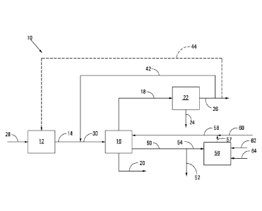
With reference to Figure 1 of the drawings, reference numeral 10
generally indicates a process employing an embodiment of the method of the
invention.
The process 10 includes broadly a synthesis gas generation stage 12, a moving-
bed
Fischer-Tropsch synthesis reactor 16, a cooling stage 22 and a catalyst
reactivation
facility 56.
Carbonaceous or hydrocarbonaceous feed material 28 is fed to the synthesis
gas generation stage 12 which is operated to produce fresh synthesis gas 14
which
includes H2 and CO. The fresh synthesis gas 14 is fed to the moving-bed
Fischer-
Tropsch synthesis reactor 16 in which the H2 and CO are catalytically
converted in the
presence of a Fischer-Tropsch catalyst into Fischer Tropsch products. The
Fischer-
Tropsch products range from normally gaseous hydrocarbons to liquid and waxy
hydrocarbons, as well as water and oxygenates. The gaseous hydrocarbons
include
methane and C2 hydrocarbons, unreacted synthesis gas components such as H2 and
CO, as well as CO2.
The synthesis gas generation stage 12 may be any synthesis gas generation
stage, e.g. a coal gasification stage or a natural gas reforming stage,
producing a
synthesis gas which is suitable for Fischer-Tropsch synthesis. The synthesis
gas from
Date Recue/Date Received 2020-07-24
CA 02968237 2017-05-17
WO 2016/081956 PCT/ZA2015/050016
the synthesis gas generation stage 12 may be subjected to one or more gas
cleaning
steps (not shown), where known Fischer-Tropsch catalyst poisons (e.g. H2S,
COS, NH3,
etc.) or other components (e.g. CO2) are removed from the synthesis gas
upstream of
the moving-bed Fischer-Tropsch synthesis reactor 16. The operation of such a
5
synthesis gas generation stage 12 and the optional gas clean-up steps are well
known
to those skilled in the art and are thus not described in any detail.
Similarly, the
operation of such a moving-bed Fischer-Tropsch synthesis reactor 16 is well
known to
those skilled in the art and is thus not described in any detail.
10 The
Fischer-Tropsch liquid and waxy products are withdrawn as a liquid
product stream 20 from the moving-bed Fischer-Tropsch synthesis reactor 16.
The
gaseous products are withdrawn from the moving-bed Fisher-Tropsch synthesis
reactor
16 as a gaseous product stream 18. The gaseous product stream 18 from the
moving-
bed Fisher-Tropsch synthesis reactor 16 is cooled in the cooling stage 22 to
condense
15
water and other condensable components such as oxygenates therefrom, with the
condensed components being separated and withdrawn as a stream 24. Cooled tail
gas 26 containing methane and C2 hydrocarbons, unreacted synthesis gas
components
such as H2 and CO, as well as CO2 is withdrawn from the cooling stage 22.
A portion of the tail gas 26 produced by the moving-bed Fischer-Tropsch
synthesis reactor 16 and withdrawn from the cooling stage 22 is optionally
recycled
back to the moving-bed Fischer-Tropsch synthesis reactor 16, as recycle tail
gas as
indicated by a dotted flow line 42. A feed synthesis gas 30 entering the
moving-bed
Fischer-Tropsch synthesis reactor 16 is thus an admixture of recycled tail gas
42 and
fresh synthesis gas 14. Optionally, a portion of the Fischer-Tropsch tail gas
26 may be
recycled to the synthesis gas generation stage 12, as shown by a dotted flow
line 44.
In accordance with the method of the invention, a portion of Fischer-
Tropsch catalyst is withdrawn from the moving-bed Fischer-Tropsch synthesis
reactor
16 via flow a line 50. The Fisher-Tropsch catalyst so withdrawn is in the form
of a slurry
of Fisher-Tropsch catalyst (i.e. Fisher-Tropsch catalyst particles), Fischer-
Tropsch
products (hydrocarbons and water) and entrained synthesis gas. The withdrawn
catalyst slurry in the flow line 50 is divided into a first portion 52 which
is discarded and
a second portion 54 which is sent to a catalyst reactivation facility 56.
Typically the
CA 02968237 2017-05-17
WO 2016/081956 PCT/ZA2015/050016
16
discarded catalyst 52 is subjected to a number of process steps to remove
entrained
synthesis gas and to separate the Fischer-Tropsch catalyst particles from
Fischer-
Tropsch product (not shown).
The details of the operation of the catalyst reactivation facility 56 are well
known to those skilled in the art, e.g. as set out in US Patent No. 6,838,487
and US
Patent Application No. 2002/0183403, and thus the catalyst reactivation
facility 56 and
the catalyst reactivation processes employed by the catalyst reactivation
facility 56 are
not described in any detail.
In one embodiment of the invention, the portion of withdrawn Fischer-
Tropsch catalyst 54 that is fed to the catalyst reactivation facility 56 is
subjected to a
regeneration treatment by contacting the catalyst with a diluted air stream
62.
Thereafter the regenerated (and oxidised) catalyst is subjected to a reduction
step by
the introduction of a hydrogen-containing stream 64 into the catalyst
reactivation facility
56. The reactivated catalyst is then returned via flow lines 57 and 58 to the
moving-bed
Fischer-Tropsch synthesis reactor 16.
In an alternative embodiment, the portion of withdrawn Fischer-Tropsch
catalyst 54 that is fed to the catalyst reactivation facility 56 is instead
subjected to a
rejuvenation treatment by contacting the catalyst with the hydrogen-containing
stream
64 only, prior to the reactivated catalyst being returned via the flow lines
57 and 58 to
the moving-bed Fischer-Tropsch synthesis reactor 16. That is, in the
alternative
embodiment, there is no regeneration treatment and thus no use of the diluted
air
stream 62.
In accordance with the method of the invention, fresh Fischer-Tropsch
catalyst 60, in this embodiment corresponding in mass to the mass of discarded
Fischer-Tropsch catalyst in the catalyst slurry portion 52, is added to the
reactivated
catalyst 58 and the combined stream introduced into the moving-bed Fisher-
Tropsch
synthesis reactor 16.
The catalyst reactivation facility 56 is operated on a batch basis, i.e.
batches of Fischer-Tropsch catalyst (in the form of a slurry) are periodically
withdrawn
CA 02968237 2017-05-17
WO 2016/081956 PCT/ZA2015/050016
17
from the moving-bed Fischer-Tropsch synthesis reactor 16, a portion 54 is
reactivated
either by a regeneration treatment or a rejuvenation treatment and returned to
the
moving-bed Fischer-Tropsch synthesis reactor 16, and a portion 52 is
discarded.
However, the moving-bed Fisher-Tropsch synthesis reactor 16 is operated
uninterruptedly, irrespective of whether catalyst containing slurry is
withdrawn on a
continuous or batch basis for reactivation purposes.
Prior Art Example
For the purposes of illustration, a closed-loop case, such as would be
found in the methods of the prior art, is considered. In this case it is
assumed that a
Fischer-Tropsch catalyst can be withdrawn from a Fischer-Tropsch synthesis
reactor
and reactivated safely a maximum of four times and that a Fischer-Tropsch
slurry
reactor starts to experience significant operating problems when more than
about
2.5 wt% of its Fischer-Tropsch catalyst inventory has reached or exceeded this
limiting
number of reactivation cycles. If 5 wt% of the catalyst inventory of the
Fischer-Tropsch
synthesis reactor is removed and reactivated per cycle, then the fraction of
Fischer-
Tropsch catalyst inside the Fischer-Tropsch synthesis reactor that has not
been
subjected to any reactivation cycles decreases after each reactivation cycle
as indicated
in Figure 2. However, the fraction of catalyst inside the Fischer-Tropsch
synthesis
reactor that has been subjected to four or more reactivation cycles increases
with every
reactivation cycle, exceeding the limiting value of 2.5 wt% after 23
reactivation cycles.
At this point, more than 30 wt% of the Fischer-Tropsch catalyst inventory of
the Fischer-
Tropsch synthesis reactor has never been reactivated. Since there is no
convenient
method to separate useful catalyst from spent catalyst, the whole catalyst
inventory has
to be discarded and the reactor is restarted with fresh catalyst. This
requires
interruption of the operation of the Fischer-Tropsch synthesis reactor, and is
undesirable.
Example According to a Preferred Embodiment of the Invention
In a second case, operation of a moving-bed Fisher-Tropsch synthesis
reactor employing a preferred embodiment of the method of the present
invention is
considered, i.e. where a portion of the withdrawn Fischer-Tropsch catalyst is
discarded
CA 02968237 2017-05-17
WO 2016/081956 PCT/ZA2015/050016
18
and a portion is reactivated and returned to the Fischer-Tropsch synthesis
reactor.
Discarding of a portion of the withdrawn Fischer-Tropsch catalyst according to
the
method of the invention is necessary in order to prevent the problem of spent
catalyst,
and in particular spent catalyst subjected to four or more reactivation
cycles, building up
in the Fisher-Tropsch reactor, as exemplified in Example 1.
Figure 3 shows the percentage of withdrawn Fischer-Tropsch catalyst that
has to be discarded (and made up with fresh Fischer-Tropsch catalyst) as a
function of
the numbers of reactivation cycles that a catalyst can tolerate. In Example 1,
the
catalyst was assumed to be able to tolerate up to a maximum of four
reactivation cycles.
At four reactivation cycles, approximately 37.5 wt% of each batch of the
withdrawn
Fischer-Tropsch catalyst is required to be discarded, with only the remaining
portion of
each batch (62.5 wt%) being subjected to the reactivation process before being
returned to the Fischer Tropsch synthesis reactor.
The method of the present invention, as illustrated, holds a number of
advantages over the methods described in the art. Firstly, the Fischer-Tropsch
reactor
can be run for an indefinite period without ever exceeding a limiting amount
of spent
catalyst inside the Fischer-Tropsch reactor, as would be the case for the
closed-loop
method of Example 1. This mitigates the need for shutting down or interrupting
Fisher-
Tropsch synthesis periodically due to a build-up of spent catalyst, enabling
much longer
production campaigns. Secondly, the average activity of the Fischer-Tropsch
catalyst
inventory inside the Fischer-Tropsch reactor remains substantially constant,
meaning
that the Fischer-Tropsch process can be run at or very close to its optimum
operating
conditions for substantially a full production campaign.
Notwithstanding that the method of the present invention requires the
discarding of
potentially significant amounts of Fischer-Tropsch catalyst that is fit for
continued use in
the Fischer-Tropsch synthesis process as is shown in Figure 3, it has
surprisingly been
found that the method of the present invention has a net economic benefit over
other
known approaches due to the foregoing advantages, at least in some cases.