Note: Descriptions are shown in the official language in which they were submitted.
CA 02968245 2017-05-17
84007129
SYSTEM AND METHOD FOR ENHANCED METAL RECOVERY DURING
ATMOSPHERIC LEACHING OF METAL SULFIDES
CROSS-REFERENCE TO RELATED APPLICATIONS
This application claims priority to and the benefit of co-pending United
States Provisional
Patent Application No. 62/082,293 filed on 20 November 2014 and titled "SYSTEM
AND
METHOD FOR ENHANCED METAL RECOVERY DURING ATMOSPHERIC
LEACHING OF METAL SULFIDES." This application also relates to International
Patent
Application No. PCT/US2015/050045 filed on 14 September 2014 and titled
"SYSTEM AND
METHOD FOR ENHANCED METAL RECOVERY DURING ATMOSPHERIC
LEACHING OF METAL SULFIDES."
FIELD OF THE INVENTION
Embodiments of the invention relate to equipment, flowsheets, and processes
for
improving metal value extraction from metal sulfide ores. In particular,
systems and methods
for increasing metal recovery within an atmospheric or substantially
atmospheric oxidative
leach circuit are disclosed.
1
CA 02968245 2017-05-17
WO 2016/081799 PCMJS2015/061761
BACKGROUND OF THE INVENTION
Current and past methods of atmospheric leaching of primary metal sulfides
(e.g.,
Chalcopyrite. Tennantite, and Enargite), may suffer from slow reaction
kinetics and poor metal
recoveries due to physical passivation effects during oxidative leaching.
Physical passivation
occurs when the growth of an elemental sulfur product layer occludes the
surfaces of the
particles being leached. The sulfur reaction product layer acts as a physical
barrier, impeding the
transport of reactants and products from the reaction plane.
A number of factors may enhance the detrimental effects of the sulfur product,
with
regard to metal dissolution, by altering the porosity and/or tortuosity of the
product layer. These
factors, individually or collectively, include crystal phase transformations,
partial melting and
recrystallization, or complete crystal melting. The range of passivation
effects will depend upon
the temperature of the reaction medium and the temperature at the reaction
zone which may be
different from the overall system temperature. This temperature difference may
be sustained
throughout the entire leach process, or it may be transitory.
Other mechanisms of passivation can include the formation of non-
stoichiometric, metal-
deficient sulfide phases that are resistant toward further anodic dissolution
reactions.
Furthermore, if the dissolution of the metal sulfide is taking place via an
electrochemical redox
mechanism, the anodic dissolution step will be dependent upon the pH and redox
potential at the
reaction plane.
A number of factors, known to those skilled in the art, can make it difficult
to maintain an
optimum redox potential and thereby achieve complete metal recovery at maximum
dissolution
rates. In some instances, leaching of primary metal sulfides from ore
concentrates may also
2
CA 02968245 2017-05-17
WO 2016/081799 PCT/US2015/061761
suffer from slow reaction kinetics and poor metal recoveries due to residual
frothing agents used
during froth flotation. The residual frothing agents may be present on
particles being leached
and interfere with superficial leaching chemistries.
A number of past methods have been attempted to increase metal leach rates by
employing leach catalysts. One approach suggested addressing the passivation
issue by
increasing electron transport though an electrically-resistive, reaction-
product layer by doping
the layer with fine particulate carbon (see for example US-4,343,773).
Moreover, a more
recently-proposed method (US-2012/0279357) for addressing passivation relies
on the addition
of an activated carbon catalyst to enhance the leach rate of arsenic-
containing copper sulfides.
Still other approaches have used silver-based catalytic leach systems for
enhancing the copper
dissolution rates in acidic ferric sulfate media (J. D. Miller, P. J.
McDonough and P. J. Portillo,
Electrochemistry in Silver Catalyzed Ferric Sulfate Leaching of Chalcopyrite,
in Process and
Fundamental Considerations of Selected Hydrometallurgical Systems, M. C. Kuhn,
Ed., SME-
AIME, New York, pp. 327-338, 1981), while others have used silver-activated
pyrite to
accomplish similar results (US-8,795,612). The Applicant has further recently
proposed a
method and process for the enhanced leaching of copper-bearing sulfide
minerals which utilizes
microwave irradiation during leaching to combat the adverse effects of
passivation on leaching
(W02014074985A1).
Still others have adopted pre-leach, ultra-fine grinding (i.e., purely
mechanical pre-leach
activation via particle size reduction) of a copper sulfide concentrate to
achieve rapid post-
grinding leach kinetics (US 5,650,057). US-5,993,635 describes a method for
recovering copper
from sulfide-mineral compositions which comprises the step of ultra-fine
grinding of the leach
feed to a P80 of about 3-51.1m (see Example 3 in US-5,993,635). While copper
dissolutions of
3
CA 02968245 2017-05-17
WO 2016/081799 PCT/US2015/061761
95% or greater were achieved in 10 hours on a small scale, grinding to such a
small particle size
prior to leaching becomes progressively less economical in mid- to low-grade
metal
concentrates.
A few prior methods have combined ultra-fine grinding and leaching in so-
called batch
Mechano-Chemical leaching processes; however, these leaching processes are
high-energy
circular "batch" processes which do not provide for continuous downstream flow
or plug flow.
Moreover, all prior art methods have, to date, required excessively large
energy inputs to achieve
significant levels of copper dissolution from chalcopyrite. While leach times
to achieve 80%
copper extraction have been demonstrated to be as short as 1 hour, the
approach is difficult to
adapt for large-scale commercial operation (D. A. Rice, J. R. Cobble, and D.
R. Brooks. Effects
of Turbo-milling Parameters on the Simultaneous Grinding and Ferric Sulfate
Leaching of
Chalcopyrite. RI 9351, US Bureau of Mines, 1991). Furthermore, copper
recoveries in excess of
95-97 % were not achievable due to passivation at high elemental sulfur
loading, which the
inventors have interpreted as indicating a plurality of mechanisms are
actively impeding metal
dissolution and recovery.
Furthermore, while mechano-chemical processes can accelerate reaction rates by
taking
advantage of the immediate reactivity of free radicals generated at the moment
of bond breakage,
prior art methods have not been known, nor anticipated, to be operative at the
atomic level and in
reactions not involving the making or breaking of chemical bonds (e.g.,
acceleration of the
oxidation of ferrous to ferric).
Even with pretreatment by ultra-fine grinding, surface passivation reactions
continue to
be problematic. Efforts to reduce leach times to under 9 hours in which the
concentrates are
4
84007129
pretreated prior to leaching, by ultra-fine grinding of metal sulfides, have
been largely
unsuccessful. Improved methods are needed to economically reduce leach times
and
increase metal dissolution and recoveries to 98% and above.
OBJECTS OF THE INVENTION
It is preferred that embodiments reduce and/or eliminate the need for the
addition
of a superfluous reagent or reagents into a leach circuit, to mitigate
additional costs
associated with purchasing, shipping, and dosing.
Moreover, it is preferred that embodiments reduce and/or eliminate the need
for the
addition of a superfluous reagent or reagents into a leach circuit, to
mitigate negative
impacts to downstream SX/EW systems.
It is further desired to mitigate the effects of physical and/or
electrochemical
passivation by employing novel Mechano-Chemical/Physico-Chemical techniques in
a
continuous oxidative leach circuit of a continuous metal recovery flowsheet.
These and other objects of the present invention will be apparent from the
drawings
and description herein. Although every object of the invention is believed to
be attained by
at least one embodiment of the invention, there is not necessarily any one
embodiment of
the invention that achieves all of the objects of the invention.
BRIEF DESCRIPTION OF THE DRAWINGS
To complement the description which is being made, and for the purpose of
aiding
to better understand the features of the invention, a set of drawings
illustrating preferred
apparatus and methods of using the same is attached to the present
specification as an
integral part thereof, in which the following has been depicted with an
illustrative and non-
limiting character. It should be understood that like reference numbers used
in the
drawings (if any are used) may identify like components.
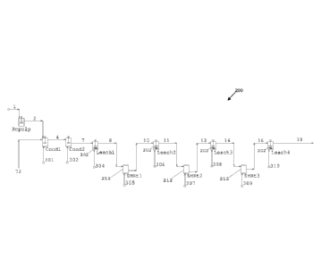
FIG. 1 is a schematic diagram illustrating a non-limiting, exemplary
continuous
oxidative leach circuit portion of a metal recovery flowsheet which might
employ certain
aspects of the invention, wherein novel shear-tank reactors may be disposed
between
Date recue / Date received 2021-12-17
84007129
stirred-tank reactors, in series; in other words, a shear-tank reactor within
an oxidative
leach circuit may receive leach slurry from an upstream stirred-tank reactor
and/or feed a
downstream stirred-tank reactor. The oxidative leach circuit may, as shown,
comprise at
least one pre-conditioning tank.
FIG. 2 is a schematic diagram illustrating a non-limiting, exemplary
continuous
oxidative leach circuit portion of a metal recovery flowsheet which might
employ certain
aspects of the invention, wherein novel shear-tank reactors may be disposed in
parallel; in
other words, a shear-tank reactor within an oxidative leach circuit may
receive leach slurry
from a respective stirred-tank reactor and may re-feed the same respective
stirred-tank
reactor. The oxidative leach circuit may, as shown, comprise at least one pre-
conditioning
tank.
FIG. 3 is a schematic diagram illustrating a non-limiting, exemplary
continuous
oxidative leach circuit portion of a metal recovery flowsheet which might
employ certain
aspects of the invention. As shown, the oxidative leach circuit may comprise a
solid-liquid
separation step, preferably mid-process, to help prevent copper concentration
buildup.
FIG. 4 is a schematic diagram illustrating a non-limiting, exemplary
continuous
oxidative leach circuit portion of a metal recovery flowsheet which might
employ certain
aspects of the invention. As shown, the oxidative leach circuit may comprise a
number of
larger stirred-tank reactors within a first portion of an oxidative leach
circuit, followed by
a solid-liquid separation step to help prevent copper concentration buildup;
wherein
downstream of solid-liquid separation apparatus, a number of smaller stirred-
tank reactors
interposed between a number of shear-tank reactors is employed.
FIG. 5 is a schematic diagram illustrating a non-limiting, exemplary
continuous
oxidative leach circuit portion of a metal recovery flowsheet which might
employ certain
aspects of the invention. As shown, the oxidative leach circuit may comprise a
stirred-tank
reactor having at least one shear-tank reactor disposed therein, in-situ. A
number of the
hybrid devices may be operatively connected in series (as shown), and/or they
may be
arranged in a parallel configuration (not shown), without limitation.
FIG. 6 is a schematic diagram illustrating a non-limiting exemplary oxidative
leach
circuit which may be used to obtain batch leach test measurements.
5a
Date recue / Date received 2021-12-17
84007129
FIGS. 7-11 illustratively show results obtained via bench-scale testing using
the
oxidative leach circuit shown in FIG. 6.
FIG. 12 is a schematic diagram illustrating a non-limiting, exemplary metal
recovery flowsheet which might advantageously employ certain embodiments of
the novel
oxidative leach circuits disclosed herein.
FIG. 13 is a schematic diagram illustrating, in more detail, a portion of the
non-
limiting, exemplary metal recovery flowsheet shown in FIG. 12.
FIG. 14 schematically depicts mechano-chemical processing which may occur in a
shear-tank reactor according to some embodiments.
FIG. 15 schematically depicts physico-chemical processing which may occur in a
shear-tank reactor according to some embodiments.
In the following, the invention will be described in more detail with
reference to
drawings in conjunction with exemplary embodiments.
5b
Date recue / Date received 2021-12-17
CA 02968245 2017-05-17
WO 2016/081799 PCT/US2015/061761
SUMMARY OF THE INVENTION
An oxidative leach circuit is disclosed. The oxidative leach circuit may
comprise at least
one stirred-tank reactor and at least one shear-tank reactor configured to
impart a higher shear to
particles than the at least one stirred-tank reactor. In some embodiments, the
at least one shear-
tank reactor operates at a higher power density than the at least one stirred-
tank reactor. The at
least one stirred-tank reactor and the at least one shear-tank reactor may be
connected in series,
for example, in an inter-stage configuration. The at least one stirred-tank
reactor and the at least
one shear-tank reactor may be connected in parallel, for example, in an intra-
stage configuration.
The at least one shear-tank reactor may be disposed within the at least one
stirred-tank reactor,
for example, in an in-situ configuration. The oxidative leach circuit may, in
some embodiments,
comprise at least two stirred-tank reactors. The oxidative leach circuit may,
in some
embodiments, comprise at least two shear-tank reactors. The at least one shear-
tank reactor may
provide a mechano-chemical or physico-chemical reaction and the at least one
stirred-tank
reactor may provide a chemical reaction during operation. The at least one
shear-tank reactor
may, in some embodiments, comprise a stirred media reactor, a high-shear
reactor comprising
one or more high-shear impellers, or a high-shear reactor comprising a high
shear rotor and a
high shear stator. The at least one shear-tank reactor may comprise a stirred
media reactor which
comprises grinding media. The at least one shear-tank reactor may comprise one
or more high-
shear impellers. The at least one shear-tank reactor may comprise one or more
pumping blades.
Each shear-tank reactor may comprise at least one high shear rotor and at
least one high shear
stator.
6
CA 02968245 2017-05-17
WO 2016/081799 PCT/US2015/061761
A method of improving leach kinetics and metal recovery during atmospheric or
substantially atmospheric leaching of a metal sulfide is further disclosed.
According to some
embodiments, the method may comprise the steps of: (a) producing a metal
sulfide concentrate
via flotation; (b) processing the metal sulfide concentrate in one or more
stirred-tank reactors to
produce an oxidatively-processed metal sulfide concentrate; and, (c) physico-
chemically
processing particles within the metal sulfide concentrate or within the
oxidatively-processed
metal sulfide concentrate in one or more shear-tank reactors; wherein the one
or more shear-tank
reactors are configured to impart a greater amount of shear on the particles
than the one or more
stirred-tank reactors. The method may further comprise the step of (d)
extracting metal from the
particles, the metal comprising iron, nickel, cobalt, copper, zinc, silver,
gold, antimony, or
bismuth. The method may further comprise the step of (e) extracting a non-
metal from the
particles, the non-metal comprising arsenic or sulfur. Step (c) may be
performed in series with
step (b), or step (c) may be performed in parallel with step (b), without
limitation. Step (c) may,
in some instances, be performed before or after step (b). In some embodiments,
step (c) and step
(b) may be performed in a hybrid configuration wherein at least one of the one
or more shear-
tank reactors are provided within at least one of the one or more stirred-tank
reactors. The one or
more shear-tank reactors may comprise a stirred media reactor, a high-shear
stirred reactor
comprising one or more high-shear impellers, or a high-shear reactor
comprising a high shear
rotor and high shear stator, without limitation. In some instances, the one or
more shear-tank
reactors may comprise grinding media. In some instances, the one or more shear-
tank reactors
may comprise at least one high shear impeller. In some instances, the one or
more shear-tank
reactors may comprise at least one pumping blade. In some instances, the one
or more shear-
tank reactors may comprise at least one high shear rotor and at least one high
shear stator.
7
CA 02968245 2017-05-17
WO 2016/081799 PCT/US2015/061761
An oxidative leach circuit 200 for improving leach kinetics and metal recovery
during
atmospheric or substantially atmospheric leaching of a metal sulfide is
further disclosed, the
oxidative leach circuit 200 comprising: (a) at least one stirred tank leach
reactor; and (b) at least
one shear-tank reactor configured to impart a greater amount of shear to
particles of a metal
sulfide than the at least one stirred tank reactor. The oxidative leach
circuit may comprise at
least two stirred tank reactors and (c) a solid-liquid separation device
disposed between the at
least two stirred tank reactors. The stirred tank reactor downstream of the
solid-liquid separation
device may be volumetrically smaller than the stirred tank leach reactor
upstream of the solid-
liquid separation device. In some embodiments, the oxidative leach circuit may
further comprise
(c) a solid-liquid separation device disposed between the at least one shear-
tank reactor and the
at least one stirred tank reactor. The at least one shear-tank reactor may be
disposed within said
at least one oxidative stirred tank leach reactor. The at least one shear-tank
reactor may be
disposed between two stirred tank reactors. The at least one shear-tank
reactor may be arranged
in an intra- stage configuration with the at least one stirred tank reactor;
wherein the at least one
shear-tank reactor may be fed by the at least one stirred tank reactor, and
wherein the at least one
shear-tank reactor may re-feed the at least one stirred tank reactor. The at
least one shear-tank
reactor may be selected from a stirred media reactor, a high-shear stirred
reactor comprising one
or more high-shear impellers and/or pumping blades, or a high-shear reactor
comprising a high
shear rotor and stator. The at least one shear-tank reactor may comprise
grinding media. The at
least one shear-tank reactor may comprise one or more high shear impellers
selected from the
following list: a gate blade, a pitched blade, a bow blade, a coil blade, a
curved radial blade, a
sweep blade, a dis-mounted blade, a dual hi-speed blades, an alternating tooth
blade. non-
alternating tooth blade, a high-vane blade, a Cowles blade, and a pick blade.
The at least one
8
CA 02968245 2017-05-17
WO 2016/081799 PCT/US2015/061761
shear-tank reactor may comprise at least one high shear rotor and at least one
high shear stator.
The at least one stirred tank reactor may operate at a first grinding energy
and the at least one
shear-tank reactor may operate at a second grinding energy which is higher
than the first
grinding energy. The at least one stirred tank reactor may operate at a first
power density and the
at least one shear-tank reactor may operate at a second power density which is
higher than the
first grinding energy.
In some embodiments, an oxidative leach circuit may comprise a first stirred-
tank
reactor; a second stirred-tank reactor; and a shear reactor disposed between
the first stirred-tank
reactor and the second stirred-tank reactor. In some embodiments, an oxidative
leach circuit may
comprise a first shear-tank reactor; a second shear-tank reactor; and a
stirred-tank reactor
disposed between the first shear-tank reactor and the second shear-tank
reactor.
In some embodiments, an oxidative leach circuit may comprise a first stirred-
tank
reactor; and a shear- reactor or shear-tank reactor disposed within the first
stirred-tank reactor.
In some embodiments, an oxidative leach circuit may comprise: (a) a first
stirred-tank reactor
having a first inlet configured to receive a metal sulfide concentrate; a
first outlet configured to
convey the metal sulfide concentrate downstream to another stirred-tank
reactor; a first intra-
stage outlet configured to convey the metal sulfide concentrate to a shear-
tank reactor; and a first
intra- stage inlet configured to receive the metal sulfide concentrate from
the shear-tank reactor;
and (b) a shear-tank reactor having a first intra-stage inlet configured to
receive the metal sulfide
concentrate from the first stiffed-tank reactor; and a first intra-stage
outlet configured to convey
the metal sulfide concentrate to the first stirred-tank reactor.
In some embodiments, an oxidative leach circuit may comprise: (a) a first
stirred-tank
reactor having: an inlet configured to receive a metal sulfide concentrate;
and an outlet
9
CA 02968245 2017-05-17
WO 2016/081799 PCT/US2015/061761
configured to convey the metal sulfide concentrate from the first stirred-tank
reactor; (b) a
second stirred-tank reactor having an inlet and being provided downstream of
the first stirred-
tank reactor; (c) a solid-liquid separation device provided between the first
stirred-tank reactor
and the second stirred-tank reactor, the solid-liquid separation device
operatively communicating
with the outlet of the first stirred-tank reactor and the inlet of the second
stirred-tank reactor,
wherein the solid-liquid separation device is configured to dewater the metal
sulfide concentrate
received from the first stirred-tank reactor and pass the liquid fraction to
the inlet of the second
stirred-tank reactor; and (d) at least one shear-tank reactor configured to
impart higher shear to
particles within the metal sulfide concentrate than either the first stirred-
tank reactor or the
second stirred-tank reactor. The second stirred-tank reactor may have a
smaller volumetric ratio
than the first stirred-tank reactor. The first stirred-tank reactor or the
second stirred-tank reactor
may be connected in series to the at least one shear-tank reactor. The first
stirred-tank reactor or
the second stirred-tank reactor may be connected in parallel to the at least
one shear-tank reactor.
The at least one shear-tank reactor may be disposed within the first stirred-
tank reactor or the
second stirred-tank reactor. The at least one shear-tank reactor disposed
within the first stirred-
tank reactor or the second stirred-tank reactor may comprise a shear reactor
which does not
comprise a tank or tank portions.
In some embodiments, an oxidative leach circuit may comprise: at least one
stirred-tank
reactor; and at least one shear-tank reactor comprising reacting particles;
wherein the at least one
shear-tank reactor is configured with mechanical means for either: i.)
synergistically disrupting
particle-particle agglomerations resulting from a production of a hydrophobic
elemental sulfur
reaction product at the surfaces of the reacting particles, or ii.)
synergistically re-arranging
CA 02968245 2017-05-17
WO 2016/081799 PCT/US2015/061761
particle-particle agglomerations resulting from a production of a hydrophobic
elemental sulfur
reaction product at the surfaces of the reacting particles. In some
embodiments. disrupting
particle-particle agglomerations comprises breaking particle-particle contacts
within a particle-
particle agglomeration. In some embodiments, step i) or ii) may alter a
diffusion path length to
and from a reaction plane. In some embodiments, step i) or ii) may accelerate
mass transfer to
and from a reaction plane.
In some embodiments, an oxidative leach circuit may comprise at least one
stirred-tank
reactor; at least one shear-tank reactor; and, a solid/solid separation
apparatus downstream of the
at least one stirred-tank reactor and the at least one shear-tank reactor;
wherein the solid/solid
separation apparatus may be configured for separating elemental sulfur
reaction products from
other particles within the oxidative leach circuit. In some embodiments, the
oxidative leach
circuit may further comprise a recycle stream operatively connected to the
solid/solid separation
apparatus, wherein the recycle stream is configured for recycling particles
within the oxidative
leach circuit which have been separated from elemental sulfur via the
solid/solid separation
apparatus, and bringing recycled particles to any one or more of the
following: a re-grind circuit
located upstream of the oxidative leach circuit, the at least one stirred-tank
reactor, the at least
one shear-tank reactor, or a conditioning tank, without limitation.
A method of leaching is further disclosed. According to some embodiments, the
method
comprises the steps of: (a) providing an oxidative leach circuit 200
comprising at least one
stirred-tank reactor 202 and at least one shear-tank reactor 212; (b)
processing a flotation
concentrate comprising metal sulfide particles within the at least one stirred-
tank reactor 202 and
the at least one shear-tank reactor 212; (c) forming agglomerations containing
said metal sulfide
11
CA 02968245 2017-05-17
WO 2016/081799 PCT/US2015/061761
particles within the at least one stirred-tank reactor 202; and (d)
intermittently disrupting the
agglomerations within the at least one shear-tank reactor 212 to enhance leach
kinetics of the
metal sulfide particles, increase metal recovery from the metal sulfide
particles, or reduce the
effective electrochemical diffusion path lengths within the agglomerations.
Step (c) may
comprise actively forming agglomerations using a flocculant, rather than
passively forming
agglomerations.
A method of extracting sulfur from a metal sulfide concentrate is further
disclosed.
According to some embodiments, the method comprises (a) mechano-chemically
and/or physico-
chemically processing the particles; (b) separating elemental sulfur from the
mechano-
chemically and/or physico-chemically processed particles of step (a) using a
solid-solid
separation apparatus; and (c) removing the elemental sulfur separated in step
(b) from the solid-
solid separation apparatus. The solid-solid separation apparatus may be
configured for
particle/particle separation based on density of the mechano-chemically and/or
physico-
chemically processed particles. The solid-solid separation apparatus may
comprise a centrifugal
device, such as a gravity centrifugal concentrator (e.g., a batch or
continuous variable discharge)
or cyclone, without limitation.
A continuous oxidative leach circuit within a metal recovery flowsheet is
disclosed. In
some embodiments, the oxidative leach circuit may be maintained at a redox
potential between
600 mV (SHE) and 800 mV (SHE), for example, between 650 mV (SHE) and 750 mV
(SHE).
In some embodiments, the oxidative leach circuit is configured for oxidatively
leaching a metal
sulfide concentrate and may comprise a combination of: a plurality of stirred-
tank reactors, and
one or more shear-tank reactors. In some embodiments, the stirred-tank
reactors may be
12
CA 02968245 2017-05-17
WO 2016/081799 PCT/US2015/061761
oxidative leach reactors and may be arranged in series with the shear-tank
reactor(s). In some
embodiments, the stirred-tank reactors may be arranged in parallel with the
shear-tank reactor(s).
In some embodiments, the stirred-tank reactors may be arranged both in series
and in parallel
with shear-tank reactors. In some embodiments. a shear-tank reactor may be
disposed within a
stirred-tank reactor, in-situ. In some embodiments, a single shear-tank
reactor may be shared
between multiple, stirred-tank reactors. It is anticipated that various
permutations/combinations
of the aforementioned configurations may be employed, without limitation.
A metal recovery flowsheet comprising a continuous oxidative leach circuit is
also
disclosed. The metal recovery flowsheet may comprise: (a) a sulfide
concentrator comprising a
flotation circuit to produce a metal sulfide concentrate; and (b) an
atmospheric or substantially
atmospheric metal sulfide leach circuit. The atmospheric or substantially
atmospheric metal
sulfide leach circuit may comprise an oxidative leach circuit for recovering
at least one metal
value from the metal sulfide concentrate via dissolution. Various non-limiting
embodiments of
exemplary oxidative leach circuits can be seen in FIGS. 1-5.
In some embodiments, the oxidative leach circuit may be maintained at a pH
below about
1.0 and a redox potential between 600 mV (SHE) and 800 mV (SHE). In some
embodiments,
the oxidative leach circuit may comprise one or more shear-tank reactors
operatively connected
to a plurality of stirred-tank reactors. One, some, or all of the stirred-tank
reactors may comprise
a redox-control source, such as one or more oxygen and/or enriched air
spargers. One, some, or
all of the shear-tank reactors may comprise a redox-control source, such as
one or more oxygen
and/or enriched air spargers.
13
CA 02968245 2017-05-17
WO 2016/081799 PCT/US2015/061761
According to some embodiments, oxidative dissolution may occur in a stirred-
tank
reactor at a redox potential between about 600 to about 800 mV (SHE), a range
traditionally
known to promote passivation, slowdown, or complete shutdown of leach
kinetics.
According to some embodiments, the metal sulfide concentrate comprises
chalcopyrite.
According to some embodiments, oxidative dissolution is carried out in a shear-
tank reactor;
wherein the shear-tank reactor may be selected from at least one of the group
consisting of: a
stirred media reactor, a high-shear stirred reactor comprising one or more
high-shear impellers
and/or pumping blades, and a high-shear reactor comprising at least one high
shear rotor and at
least one high shear stator.
According to some embodiments, the oxidative leach circuit may be configured
for
leaching greater than 80% metal in under about 9 hours (e.g., under about 6
hours) by providing
and operating a shear-tank reactor at a power density ranging from about 2
kilowatts per cubic
meter to about 100 kilowatts per cubic meter. According to some embodiments,
the oxidative
leach circuit may be configured for leaching greater than 95% metal in under
about 9 hours (e.g.,
under about 6 hours) by providing and operating a shear-tank reactor at a
power density ranging
from about 5 kilowatts per cubic meter to about 100 kilowatts per cubic meter.
According to some embodiments, the oxidative leach circuit may be configured
for
leaching greater than 98% metal in under about 9 hours (e.g., under about 6
hours) by providing
and operating a shear-tank reactor at a power density ranging from about 5
kilowatts per cubic
meter to about 20 or 30 kilowatts per cubic meter. According to some
embodiments, the
oxidative leach circuit may be configured for leaching greater than 95% metal
in under about 9
14
CA 02968245 2017-05-17
WO 2016/081799 PCT/US2015/061761
hours (e.g., under about 6 hours) by providing and operating a shear-tank
reactor at a power
density ranging from about 20 kilowatts per cubic meter to about 100 kilowatts
per cubic meter.
In some preferable embodiments, the metal leached from the metal sulfide
comprises copper. .
In still other embodiments, the metal leached from the metal sulfide comprises
zinc.
According to some preferred embodiments, oxidative leaching of metal sulfide
particles
may be enhanced by a physico-chemical process made possible by an oxidative
leach circuit
having physico-chemical processing means. The physico-chemical processing
means may
substantially reduce both the electrochemical passivation and physical
passivation of a metal
sulfide particle via a physico-chemical mechanism. According to some
embodiments, the
physico-chemical mechanism may comprise a physical/mechanical shearing process
component,
for example, at least one shear-tank reactor, and a chemical leaching process
component, for
example, at least one stirred-tank reactor within the same oxidative leach
circuit. According to
some embodiments, the shearing process component may be configured to
synergistically impart
mechanical scrubbing, grinding, attrition, or a combination thereof to metal
sulfide particles.
According to another embodiment of the invention, the shearing process
component may be
configured to synergistically impart physical disruption of particle-particle
agglomeration
resulting from the production of a hydrophobic elemental sulfur reaction
product at the surfaces
of the reacting metal sulfide particles during oxidative leaching. It should
be understood that
chemical interactions may occur within the shearing process component and that
these chemical
interactions may differ from those found within conventional stirred-tank
reactors and/or the
chemical leaching process component.
CA 02968245 2017-05-17
WO 2016/081799 PCT/US2015/061761
According to some embodiments, the shearing process component may comprise a
shear-
tank reactor, for example, a reactor which is selected from at least one of
the group consisting of:
a stirred media reactor, a high-shear reactor, a stirred reactor comprising
one or more high-shear
impellers (e.g., a Cowles blade) and/or pumping blades, and a reactor
comprising at least one
high-shear rotor and at least one high-shear stator. According to some
embodiments, the
shearing process component may be situated downstream of the chemical leaching
component.
According to some embodiments, the shearing process component may be situated
upstream of
the chemical leaching component. According to some embodiments, the shearing
process
component may be situated within the chemical leaching component, or vice-
versa so as to
provide both components of the physico-chemical mechanism within the same
device.
According to some embodiments, the shearing process component may be situated
in series, in
parallel, and/or within the chemical leaching component in the same oxidative
leach circuit.
According to some embodiments, the chemical leaching component and the
shearing process
component may form portions of a continuous flow-through linear oxidative
leach circuit 200,
rather than portions of a circular or batch oxidative leach circuit.
According to some embodiments, one or more stirred-tank reactors may be
operated
under atmospheric pressure and one or more shear-tank reactors may be operated
above
atmospheric pressure or at atmospheric pressure. According to some preferred
embodiments, a
shear tank reactor may be configured to operate at less than 20 bar and at or
greater than 1 bar.
For example, shear-tank reactors disclosed herein may be configured to be
operated at an oxygen
overpressure pressure ranging from about 1 to about 10 bar. Even more
preferably, shear-tank
reactors disclosed herein may be configured to be operated at an oxygen
overpressure ranging
16
CA 02968245 2017-05-17
WO 2016/081799 PCT/US2015/061761
from about 1 to about 5 bar, without limitation. According to some
embodiments, metal sulfide
particles may spend greater than about 80-95% of their total collective
residence time within the
stirred-tank reactors¨ for example, preferably under atmospheric or
substantially atmospheric
conditions. According to some embodiments, metal sulfide particles may spend
less than about
10-20% of their total collective residence time within the shear-tank
reactors¨ for example, under
substantially atmospheric conditions or above atmospheric conditions.
According to some
embodiments, a shearing process occurring within a respective shear-tank
reactor may comprise
controlling both the pH and redox potential simultaneously by using acid,
ferric iron, gaseous 02,
air, or a combination thereof.
Turning now to the figures, one or more shear-tank reactors 212 may be
employed (also
labeled in the drawings as "SMRt") within an oxidative leach circuit 200. In
some embodiments,
as shown in FIG. 1, the one or more shear-tank reactors 212 may be arranged in
series (i.e.,
"inter-stage") between respective adjacent stirred-tank reactors 202 (also
labeled in the drawings
as "LEACH"). The stirred-tank reactors 202 are preferably utilized as
oxidative leach reactors
and may comprise conventional stirred tank reactors (CSTRs), without
limitation. In some
embodiments, the one or more shear-tank reactors 212 may be arranged in
parallel (i.e., "intra-
stage") so as to receive feed from and operatively re-feed the same stirred-
tank reactor 202, as
shown in FIG. 2. In some embodiments, a solid-liquid separation or dewatering
step comprising
one or more pieces of solid-liquid separation or dewatering equipment may be
provided in the
leach circuit 200, as shown in the center of FIG. 3, to address excessive
concentration buildup
within the system. For example, the solid-liquid separation or dewatering
equipment may be
employed to prevent copper concentrations that exceed solubility limits or
prevent copper
17
CA 02968245 2017-05-17
WO 2016/081799 PCT/US2015/061761
concentrations that exceed the capabilities of a solvent extraction and
electrowinning (SX/EW)
system (not shown) located downstream of the oxidative leach circuit 200. In
some
embodiments, stirred-tank reactors 202 may successively increase in their
effective residence
time and/or size (e.g., volume) as the metal recovery flowsheet progresses
downstream. In this
regard, the risk of pregnant leach solution (PLS) becoming too concentrated in
copper and iron
may be mitigated.
According to some embodiments a wetting agent may be used to control frothing.
The
wetting agent may comprise a polymeric electrolyte, a polymeric flocculant, or
a variety of
polymeric electrolytes and polymeric flocculants can be used alone or in
combination, without
limitation. According to some embodiments, a wetting agent may be
advantageously used to
reduce the amount of residual metal in leach tailings from the oxidative leach
circuit 200 to less
than 1 wt. %, more advantageously to less than 0.8 wt. % and more
advantageously to less than
0.5 wt. %. Preferably, the amount of residual metal in the leach tailings from
the oxidative leach
circuits disclosed herein is around, equal to, or less than run-of-mine (ROM)
material.
According to some embodiments, one or more shear-tank reactors 212 may be
operatively coupled to a plurality of stirred-tank reactors 202, wherein a
collective residence time
of the metal sulfide particles in the one or more shear-tank reactors 212
depends upon or is a
function of overall residence time within the entire oxidative leach circuit
200. The residence
time within the one or more shear-tank reactors 212 may also depend upon or be
a function of a
volumetric ratio between the total combined volume of the stirred-tank
reactor(s) 202 within the
oxidative leach circuit 200, and the total combined volume of the shear-tank
reactor(s) 212
within the oxidative leach circuit 200. The preferred volumetric ratio is not
equal to one.
18
CA 02968245 2017-05-17
WO 2016/081799 PCT/US2015/061761
According to some embodiments, the volumetric ratio of the shear-tank
reactor(s) 212 to the
stirred-tank reactor(s) 202 may be between about 1:2 and about 1:200; for
example, between
about 1:4 and about 1:175; or between about 1:10 and about 1:150; or between
about 1:20 and
about 1:100; or between about 1:25 and about 1:75; or between about 1:30 and
about 1:50, such
as approximately 1:40, without limitation.
According to some embodiments, about 90% or greater metal recovery may be
achieved
in less than 20 hours (e.g., less than 10 hours) while operating portions of
the oxidative leach
circuit 200 at a temperature below the melting point of elemental sulfur.
According to some
embodiments, about 90% or greater metal recovery may be achieved in less than
9 hours (e.g.,
less than 6 hours) while operating portions of the oxidative leach circuit 200
at a temperature
below the melting point of elemental sulfur. According to some embodiments,
about 95% or
greater metal recovery may be achieved in less than 10 hours while operating
portions of the
oxidative leach circuit 200 at a temperature below the melting point of
elemental sulfur.
According to some embodiments, about 95% or greater metal recovery may be
achieved in less
than 6 hours while operating portions of the oxidative leach circuit 200 at a
temperature below
the melting point of elemental sulfur.
According to some embodiments, the metal recovery flowsheet may further
comprise an
ultra-fine grinding mill (not shown for clarity) for ultra-fine grinding the
concentrate upstream of
the oxidative leach circuit 200 (i.e., prior to oxidative leaching). According
to some
embodiments, the ground concentrate may comprise a P95 of 100 microns or
finer. According to
some embodiments, the ground concentrate may comprise a P95 of 75 microns or
finer.
19
84007129
According to some embodiments, the ground concentrate may comprise a P95 of
40 microns or finer, prior to oxidative leaching.
According to some embodiments, the metal recovery flowsheet may further
comprise means for the addition of viscosity modifiers for increasing shear
experienced by
particles within the shear-tank reactors 212.
Certain embodiments of the invention include:
- an oxidative leach circuit comprising at least one stirred-tank reactor
and at least
one shear-tank reactor configured to impart a higher shear to particles than
the at least one
stirred-tank reactor; the at least one shear-tank reactor operating at a
higher power density
than the at least one stirred tank reactor; and the at least one shear-tank
reactor comprising
a stirred media reactor which comprises grinding media, wherein the at least
one stirred-
tank reactor and the at least one shear-tank reactor are connected in
parallel;
- an oxidative leach circuit comprising at least one stirred-tank reactor
and at least
one shear-tank reactor configured to impart a higher shear to particles than
the at least one
stirred-tank reactor; the at least one shear-tank reactor operating at a
higher power density
than the at least one stirred tank reactor; and the at least one shear-tank
reactor comprising
a stirred media reactor which comprises grinding media, wherein the at least
one shear-
tank reactor is disposed within the at least one stirred-tank reactor;
- an oxidative leach circuit for improving leach kinetics and metal
recovery during
atmospheric or substantially atmospheric leaching of a metal sulfide, the
oxidative leach
circuit comprising: (a) at least two stirred tank leach reactors; and (b) at
least one shear-
tank reactor configured to impart a greater amount of shear to particles of a
metal sulfide
than the at least two stirred tank reactors; wherein the at least one shear-
tank reactor
comprises grinding media; and wherein the at least two stirred tank reactors
operate at a
lower power density than the at least one shear-tank reactor, wherein a solid-
liquid
separation device is disposed between two of the at least two stirred tank
reactors;
- an oxidative leach circuit for improving leach kinetics and metal
recovery during
atmospheric or substantially atmospheric leaching of a metal sulfide, the
oxidative leach
circuit comprising: (a) at least one stirred tank leach reactor; and (b) at
least one shear-tank
reactor configured to impart a greater amount of shear to particles of a metal
sulfide than
Date recue / Date received 2021-12-17
84007129
the at least one stirred tank reactor; wherein the at least one shear-tank
reactor comprises
grinding media; and wherein the at least one stirred tank leach reactor
operates at a first
power density and the at least one shear-tank reactor operates at a second
power density
which is higher than the first power density; the oxidative leach circuit
further comprising
(c) a solid-liquid separation device disposed between the at least one shear-
tank reactor
and the at least one stirred tank reactor;
- an oxidative leach circuit for improving leach kinetics and metal
recovery during
atmospheric or substantially atmospheric leaching of a metal sulfide, the
oxidative leach
circuit comprising: (a) at least one stirred tank leach reactor; and (b) at
least one shear-tank
reactor configured to impart a greater amount of shear to particles of a metal
sulfide than
the at least one stirred tank reactor; wherein the at least one shear-tank
reactor comprises
grinding media; and wherein the at least one stirred tank leach reactor
operates at a first
power density and the at least one shear-tank reactor operates at a second
power density
which is higher than the first power density; wherein the at least one shear-
tank reactor is
disposed within said at least one stirred tank leach reactor;
- an oxidative leach circuit for improving leach kinetics and metal
recovery during
atmospheric or substantially atmospheric leaching of a metal sulfide, the
oxidative leach
circuit comprising: (a) at least two stirred tank leach reactors; and (b) at
least one shear-
tank reactor configured to impart a greater amount of shear to particles of a
metal sulfide
than the at least two stirred tank reactors; wherein the at least one shear-
tank reactor
comprises grinding media; and wherein the at least two stirred tank leach
reactors operate
at a lower power density than the at least one shear-tank reactor; wherein the
at least one
shear-tank reactor is disposed between two of the at least two stirred tank
reactors;
- an oxidative leach circuit for improving leach kinetics and metal
recovery during
atmospheric or substantially atmospheric leaching of a metal sulfide, the
oxidative leach
circuit comprising: (a) at least one stirred tank leach reactor; and (b) at
least one shear-tank
reactor configured to impart a greater amount of shear to particles of a metal
sulfide than
the at least one stirred tank reactor; wherein the at least one shear-tank
reactor comprises
grinding media; and wherein the at least one stirred tank leach reactor
operates at a first
power density and the at least one shear-tank reactor operates at a second
power density
which is higher than the first power density; wherein the at least one shear-
tank reactor is
21
Date recue / Date received 2021-12-17
84007129
configured with mechanical means for either: i. synergistically disrupting
particle-particle
agglomerations resulting from a production of a hydrophobic elemental sulfur
reaction
product at the surfaces of reacting particles, or ii. synergistically re-
arranging particle-
particle agglomerations resulting from a production of a hydrophobic elemental
sulfur
reaction product at the surfaces of reacting particles; and wherein
synergistically
disrupting particle-particle agglomerations comprises breaking particle-
particle contacts
within a particle-particle agglomeration;
- an oxidative leach circuit for improving leach kinetics and metal recovery
during
atmospheric or substantially atmospheric leaching of a metal sulfide, the
oxidative leach
circuit comprising: (a) at least one stirred tank leach reactor; and (b) at
least one shear-tank
reactor configured to impart a greater amount of shear to particles of a metal
sulfide than
the at least one stirred tank reactor; wherein the at least one shear-tank
reactor comprises
grinding media; and wherein the at least one stirred tank leach reactor
operates at a first
power density and the at least one shear-tank reactor operates at a second
power density
which is higher than the first power density; wherein the at least one shear-
tank reactor is
configured with mechanical means for either: i. synergistically disrupting
particle-particle
agglomerations resulting from a production of a hydrophobic elemental sulfur
reaction
product at the surfaces of reacting particles, or ii. synergistically re-
arranging particle-
particle agglomerations resulting from a production of a hydrophobic elemental
sulfur
reaction product at the surfaces of reacting particles; and wherein i) or ii)
alters a diffusion
path length to and from a reaction plane;
- an oxidative leach circuit for improving leach kinetics and metal recovery
during
atmospheric or substantially atmospheric leaching of a metal sulfide, the
oxidative leach
circuit comprising: (a) at least one stirred tank leach reactor; and (b) at
least one shear-tank
reactor configured to impart a greater amount of shear to particles of a metal
sulfide than
the at least one stirred tank reactor; wherein the at least one shear-tank
reactor comprises
grinding media; and wherein the at least one stirred tank leach reactor
operates at a first
power density and the at least one shear-tank reactor operates at a second
power density
which is higher than the first power density; wherein the at least one shear-
tank reactor is
configured with mechanical means for either: i. synergistically disrupting
particle-particle
agglomerations resulting from a production of a hydrophobic elemental sulfur
reaction
product at the surfaces of reacting particles, or ii. synergistically re-
arranging particle-
22
Date recue / Date received 2021-12-17
84007129
particle agglomerations resulting from a production of a hydrophobic elemental
sulfur
reaction product at the surfaces of reacting particles; and wherein i) or ii)
accelerates mass
transfer to and from a reaction plane; and
- a method of leaching comprising: (a) providing an oxidative leach circuit
comprising at least one stirred-tank reactor and at least one shear-tank
reactor; the at least
one shear-tank reactor being configured to impart a higher shear to particles
than the at
least one stirred-tank reactor; the at least one shear-tank reactor operating
at a higher
power density than the at least one stirred tank reactor; and the at least one
shear-tank
reactor comprising a stirred media reactor which comprises grinding media; (b)
processing
a flotation concentrate comprising metal sulfide particles within the at least
one stirred-
tank reactor and the at least one shear-tank reactor; (c) forming
agglomerations containing
said metal sulfide particles within the at least one stirred-tank reactor; and
(d)
intermittently disrupting the agglomerations formed in step (c) within the at
least one
shear-tank reactor to enhance leach kinetics of the metal sulfide particles,
increase metal
recovery from the metal sulfide particles, or reduce the effective
electrochemical diffusion
path lengths within the agglomerations formed in step (c).
22a
Date recue / Date received 2021-12-17
CA 02968245 2017-05-17
WO 2016/081799 PCT/US2015/061761
DETAILED DESCRIPTION OF THE INVENTION
The following description of the non-limiting embodiments shown in the
drawings is
merely exemplary in nature and is in no way intended to limit the inventions
disclosed herein,
their applications, or uses.
As schematically shown in FIG. 12, embodiments of the invention may comprise a
metal
recovery flowsheet 110 having a unit operation 112. The unit operation 112 may
comprise an
atmospheric or substantially atmospheric oxidative leach circuit 200
downstream of a sulfide
concentrator circuit 100, without limitation. Peripheral flowsheet operations,
typical to such
processes known to those skilled in the art of minerals processing, are not
shown for clarity.
In some preferred embodiments, most or all of the oxidative leaching within
the oxidative
leach circuit 200 may occur at atmospheric pressure conditions. In some
embodiments, a small
amount of oxidative leaching (e.g., leaching occurring within one or more
shear-tank reactors
212) may occur at atmospheric conditions or optionally above atmospheric
conditions.
In some preferred embodiments, a majority of the cumulative leaching time may
occur at
atmospheric pressure conditions (e.g., within one or more stirred-tank
reactors 202), and a
minimal amount of cumulative leaching time may occur above atmospheric
conditions. For
example, in some non-limiting embodiments, an oxidative leach circuit 200,
such as the ones
shown in FIGS. 1-5, may comprise one or more open or substantially-atmospheric
stirred-tank
reactors 202, and one or more shear-tank reactors 212 which may be enclosed
and preferably
configured to be pressurized (e.g., to 1-20 bar, 1-10 bar, 1-5 bar,
approximately 5 bar, or the
like), receive oxygen, an oxygen containing gas, and/or optionally contain
grinding media,
23
CA 02968245 2017-05-17
WO 2016/081799 PCT/US2015/061761
without limitation. "Grinding media", where used herein, in the appending
claims, and in co-
pending applications, may comprise a foreign material which is non-native to
the flotation
concentrate, and may include any one or more of the following alone or in
combination, without
limitation: high-density media (e.g., ceramic or metal beads, balls, materials
of various shapes, or
metal such as blister copper, or off spec, copper cathode), particulate media
(e.g., silica, sand,
quartz, smelter slag, polytetrafluoroethylene), low-density media (e.g.,
polymeric materials of
various shapes, shredded tire or conveyor belt material, carbon). In most of
the provided
examples, ceramic media in the form of uniformly-sized beads was used.
In some embodiments, a shear-tank reactor 212 may comprise an enclosed high-
shear
stirred reactor configured to be pressurized (e.g., to 1-20 bar, 1-10 bar, 1-5
bar, approximately 5
bar, or the like), receive oxygen, and/or impart a higher level of shear than
what might be
expected from a conventional stirred-tank reactor. The higher level of shear
may be
accomplished, for instance, through the provision of one or more high shear
impellers and/or
pumping blades, without limitation. In some embodiments, the high shear
impellers may be
selected from the group consisting of: a Cowles disperser blade, a sawblade
mixing impeller, a
dispersion blade, a saw tooth dispersion blade, an angled tooth blade, an
ultra-shear dispersion
blade, a high-flow dispersion blade, a high-shear rotor/stator, and a
combination thereof, without
limitation.
In some preferred embodiments, the volume of a shear-tank reactor 212 may be
relatively
less than the volume of a stirred-tank reactor 202. In some preferred
embodiments, the energy
consumed by a shear-tank reactor 212 may be relatively less than the energy
consumed by a
neighboring stirred tank reactor 202. In some preferred embodiments, the power
density of a
24
CA 02968245 2017-05-17
WO 2016/081799 PCT/US2015/061761
shear-tank reactor 212 may be relatively less than the power density of a
neighboring stirred tank
reactor 202. Accordingly, preferred embodiments of an oxidative leach circuit
200 call for shear-
tank reactors 212 that are substantially reduced in size as compared to
stirred-tank reactors 202.
If one or more separate shear-tank reactors 212 are utilized in combination
with a
plurality of stirred-tank reactors 202 within the same oxidative leach circuit
200, then it is
envisaged that slurry recycle may be employed within the oxidative leach
process.
Slurry 19, 27 containing pregnant leach solution (PLS) and leach residue
created during
the atmospheric or substantially atmospheric leaching of the metal sulfide
concentrate may be
filtered, and the PLS may be sent from the oxidative leach circuit 200 to a
downstream solvent
extraction/electrowinning (SX/EW) circuit as shown in FIGS. 12 and 13.
Raffinate 72 may be recycled from the respective downstream solvent
extraction/electrowinning (SX/EW) circuit, and sent back to the oxidative
leach circuit 200.
Leach residues within streams 19, 27 may be sent to a precious metals recovery
circuit and/or
ultimately to a leach residues disposal area as suggested by FIG. 12. While
not expressly shown,
leached residue sulfur may be internally or externally
processed/recovered/removed, in order to
create sulfuric acid which can re-supply the oxidative leach circuit 200 or be
sold to offset costs.
A flotation concentrate produced in the sulfide concentrator 100 may be
optionally re-
ground, dewatered, re-pulped with an acidic solution in a re-pulp tank, and
then conditioned in at
least one pre-conditioning tank prior to oxidative leaching in an oxidative
leach circuit 200. FIG.
1 suggests a dewatered concentrate 1 entering a re-pulp tank (labeled
"Repulp"), wherein
additional acid and/or oxygen (not shown) may be added to the re-pulp tank. Re-
pulped
CA 02968245 2017-05-17
WO 2016/081799 PCT/US2015/061761
concentrate 2 may enter a first conditioning tank (labeled "Condl"), which may
have sparging
means equipped to sparge oxygen, oxygen enriched air or air 301. Raffinate 72
from a
downstream solvent extraction (SX) circuit, may be fed to the first
conditioning tank as shown.
Preconditioned re-pulped concentrate 4 may move directly to a stirred-tank
reactor 202 or shear-
tank reactor 212 within the oxidative leaching circuit 200, or to an optional
second conditioning
tank (labeled "Cond2") to produce a twice-preconditioned re-pulped concentrate
7 to reduce
short circuiting, without limitation. A gas, liquid, or a gas/liquid
combination 302, such as
oxygen, air, compressed oxygen, and/or various combinations thereof, may be
introduced into
the second conditioning tank as shown, similarly to the first conditioning
tank. The
preconditioning tanks allow for adjustment of redox potential, and the
stripping of non-volatile
gases, like nitrogen and carbon dioxide, from the feed slurry prior to
oxidative leaching
A series of stirred-tank reactors 202 configured as oxidative leach reactors
(labeled
"Leachl", "Leach2", "Leach3", "Leach4") may be provided in series to leach
metal (e.g., copper)
from the preconditioned re-pulped concentrate 4 into solution. According to
some embodiments,
the stirred-tank reactors 202 are preferably configured as open atmospheric
conventional stirred-
tank reactors (CSTRs).
A gas, liquid, or gas/liquid combination 304, 306, 308. 310, such as oxygen,
air,
compressed oxygen, and/or various combinations thereof, may be introduced into
any of the
stirred-tank reactors 202. The rate, amount, or composition of the gas,
liquid, or gas/liquid
combination 304, 306, 308, 310 may be the same or different between respective
stirred-tank
reactors 202. For example, in some embodiments, a rate, amount, or composition
of the gas,
liquid, or gas/liquid combination 304, 306, 308, 310 may gradually change as
the continuous
26
CA 02968245 2017-05-17
WO 2016/081799 PCT/US2015/061761
oxidative leach circuit 200 progresses downstream. Moreover, the rate, amount,
or composition
may abruptly change between a stirred-tank reactor 202 and an adjacent
preceding or succeeding
stirred-tank reactor 202.
Slurry 8, 11, 14, 19 leaving a stirred-tank reactor 202 may enter an adjacent
shear-tank
reactor 212, before entering the next adjacent downstream stirred-tank reactor
202 as shown. A
rate, amount, or composition of gas, liquid, or gas/liquid combination 305,
307, 309 may be
introduced into any one or more of the shear-tank reactors 212: and the rate,
amount, or
composition may be the same, or may be different for each shear-tank reactor
212. As can be
gleaned by comparing FIG. 1, FIG. 2, and FIG. 5, shear-tank reactors 212 may
be placed in
series with stirred-tank reactors 202 (i.e., in an inter-stage configuration
suggested by FIG. 1), in
parallel with stirred-tank reactors 202 (i.e., in an intra-stage configuration
suggested by FIG. 2),
within stirred-tank reactors 202 (i.e., in an in-situ configuration suggested
in FIG. 5), and/or
various combinations and permutations thereof (not shown), without limitation.
Slurry 10, 13,
16 exiting an upstream shear-tank reactor 212 may be fed into a downstream
stirred-tank reactor
202 in succession as shown.
Slurry 19 leaving a final processing stage within the oxidative leach circuit
200 may enter
into a CCD circuit (not shown), where tails can be discarded, and decanted
liquor may undergo
an additional solid/liquid separation step to clarify pregnant leach solution
("PLS"). Though not
shown, in some instances, a solid/solid separation apparatus for separating
the elemental sulfur
reaction product from unreacted particles within the slurry 19 may precede the
CCD circuit. In
this configuration, the unreacted particles within slurry 19 can be recycled
back to the optional
regrind circuit (see FIG. 13) upstream of the oxidative leach circuit 200,
and/or may additionally
27
CA 02968245 2017-05-17
WO 2016/081799 PCT/US2015/061761
be recycled to a preceding reactor 202, 212 or conditioning tank (Condi,
Cond2), without
limitation. The PLS may enter a holding tank prior to being delivered to a
solvent extraction
(SX) circuit where it might be processed through one or more mixer settlers.
Raffinate 72 from
the solvent extraction circuit may be split, and a portion may be recycled
upstream to one or
more of the conditioning tanks, stirred-tank reactors, and/or shear-tank
reactors, without
limitation. Delivery of the raffinate 72 may be made via sparging means or in
a conventional
manner.
In some embodiments, it may be preferable to control the rate of attrition,
grinding,
fracturing, and/or crystal lattice structure changes of slurry particles
within the shear-tank
reactors 212, in such a way that said rate of attrition, grinding, fracturing,
and/or crystal lattice
structure changes approximately matches chemical leach rates in the stirred-
tank reactors 202
and/or stabilizes redox potential. In this regard, initial, pseudo-zero order
leach rates may be
possible as will be appreciated from co-pending applications and from FIG. 7.
While the exact
mechanism of conversion of compositions within the shear-tank reactors is, at
this time, not
entirely known, the inventors believe that mechano-chemical/physico-chemical
inter-particle
interactions occur due to shear imparted between particles, and these mechano-
chemical/physico-chemical inter-particle interactions might stress outer
chalcopyrite portions,
thereby enhancing electrochemical interactions.
FIG. 11 illustrates this point for the oxidative leaching of chalcopyrite,
wherein a
significant amount of Cu dissolution takes place without any net consumption
of H2SO4 as
demonstrated by the lack of change in pH. Furthermore, the lack of change in
pH during the
28
CA 02968245 2017-05-17
WO 2016/081799 PCT/US2015/061761
early stages of chalcopyrite dissolution likely means that the oxidation of
sulfur substantially
matches the rate of ferrous oxidation according to the following series of
reaction steps:
CuFeS,) + 2Fe(SO4)1 CuSO4 + 5FeSO4 + 2S
4FeSO4 + 02 + 2H2SO4 > 2Fe2(SO4)3 + 2H20
2S + 307 + 2H20 2H7SO4
FIG. 2 is a schematic diagram illustrating a non-limiting, exemplary
embodiment of an
oxidative leach circuit 200 comprising novel shear-tank reactors 212 disposed
in a parallel
arrangement with stirred-tank reactors 202. As shown, each shear-tank reactor
212 may
communicate with a respective stirred-tank reactor 202 in an intra-stage
configuration. In some
preferred embodiments, the oxidative leach circuit 200 may be adequately
configured to leach
copper. As shown, the oxidative leach circuit 200 may comprise at least one
pre-conditioning
tank, wherein fine grinding steps are preferably performed well upstream of
the oxidative leach
circuit 200. The provided oxidative leach circuit 200 differs from the
oxidative leach circuit in
FIG. 1 in that slurry 8, 11, 14, 17 leaving an stirred-tank reactor 200 enters
a respective shear-
tank reactor 212, which processes the received slurry under high shear
conditions, and then
returns the high-shear processed slurry 9, 12, 15, 18 back to the same
respective stirred-tank
reactor 202 from which it received the slurry. Similar to what is suggested in
the embodiment
shown in FIG. 1, a rate, amount, or composition of gas or liquid, or
gas/liquid combination 305,
307, 309, 311 may be introduced into any one or more of the shear-tank
reactors 212 shown in
FIG. 2.
29
CA 02968245 2017-05-17
WO 2016/081799 PCT/US2015/061761
Each shear-tank reactor 212 is preferably configured to: a) receive slurry
from an
atmospheric or substantially atmospheric stirred-tank reactor 202, b) process
the slurry received
from the atmospheric or substantially atmospheric stirred-tank reactor 202
under high shear
conditions, preferably at high solids concentrations and optionally at an
oxygen overpressure
between about 1 and 5 bar, and c) deliver the shear-processed slurry back to
the atmospheric or
substantially atmospheric stirred-tank reactor 202. Though a single shear-tank
reactor 212 is
shown to be operatively connected to a single stirred-tank reactor 202, it is
anticipated that more
than one shear-tank reactor 212 may be operatively connected to a single
stirred-tank reactor
202, without limitation.
FIG. 3 is a schematic diagram illustrating a non-limiting, exemplary oxidative
leach
circuit 200 which might employ certain aspects of the invention, wherein the
oxidative leach
circuit 200 has similarities with FIG. 1 and/or FIG. 2, but may further
comprise one or more
solid-liquid separation steps within the oxidative leach circuit 200 to
prevent or mitigate an over-
buildup of metal concentrations (e.g., mitigate copper concentration and trace
impurities
buildup). For example, as shown in FIG. 3, slurry 11 exiting an stirred-tank
reactor 212 (e.g.,
leach stage labeled "Leach2") may be processed by a solid/liquid separation
device, wherein a
solid fraction 104 produced by the solid/liquid separation device may proceed
to subsequent
leaching within the oxidative leach circuit 200 and wherein a liquid fraction
105 may move
downstream to a solvent extraction and/or CCD circuit, without limitation. As
non-limiting
examples, the solid/liquid separation device may comprise any one or more of:
a thickener, a
clarifier, a filter, and a screen, without limitation. Other conventional
devices capable of
dewatering or separating a solid from a liquid are anticipated.
CA 02968245 2017-05-17
WO 2016/081799 PCT/US2015/061761
FIG. 4 is a schematic diagram illustrating a non-limiting, exemplary oxidative
leach
circuit 200 which might employ certain aspects of the invention. As shown, the
oxidative leach
circuit 200 may comprise a number of large stirred-tank reactors 202 for
implementing a number
of leach stages (labeled "Leachl ". "Leach2", "Leach3") within a first portion
of the oxidative
leach circuit 200, followed by a solid-liquid separation step to help prevent
copper concentration
buildup. Downstream of the solid-liquid separation step, a number of smaller
stirred-tank
reactors 202 interposed between a number of shear-tank reactors 212 may be
provided. As
shown, the shear-tank reactors 212 may be placed in series with the stirred-
tank reactors 202;
however various configurations of inter-stage, intra-stage, and in-situ
placement may be
employed, without limitation. The number of large stirred-tank reactors 202
may be any, but is
preferably at least between one and four. The number of smaller downstream
stirred-tank
reactors 202 (leach stages labeled "Leach4", "Leach5", and "Leach6") may be
any, but is
preferably at least between one and four. The relative volumetric ratio
between one of the large
stirred-tank reactors and one of the smaller stirred-tank reactors may be
between approximately
1.1:1 and about 10:1. In some preferred embodiments, the relative volumetric
ratio between one
of the large stirred-tank reactors and one of the smaller stirred-tank
reactors may be between
approximately 2:1 and about 5:1, for example about 2:1, without limitation.
As shown, in some embodiments, no shear-tank reactors 212 may be provided
within the
oxidative leach circuit 200 upstream from the solid-liquid separation
device(s) used in the solid-
liquid separation step. However, it is anticipated that one or more shear-tank
reactors 212 could
additionally be employed upstream of the solid liquid separation device(s) and
therefore
communicate with one or more of the large stirred-tank reactors 202 shown, in
any of the
31
84007129
manners disclosed herein. As shown, in some embodiments, shear-tank reactors
212 may be
provided in series with the smaller stirred-tank reactors 202 downstream of
the solid-liquid
separation device(s). While not shown, one or more shear-tank reactors 212 may
be provided in
parallel with the smaller stirred-tank reactors 202 in an intra-stage
configuration, without
limitation. It may be understood that as more stirred-tank reactors 202 (e.g.,
Leach5, Leach6) are
added to the oxidative leac) circuit 200, more heat exchangers may be
employed. Moreover,
as more stirred-tank reactors 202 are added to the oxidative leach circuit
200, more gas, liquid,
or gas/liquid combinations 312. 314 may be employed as necessary; and more
slurry feed and/or
output streams 21, 23. 25, 27 may be provided as necessary.
FIG. 5 is a schematic diagram illustrating a non-limiting, exemplary
embodiment of an
oxidative leach circuit 200 employing yet further inventive aspects of the
invention. As shown, a
leach circuit 200 comprising one or more stirred-tank reactors 202 may be
employed; wherein at
least one of the one or more stirred-tank reactors 202 further comprises at
least one shear-tank
reactor 212 disposed therein. Each shear-tank reactor 212 which is disposed
within a stirred-tank
reactor 202 may comprise an inlet for receiving slurry from within the tank of
the respective
stirred-tank reactor 202, and an outlet for dispersing shear-processed slurry
back into the tank of
the respective stirred-tank reactor 202.
While not expressly shown, it is envisaged that multiple shear-tank reactors
212 may be
provided within a single stirred-tank reactor 202 to accommodate larger
tankage. For example,
multiple shear-tank reactors 212 may be provided within a single stirred-tank
reactor 202 and
operate as individual stand-alone devices. While not shown, it is also
envisaged that multiple
shear-tank reactors 212 may be provided within a single stirred-tank reactor
202 and coupled
32
Date recue / Date received 2021-12-17
CA 02968245 2017-05-17
WO 2016/081799 PCT/US2015/061761
together in series. For example, a stirred-tank reactor 202 may house a first
in-situ shear-tank
reactor 212 and a second in-situ shear-tank reactor 212 within its tank
vessel, without limitation.
An inlet of the first in-situ shear-tank reactor 212 may receive slurry from
the tank of the stirred-
tank reactor 202, and an outlet of the first in-situ shear-tank reactor 212
may convey
provisionally shear-processed slurry from the outlet of the first in-situ
shear-tank reactor 212 to
the inlet of the second in-situ shear-tank reactor 212. Twice-processed slurry
may leave the
outlet of the second in-situ shear-tank reactor 212 and subsequently be re-
introduced into the
tank of the stirred-tank reactor 202. A number of the hybrid stirred-tank
reactor/shear-tank
reactor devices may be strung together in series as shown, or in a parallel
configuration (not
shown), to form an oxidative leach circuit 200, without limitation.
FIG. 6 is a schematic diagram illustrating a non-limiting exemplary oxidative
leach
circuit which may be used to obtain batch leach test measurements in
accordance with some
embodiments. As will be described hereinafter and may appreciated from the
following
accompanying examples, the non-limiting exemplary circuit shown in FIG. 6 may
be utilized for
various experiments and bench-scale testing, without limitation.
FIG. 14 suggests mechano-chemical processing which may occur in a shear-tank
reactor
212 according to some embodiments. Mechano-chemical processing may occur
within a shear-
tank reactor 212 independently, or in combination with the physico-chemical
processing
illustrated in FIG. 15.
FIG. 15 suggests physico-chemical processing which may occur in a shear-tank
reactor
212 according to some embodiments. Physico-chemical processing may occur
within a shear-
tank reactor 212 independently, or in combination with the mechano-chemical
processing
33
CA 02968245 2017-05-17
WO 2016/081799 PCT/US2015/061761
illustrated in FIG. 14. Shear energy is supplied in sufficient amounts to
ensure agglomerate
breakage and particle rearrangement.
As shown, particles residing within a core portion of an agglomeration will
have a longer
diffusion path length than particles at surface portions of the agglomeration.
Accordingly, the
particles residing within a core portion may be depleted of reactants.
Moreover, this retards
product transport. As a result, pH or Eh control is lost.
A shear-tank reactor 212 may synergistically disrupt particle-particle
agglomerations (for
example agglomerations resulting from a production of a hydrophobic elemental
sulfur reaction
product at the surfaces of the reacting particles within a stirred-tank
reactor 202, without
limitation). A shear-tank reactor 212 may also synergistically re-arrange
particle-particle
agglomerations during leaching stages. Disruptions of particle-particle
agglomerations may
comprise breaking up of particle-particle contacts within a particle-particle
agglomeration,
partial fracturing of, or complete destruction of an agglomeration. Though
agglomerations may
grow, change, or reform after a disruptions induced by a shear-tank reactor
212 (e.g., after de-
agglomeration, fracture, or rearrangement of particles caused by grinding
media, a high-shear
impeller, or a high shear rotor and stator provided to a shear-tank reactor
212), continued
intermittent disruption of agglomerations by virtue of the mechanics of the
shear-tank reactor
212 may help improve leach kinetics and metal recovery due to continued or
periodic alterations
(e.g., shortening) of diffusion path lengths to and from reaction planes for
unleached or partially-
leached particles.
In the following, the invention will be described in more detail with
reference to
drawings in conjunction with exemplary embodiments and below examples.
34
CA 02968245 2017-05-17
WO 2016/081799 PCT/US2015/061761
EXAMPLE 1
This Example illustrates the leaching of a chalcopyrite flotation concentrate
assisted by
the use of a shear-tank reactor under oxidative conditions. In this particular
example, the shear-
tank reactor was configured as a stirred media reactor and was provided with
grinding media
therein. The chalcopyrite flotation concentrate, having a P80 of 61um and P95
of 104 jam, was
leached in an acidic ferric sulfate lixiviant. The primary mineralogy of the
sample was: 59%
chalcopyrite, 37% pyrite, 2% quartz, and 1% molybdenite. The concentrate was
leached in a
temperature-controlled, stirred-tank reactor with the assistance of the shear-
tank reactor. The
concentrate slurry was recirculated continuously between the stirred-tank
reactor and the shear-
tank reactor as depicted in FIG. 6. Greater than 98% copper dissolution was
achieved in 6 hours
with a slurry density of 7.5%, leach temperature of 80 C, and 20g L-1 iron
(initial slurry Eh was
800 naV (SHE)). The active volumetric ratio between the stirred-tank reactor
and the shear-tank
reactor was approximately 23.
As the redox potential of the slurry dropped during the course of the leach
test, oxygen
was sparged into the stirred reactor to maintain a minimum redox potential of
650 mV. The
energy input to the shear-tank reactor during the course of the leach test was
approximately 100
kW=h/tonne. The mixing energy in the stirred-tank reactor was approximately 1-
5 kW=m-3.
The copper leach results, according to this exemplary embodiment of the
inventive
method, are shown in FIG. 7. Overall, the leach curve approximates the classic
parabolic
curvature, which is characteristic of chalcopyrite leach systems and suggests
that the leach rate
may be controlled by hindered diffusion through a reaction product layer.
Notably, there is an
intermediate period, between about 15 min. and up to about 2.5 hours, wherein
the copper
CA 02968245 2017-05-17
WO 2016/081799 PCT/US2015/061761
dissolution rate is pseudo zero order with respect to Fe34 . This regime is
highlighted by the
straight line drawn through this portion of the leach curve.
Replotting the copper recovery data as a function of the square root of time
(see Fig. 8)
produces a straight-line plot with zero copper recovery at time = 0. This
further suggests a leach
mechanism that is controlled by a diffusion process throughout the entire
period of Cu
dissolution.
Accordingly, the combination of a stirred-tank reactor with a shear-tank
reactor in an
oxidative leach circuit appears to provide rapid leach rates at an overall low
energy input,
without the electrochemical passivation problems encountered with past
methods.
EXAMPLE 2
This non-limiting Example illustrates a particular embodiment of the invention
wherein a
shear-tank reactor may be used to produce a Mechano-Chemical and/or Physico-
Chemical
catalytic effect at the atomic level ¨ specifically the accelerated oxidation
of ferrous to ferric
during the dissolution of copper from chalcopyrite. In this particular
example, the shear-tank
reactor was also configured as a stirred media reactor comprising grinding
media.
The oxidative leaching of chalcopyrite (CuFeS2) is believed to be mediated by
Fe3-' ions
which function as the active oxidant according to the equation:
CuFeS,) + 4Fe3+ ¨> Cu2+ 5Fe2 + 2S
36
CA 02968245 2017-05-17
WO 2016/081799 PCT/US2015/061761
The ferric oxidant is most conveniently regenerated within the leach slurry by
the
addition of oxygen during the course of the leach process. Alternatively, an
oxygen-containing
gas including, but not limited to air can be used. The half-cell redox
reactions involved in
regenerating the active oxidant are:
4Fe2+ ¨> 4Fe3 + 4e-
02 + 4H+ + 4e- ¨> 2H20
However, oxidation rates of ferrous ion in acidic sulfate media by oxygen
under
atmospheric conditions are known to be slow. This is primarily due to the low
solubility of 02 in
acidic sulfate media and poor 02 mass transfer rates under atmospheric
conditions.
Copper ions in solution are known to accelerate the oxidation of Fe2+, but
nevertheless,
oxidation rates of ferrous ion at 2-5 g ferrous oxidized per L of slurry per
hour are the limits of
prior art methods operating at atmospheric pressures (see US-5,993,635, column
7, lines 3-5).
Processes which accelerate this reaction to levels greater than prior art
methods (especially under
atmospheric conditions) would be advantageous.
In this Example, a chalcopyrite concentrate was ground prior to leaching in a
10L
FLSmidth VXPmillTm vertical stirred fine-grinding mill, to produce a leach
feed concentrate
having a particle size distribution with a P80 of about 16pm and a P95 of
about 30tim. The
concentrate's mineralogy was approximately: 53% chalcopyrite, 33% pyrite, and
13% quartz.
Chalcopyrite was the only detectable copper-containing mineral present in the
concentrate.
37
CA 02968245 2017-05-17
WO 2016/081799 PCT/US2015/061761
The ground concentrate was leached in a stirred-tank reactor using an acidic
ferric sulfate
lixiviant. The slurry was recirculated continuously between the stirred-tank
reactor and the
shear-tank reactor as depicted in FIG. 6. Greater than 98% copper dissolution
was achieved in 6
hours with a slurry density of 7.5wt% and a leach temperature of 80 C.
Initially present were 2 g
Ll1 Cu24 and 20 g Ll1 iron (initial slurry Eh was 658 mV). The energy input to
the shear-tank
reactor during the course of the leach test was approximately 100 kW=h/tonne.
The copper dissolution test results are shown in FIG. 9. This Example shows
that initial
particle size has little effect on the overall leach time to reach greater
than 98% copper recovery.
The leach recovery curve is virtually identical to the results presented in
FIG. 7 of Example 1.
Thus, initial particle size distribution may not be considered as contributing
significantly to the
rate-controlling step during copper dissolution using this process and method.
During the first hour of the leach test. approximately 109 g of copper was
dissolved from
chalcopyrite. This amount of copper dissolution would have required the
production of
approximately 6.87 mol Fe3+ over the course of an hour, to support the
observed leach rate.
Using the Nernst Equation, we estimate that there was only 0.036 mol Fe3+
initially present in the
leach lixiviant. Taking into account the amount of Fe3+ present initially, the
amount of copper
dissolved would require the oxidation of an additional 6.84 mol Fe2+ to Fell-
at the rate of 33.4 g
Fe2+ oxidized per L per hour. This ferrous oxidation rate is about 5 to 15
times faster than the
prior art methods described in US-5,993,635.
EXAMPLE 3
In this Example, duplicate leach tests were run under identical conditions to
those in
Example 2, except that no copper was present initially in the lixiviant. While
Cu2+ is known to
38
CA 02968245 2017-05-17
WO 2016/081799 PCT/US2015/061761
catalyze the oxidation of Fe2-4, the data in FIG. 10 suggests that the leach
rates can be identical
both in the presence and absence of initial copper using embodiments of the
inventive processes
and methods disclosed herein. Therefore, since the initial presence of copper
in Example 2 did
not appear to contribute to the rapid oxidation of ferrous to ferric during
chalcopyrite leaching, it
may be inferred that initial copper/Cu24 may not be necessary according to
certain embodiments
of the inventive processes and methods disclosed herein.
EXAMPLE 4
In this Example, the test methods of Example 1 were repeated, except that
oxygen
sparged into the stirred-tank reactor was turned on during the early stages of
the test (i.e., 20
minutes into the test). This ensured a maximum amount of ferric ion
availability during the
leach. The present method is contrary to prior art methods that are limited by
surface passivation
involving electrochemical phenomena. Prior art methods have shown that the
leaching of
chalcopyrite is inhibited at high redox potentials (e.g., above 630-650 mV).
See, for example,
US-6,277,341 and FIG. 11 contained therein.
In this test, the slurry's initial Eh was adjusted to about 800 mV ¨ well
within the
expected electrochemical passivation regime for chalcopyrite. Oxygen sparging
early on in the
leach test was designed to prolong the system's residence within the
electrochemical passivation
regime to demonstrate an ability to overcome past electrochemical passivation
limitations.
According to prior methods, the expectation is that the copper leach rate
would be
significantly depressed relative to that of Example 1. However, contrary to
the teachings of prior
art methods, the copper leach rate was instead accelerated, relative to
Example 1. In this case,
98% copper dissolution was achieved in just under 4 hours, as compared to 6
hours in Example
39
CA 02968245 2017-05-17
WO 2016/081799 PCT/US2015/061761
1. The faster leach kinetics further reduced the required total mixing energy
in the shear-tank
reactor from approximately 100 kW=h/tonne to about 66 kW=h/tonne, signaling a
potential
savings in power consumption. With a power intensity of slightly under 18-25
kW/m3, the
shear-tank reactor design used in this Example represents a major departure
from prior art
regimes (e.g., from the standpoint of a stirred-grinding mill or an attrition
scrubber).
Nevertheless, the designed shear-tank reactor unit remains unexpectedly more
efficient for
catalyzing dissolution reactions.
Aside from the more rapid leach kinetics, operating at a higher redox
potential appears to
lead to a change in the rate-controlling mechanism from oxidation of ferrous
and diffusion of
ferric, to a mechanism which is surface-reaction controlled.
During the course of the leach test, oxygen was introduced into the stirred-
tank reactor,
with a total 02 addition of approximately 70L. The theoretical 02 demand,
based on the
stoichiometric 07 requirement for ferrous oxidation, was estimated to be 67L.
It should be
understood that the apparent 02 utilization efficiency may be skewed due to 02
absorption from
the atmosphere into the shear-tank reactor,
- - -
Those skilled in the art will instantly recognize and appreciate that further
advantages to
leach kinetics can be gained by directly introducing enriched oxygen into the
shear-tank reactor
devices described herein. Moreover, it should be known that the particular
features, processes,
and benefits which are shown and described herein in detail are purely
exemplary in nature and
should not limit the scope of the invention. For example, where used herein,
and in related co-
CA 02968245 2017-05-17
WO 2016/081799 PCT/US2015/061761
pending applications referenced herein, the term "atmospheric leach" may
comprise leaching
under very small amounts of pressure which are close, but not exactly,
ambient. In other words,
while it is most preferred that "atmospheric" leaching is performed completely
open to air, it is
anticipated by the inventors that some best modes of leaching using the
inventive concepts may
incorporate the use of a plurality of stirred-tank reactors which are
preferably open to air, and
one or more smaller shear-tank reactors which may be pressurizable (e.g., to 1-
10 bar) to
overcome oxygen transfer limitations or enhance oxygen mass transfer.
Accordingly, portions of
the oxidative metal sulfide leach may be performed under slight pressure
(e.g., in a covered or
pressurizable vessel) or completely atmospherically (e.g., in a plurality of
non-pressurized
stirred-tank reactors), without limitation.
It is further anticipated that in preferred embodiments, most (e.g., up to
approximately
95%) of the cumulative oxidative leach time of a metal sulfide leach particle
may occur at
atmospheric conditions, while less than approximately 5-10% of the cumulative
oxidative leach
time may occur at or above atmospheric conditions, giving rise to the term
"substantially
atmospheric" used throughout this description and co-pending applications.
Without departing from the intent of the invention, stirred-tank reactor head
space (or the
head space of one or more shear-tank reactors) may be atmospheric or
alternatively slightly
pressurized to above ambient pressure to enhance oxygen mass transfer. The
pressure may be
controlled by temperature and/or by an applied gas pressure that is above
ambient pressure.
It may, in some instances, be desirable to place a shear-tank reactor 212 in
series with a
stirred-tank reactor 202 in an inter-stage configuration within an oxidative
leach circuit 200, in
order to achieve one or more of the following technical benefits/effects:
refreshing surfaces of
metal sulfide leach particles between leaching stages or vessels, de-
agglomerating metal sulfide
41
CA 02968245 2017-05-17
WO 2016/081799 PCT/US2015/061761
leach particles before entering a subsequent leaching stage or vessel,
synergistically disrupting
particle-particle agglomeration resulting from a production of a hydrophobic
elemental sulfur
reaction product at the surfaces of reacting metal sulfide leach particles, or
re-arranging metal
sulfide leach particle agglomerates to alter the diffusion path length or
accelerate mass transfer to
and from a reaction plane, without limitation.
It may, in some instances, be desirable to place a shear-tank reactor 212 in
parallel with a
stirred-tank reactor 202 in an intra-stage configuration within an oxidative
leach circuit 200, in
order to achieve one or more of the following technical benefits/effects:
refreshing surfaces
during leaching within a particular leaching stage or vessel, minimizing
sulfur buildup within a
particular leaching stage or vessel, minimizing the adverse effects of
passivation within a
particular leaching stage or vessel, de-agglomerating leach particles within a
particular leach
stage or vessel, or maximizing the efficiency of a particular leaching stage
or vessel given the
allotted residence time of particles within the particular leaching stage or
vessel. For example,
such a configuration may find particular utility when preferentially pulling
off a sulfur-rich
fraction from a stirred-tank reactor.
It may, in some instances, be desirable to place a shear-tank reactor 212
inside of a
stirred-tank reactor 202 in an in-situ configuration within an oxidative leach
circuit 200, in order
to achieve one or more of the aforementioned technical benefits at relatively
similar energy
consumptions, whilst simultaneously minimizing piping, plumbing, CAPEX, and/or
space
required to accomplish the same. In some embodiments, it may be desirable to
omit portions of
a tank or entire tank sections of stirred-tank reactors 212 if they are placed
inside of a stirred-
tank reactor 202 in an in-situ configuration. For example. if no grinding
media is employed, or if
oxygen overpressure is not needed, then embodiments of a hybrid stirred-tank
reactor 202 and
42
CA 02968245 2017-05-17
WO 2016/081799 PCT/US2015/061761
shear-tank reactor 212 may comprise a single tank which houses a first shaft
comprising a first
impeller driven by a first motor which operates at a first stirring energy,
and the single tank may
further house one or more second shafts comprising any combination of the
following: one or
more high shear rotors operable with one or more high shear stators, one or
more high shear
impellers, and one or more pumping blades. The one or more second shafts may
be arranged so
as to enter the single tank at an open top portion of the single tank, or, the
one or more second
shafts may be arranged so as to penetrate the single tank. In some instances,
for example, the
one or more second shafts may be arranged at lower portions of the single
tank. The one or more
second shafts may operate at a second shearing energy which is higher than the
first stirring
energy, without limitation.
It may, in some instances, be desirable to place a solid-liquid separation
device in the
oxidative leach circuit 200 to achieve the technical benefits/effects of
mitigating copper buildup
within the oxidative leach circuit 200 and enabling more efficient functioning
of one or more
shear-tank reactors 212 by operating on a more dense particle slurry
It may, in some instances, be desirable to place a solid-solid separation
device after the
oxidative leach circuit 200 and prior to a CCD or SX/EW circuit, in order to
achieve the
technical benefit/effect of removing sulfur from unleached particles, so that
the unleached
particles can repopulate the oxidative leach circuit 200 (see FIG. 13)
substantially free of
dispersed sulfur.
Although the invention has been described in terms of particular embodiments
and
applications, one of ordinary skill in the art, in light of this teaching, can
generate additional
embodiments and modifications without departing from the spirit of or
exceeding the scope of
43
CA 02968245 2017-05-17
WO 2016/081799 PCT/US2015/061761
the claimed invention. Accordingly, it is to be understood that the drawings
and descriptions
herein are proffered by way of example to facilitate comprehension of the
invention and should
not be construed to limit the scope thereof.
44