Note: Descriptions are shown in the official language in which they were submitted.
CA 02969195 2017-05-29
FPI5-0525-00
DESCRIPTION
Title of Invention
DEVICE FOR HEATING WASHER FLUID
Technical Field
[0001] The present invention relates to a washer fluid heating device.
Background Art
[0002] Conventionally, a washer fluid heating device has been mounted
on a vehicle, etc. to remove frost in winter. For example, Patent
Literature 1 describes a washer fluid heating device having a structure
in which a heating chamber is accommodated in a heat-retaining hot
water storage chamber and an electric heater is accommodated inside
the heating chamber. In the heating device described in Patent
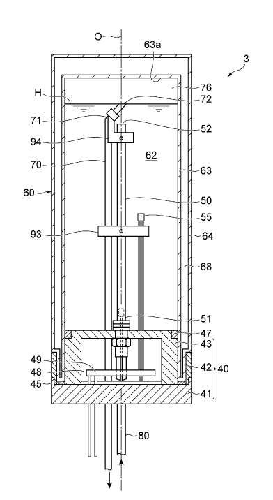
Literature 1, a washer fluid of the heat-retaining hot water storage
chamber may be allowed to flow into the heating chamber by opening
an outflow passage of the washer fluid at an upper part of the heating
chamber. After the washer fluid is heated by the electric heater inside
the heating chamber, the washer fluid is supplied to a washer nozzle by
driving of a washer pump and sprayed from the washer nozzle.
Citation List
Patent Literature
[0003] Patent Literature 1: Japanese Patent No. 5536680
Summary of Invention
Technical Problem
[0004] Incidentally, in a configuration in which the outflow passage is
open in the heating chamber of the washer fluid heating device, an air
1
CA 02969195 2017-05-29
FP15-0525-00
layer may be formed above the washer fluid. In this case, a distal end
portion of the heater may be exposed from the washer fluid when the
vehicle is inclined while the washer fluid heating device is turned ON or
the washer fluid heating device is obliquely attached. This exposed
distal end portion causes a so-called no-water burning state, and steam
of the washer fluid is generated when the washer fluid comes into
contact with the distal end portion in this state. When the steam of the
washer fluid is sprayed from the washer noz7le and cooled, the steam
becomes white steam and a failure of the vehicle may be erroneously
recognizes. In addition, a part of the heating means partially becomes
hot, and thus the heating device is easily damaged.
[0005] An object of the invention is to provide a washer fluid heating
device capable of preventing a phenomenon such as steaming from
occurring and preventing damage to the heating device even when an air
layer is formed above a washer fluid.
Solution to Problem
[0006] A washer fluid heating device of an aspect of the invention
includes a container that contains a washer fluid, a lid portion attached
to a first end of the container in a direction of a central axis line to face
an accommodation space for the washer fluid, heating means that has a
proximal end portion attached to the lid portion and extends toward the
accommodation space, and an outflow pipe having an outlet disposed in
the accommodation space to allow the washer fluid in the
accommodation space to flow out, wherein the outlet is provided
between a distal end surface of the heating means and a second end
opposite to the first end of the container, and a region obtained by
2
CA 02969195 2017-05-29
FP15-0525-00
projecting the outlet onto a virtual plane perpendicular to the direction
of the central axis line of the container at least partially overlaps a
region obtained by projecting the distal end surface of the heating
means onto the virtual plane.
[0007] According to the washer fluid heating device of the aspect of the
invention, the lid portion is attached to the first end of the container, and
the heating means, the proximal end portion of which is attached to the
lid portion, extends in the accommodation space of the container. The
outflow pipe having the outlet which allows the washer fluid in the
accommodation space to flow out is disposed in the accommodation
space of the container. The outlet is provided between the distal end
surface of the heating means and the second end opposite to the first end
of the container. In other words, when the washer fluid heating device
is used, a distal end portion of the heating means is located in the
washer fluid and is rarely exposed from the washer fluid. In addition,
the projection region obtained by projecting the outlet onto the virtual
plane perpendicular to the direction of the central axis line of the
container at least partially overlaps the projection region obtained by
projecting the distal end surface of the heating means onto the virtual
plane. In this case, the distal end portion of the heating means is
located on the first end side of the container from the horizontal plane
passing through the outlet regardless of a direction in which the washer
fluid heating device is inclined. Therefore, even when the washer fluid
heating device is inclined, the distal end portion of the heating means is
rarely exposed to an upper side of the washer fluid, and a phenomenon
such as steaming may be prevented from occurring.
3
CA 02969195 2017-05-29
FP15-0525-00
[0008] In addition, the outlet may be provided on an axis of the heating
means. In this case, the outlet is located immediately above the
heating means, and thus the phenomenon such as steaming is
suppressed even when the washer fluid heating device is greatly
inclined.
[0009] In addition, the outlet may be provided on the central axis line of
the container. In this case, regardless of the direction in which the
washer fluid heating device is inclined, the amount of the washer fluid
contained in the container is not greatly reduced, and the washer fluid
heating device may be efficiently used.
[0010] In addition, the outflow pipe may be fixed by a fixing member
attached to the distal end portion of the heating means. In this case,
since the distal end portion of the outflow pipe is fixed, a position of the
outlet is stable. Therefore, a liquid level of the washer fluid is more
stably maintained. In addition, since a relative position between the
distal end portion of the heating means and the outlet is kept constant, it
is possible to reduce a possibility that a distal end of the heating means
will protrude to the air layer to cause a no-water burning state.
Effects of Invention
[0011] According to an aspect of the invention, a phenomenon such as
steaming may be prevented even when an air layer is formed above a
washer fluid.
Brief Description of Drawings
[0012] FIG 1 is a diagram schematically illustrating a washer fluid
supply system using an embodiment of the invention.
FIG 2 is an exploded perspective view illustrating a washer
4
CA 02969195 2017-05-29
FP15-0525-00
fluid heating device of FIG 1.
FIG 3 is a planar cross-sectional view illustrating the washer
fluid heating device of FIG. 1.
FIG 4 is a cross-sectional view taken along IV-IV of FIG 3.
FIG 5 is a side cross-sectional view illustrating a case in which
the washer fluid heating device of FIG 1 is inclined.
FIGS. 6A and 6B are side cross-sectional views illustrating a
case in which the washer fluid heating device of FIG 1 is inclined, and a
liquid level of a washer fluid passes through an outlet.
FIG 7 is a cross-sectional view taken along VII-VII of FIG 3
and is a schematic view illustrating an inlet and a current plate of the
washer fluid heating device.
Description of Embodiments
[0013] Hereinafter, an embodiment of the invention will be described
with reference to drawings. In description of the drawings, the same
reference numeral will be assigned to the same element, and a repeated
description will be omitted.
[0014] Hereinafter, a description will be given of an example in which a
washer fluid heating device 3 according to an embodiment of the
invention is applied to a washer fluid supply system of a vehicle. As
illustrated in FIG 1, a washer fluid supply system 10 includes a washer
fluid tank 1 that stores a washer fluid, a washer fluid pump 2 provided
at an outlet side of the washer fluid tank 1, and a washer fluid nozzle 8
provided to face a front windshield of the vehicle. The supply system
10 further includes the washer fluid heating device 3 provided between
the washer fluid pump 2 and the washer fluid nozzle 8. An operation
5
CA 02969195 2017-05-29
FP15-0525-00
unit 6 is connected to the washer fluid pump 2 and the washer fluid
heating device 3. The washer fluid pump 2 may be operated when the
operation unit 6 is operated by a driver of the vehicle, etc. The above
respective devices are connected by a pipe line 7. The washer fluid
tank 1 is connected to an injection hole for the washer fluid througjh the
pipe line 7.
[0015] As illustrated in FIG. 2 to FIG 4, the washer fluid heating device
3 includes a cylindrical container 60, a lid portion 40 attached to a first
end of the container 60 in a direction of a central axis line 0 to close an
opening 61 of the container 60, and heating means 50 attached to the lid
portion 40. The container 60 has a cylindrical accommodation space
62 that contains the washer fluid. A proximal end portion 51 of the
heating means 50 is attached to the lid portion 40 and the heating means
50 extends toward the accommodation space 62 of the container 60.
Here, the proximal end portion 51 of the heating means 50 corresponds
to a portion of the heating means 50 on a first end side in the direction
of the central axis line 0.
[0016] The container 60 is fixed inside the vehicle by a plate-shaped
support member 92 and a fixing band 91. The container 60 has a
double structure similar to that of a thermos bottle and has a heat
insulating structure for keeping the washer fluid in the accommodation
space 62 warm. For example, an inner wall 63 of the container 60 is
made of metal such as stainless steel, glass plated with metal, etc. An
outer wall 64 of the container 60 is made of metal such as stainless
steel. A vacuum layer 68 is formed between the inner wall 63 and the
outer wall 64.
6
CA 02969195 2017-05-29
FP15-0525-00
[0017] At the first end of the container 60 at which the opening 61 is
formed, a screw portion 65 is formed on an outer peripheral surface
thereof and a screw portion 66 is formed on an inner peripheral surface
thereof. In the present embodiment, a term "lower" means the first end
side with respect to the container 60, that is, the side of the lid portion
40.
[0018] The lid portion 40 faces the accommodation space 62 for the
washer fluid and seals the accommodation space 62. The lid portion
40 includes an inner plug 43 facing the accommodation space 62, a
cover 42 attached to the screw portion 65 provided on the outer
peripheral surface of the opening 61, and an outer lid 41 attached to the
cover 42 to cover a lower surface of the inner plug 43. The outer lid
41 is attached to the cover 42 by being screwed into a screw portion 44
formed on a lower side of an outer peripheral surface of the cover 42.
Annular packing 45 (see FIGS. 4 and 5) is provided between the outer
lid 41 and an end surface of the container 60 on the opening 61 side.
For example, each member included in the lid portion 40 is made of a
resin such as polyphenylene sulfide (PPS), polypropylene (PP), etc.
[0019] A screw portion 46 is formed on an outer peripheral surface of
the inner plug 43. The inner plug 43 is attached to the container 60 by
screwing the screw portion 46 and the screw portion 66 of the opening
61 of the container 60. A groove portion for mounting packing 47 is
formed along an outer peripheral portion thereof on an upper surface of
the inner plug 43. The opening 61 of the accommodation space 62 is
sealed by the inner plug 43 and the packing 47. A depression 48 which
is recessed to the accommodation space 62 side and open downward is
7
CA 02969195 2017-05-29
FP15-0525-00
formed in the inner plug 43. The depression 48 is filled with a resin
such as urethane, and a control board 49 is buried therein.
[0020] The heating means 50 is mounted by the proximal end portion
51 thereof penetrating the inner plug 43. The heating means 50
extends toward a second end side opposite to the lid portion 40. An
axis of the heating means 50 is located on the central axis line 0 of the
container 60. A distal end surface 52 is formed on a distal end side of
the heating means 50 in an axial direction. Here, a distal end portion
of the heating means 50 refers to a portion on a distal end side of a
central portion of a portion extending in the accommodation space 62.
The distal end surface 52 of the heating means 50 has a planar shape.
However, the distal end surface 52 may have a curved surface shape
other than the planar shape such as a mountain shape, a depression, a
projection, etc.
[0021] A temperature sensor 55 is provided around a central portion of
the accommodation space 62 in an extending direction. The
temperature sensor 55 is connected to the control board 49
accommodated in the depression 48 of the inner plug 43 by a lead wire.
The lead wire of the temperature sensor 55 is held by a first holder 93
attached to the heating means 50 around the central portion of the
accommodation space 62 in the extending direction.
[0022] The temperature sensor 55 measures a temperature around the
central portion of the accommodation space 62. The temperature
sensor 55 may measure a temperature, and examples thereof include a
thermistor, a thermocouple, etc. The temperature sensor 55 measures a
temperature of the washer fluid in the accommodation space 62 and
8
CA 02969195 2017-05-29
FP15-0525-00
outputs the measured temperature to the control board 49. Heating
adjusting means 20 (see FIG 1) controls ON/OFF of the heating means
50 based on the temperature measured by the temperature sensor 55.
In this way, the temperature of the washer fluid in the accommodation
space 62 is maintained at a desired temperature (for example, about
40 C).
[0023] The container 60 is provided with an outflow pipe 70 for
allowing the washer fluid to flow out and an inflow pipe 80 for allowing
the washer fluid to flow in. The outflow pipe 70 is connected to the
washer fluid nozzle 8 by the pipe line 7. The inflow pipe 80 and the
outflow pipe 70 penetrate the lid portion 40 to extend in the
accommodation space 62. The inflow pipe 80 is connected to the
washer fluid pump 2 by the pipe line 7.
[0024] The outflow pipe 70 has a bent portion 71 bent to an upper side
of the heating means 50 and an outlet 72 formed at a distal end of the
bent portion 71. The outflow pipe 70 for the washer fluid is fixed
around the central portion of the accommodation space 62 in the
extending direction by the first holder 93 attached to the heating means
50. The bent portion 71 of the outflow pipe 70 is fixed by a second
holder 94 (fixing member) attached to the distal end portion of the
heating means 50. One end of the second holder 94 extends to the
upper side of the heating means 50 to form an annular member. The
annular member is fixed by allowing the bent portion 71 to pass
therethrough. The second holder 94 is made metal, resin, etc. having
heat resistance.
[0025] Next, a description will be given of the outlet 72 that allows the
9
CA 02969195 2017-05-29
FP15-0525-00
washer fluid to flow out, the distal end surface 52 of the heating means
50, and a liquid level H of the washer fluid with reference to FIG 3 to
FIG 6. FIG 3 is a planar cross-sectional view illustrating the washer
fluid heating device of FIG. 1. FIG. 4 is a cross-sectional view taken
along IV-IV of FIG 3. FIG 5 is a side cross-sectional view illustrating
a case in which the washer fluid heating device 3 of FIG 1 is inclined.
FIGS. 6A and 6B are side cross-sectional views illustrating a case in
which the washer fluid heating device of FIG 1 is inclined, and a liquid
level of a washer fluid passes through an outlet.
[0026] The outlet 72 of the outflow pipe 70 is located at an upper side
of the accommodation space 62. The outlet 72 forms an annular shape
extending along a surface perpendicular to the central axis line 0 of the
container. In addition, the outlet 72 is located at a position at which
the washer fluid is 90% or less of a volume of the accommodation space
62 in a vertical direction of the container 60. That is, a flat cylindrical
space 76 formed by a horizontal plane passing through the outlet 72 and
an inner wall surface 63a of the accommodation space 62 on the second
end side corresponds to 10% or more of the volume of the
accommodation space 62. This space 76 corresponds to an air layer
above the washer fluid.
[0027] Here, a description will be given of a positional relation between
the outlet 72 and the distal end surface 52 of the heating means 50.
The outlet 72 is provided between the distal end surface 52 of the
heating means 50 and the second end of the container 60 in the
accommodation space 62. In other words, the outlet 72 is separated
from the lid portion 40 more than the distal end surface 52 of the
CA 02969195 2017-05-29
FP15-0525-00
heating means 50. A region obtained by projecting the outlet 72 onto a
virtual plane perpendicular to the central axis line 0 of the container 60
is included in a region obtained by projecting the distal end surface 52
of the heating means 50 onto the virtual plane perpendicular to the
central axis line 0 of the container 60 (see FIG 3). That is, the region
obtained by projecting the outlet 72 onto the virtual plane perpendicular
to the central axis line 0 of the container 60 overlaps a part of the region
obtained by projecting the distal end surface 52 of the heating means 50
onto the virtual plane perpendicular to the central axis line 0 of the
container 60. In addition, the outlet 72 is disposed to be located on the
axis of the heating means 50. That is, the outlet 72 is disposed to be
located directly above the distal end surface 52 of the heating means 50
in the direction of the central axis line 0 of the container 60.
[0028] As illustrated in FIG 4, the liquid level H of the washer fluid
stored in the accommodation space 62 of the container 60 substantially
matches the horizontal plane passing through the outlet 72. The liquid
level H of the washer fluid stored in the accommodation space 62 of the
container 60 refers to a normal water level of the washer fluid when the
washer fluid pump 2 is in an OFF state. When the washer fluid pump
2 is used, air corresponding to a compressive fluid may be compressed
and the washer fluid may be maintained above the liquid level H of the
washer fluid. In addition, when the vehicle is tilted while the washer
fluid pump 2 is in the OFF state, the liquid level of the washer fluid
stored in the accommodation space 62 of the container 60 is, for
example, a liquid level H1 as illustrated in FIG 5. In this case, a space
76 having a volume of 10% or more of the volume of the
11
CA 02969195 2017-05-29
FP15-0525-00
accommodation space 62 is formed between the liquid level H1 and the
inner wall surface 63a of the accommodation space on the second end
side. A shape of the space 76 corresponds to a shape obtained by
obliquely cutting out a part of a ridge portion of a cylinder.
[0029] FIG 5 illustrates a state in which the washer fluid heating device
3 is inclined by an angle a, for example, 40 with respect to a horizontal
plane. As illustrated in FIG 5, the liquid level H1 of the washer fluid
is formed above the outlet 72. The outlet 72 is located above the distal
end surface 52 of the heating means 50. In other words, the distal end
surface 52 of the heating means 50 is located below the liquid level H1
of the washer fluid and is not exposed from the liquid level of the
washer fluid. In addition, the liquid level H1 of the washer fluid may
be maintained without change. However, in some cases, air may enter
the container 60 through the inlet 81 or the outlet 72, so that a liquid
level H2 of the washer fluid is formed to pass through the outlet 72 as
illustrated in FIG 6A. In this case, the distal end surface 52 of the
heating means 50 is located below the liquid level 142 of the washer
fluid and is not exposed from the liquid level of the washer fluid. The
liquid level of the washer liquid fixated along the horizontal plane
passing through the outlet 72 is a lowest liquid level among liquid levels
that can be formed in the accommodation space 62 inside the container
60.
[0030] In addition, as illustrated in FIG 6B, the washer fluid heating
device 3 may be inclined by an angle 13, for example, 40 with respect to
the horizontal plane in an opposite direction to that of the above
example. In this case, the distal end surface 52 of the heating means
12
CA 02969195 2017-05-29
FP15-0525-00
50 is located below the liquid level H2 of the washer fluid passing
through the outlet 72. That is, the distal end surface 52 of the heating
means 50 is located below a liquid level formed along the horizontal
plane passing through the outlet 72 (the lowest liquid level among liquid
levels that can be formed) regardless of a direction in which the washer
fluid heating device 3 is inclined.
[0031] Even when the washer fluid heating device 3 illustrated in FIG 4
is inclined, the space 76 formed above the horizontal plane passing
through the outlet 72 corresponds to 10% or more of the volume of the
accommodation space 62. Examples of a case in which the washer
fluid heating device 3 is inclined include a case in which the vehicle is
inclined with respect to the horizontal plane or a case in which the
washer fluid heating device 3 is obliquely attached to the vehicle. For
example, when the washer fluid heating device 3 is obliquely attached at
25 with respect to the horizontal plane of the vehicle and the vehicle is
further inclined by 25 with respect to the horizontal plane in the same
direction, the washer fluid heating device 3 is inclined by 50 in total
with respect to the horizontal plane.
[0032] Here, a steaming phenomenon that can occur in a conventional
washer fluid heating device will be described. In a process of using
the washer fluid heating device, a washer fluid flowing into an
accommodation space is heated by heating means, then flows into an
outlet and is sent to the outside of a container. That is, when the outlet
is formed in the accommodation space, an air layer may be formed in an
upper part of the accommodation space. In this case, steam of the
washer fluid is generated when the heating means is overheated while a
13
CA 02969195 2017-05-29
FP15-0525-00
distal end portion of the heating means is exposed from a liquid level of
the washer fluid since a vehicle is inclined in a state in which the washer
fluid heating device is turned ON or the washer fluid heating device is
obliquely attached. When the steam of the washer fluid is sprayed
from a washer fluid nozzle via the outlet, the steam is cooled around the
washer fluid nozzle and becomes white steam.
[0033] Even though this steam is not a phenomenon caused by a failure
of the vehicle, a user of the vehicle, etc. may erroneously recognize that
a failure has occurred in the vehicle. In the washer fluid heating
device 3, the above-described steaming phenomenon may be prevented
by positioning the distal end surface 52 of the heating means 50 below
the lowest liquid level of the washer fluid regardless of a direction in
which the container 60 is inclined. In other words, the outlet 72 is
provided between the distal end surface 52 of the heating means 50 and
the second end opposite to the first end of the container 60. Then, the
outlet 72 and the distal end surface 52 of the heating means 50 are
disposed such that the projection region obtained by projecting the
outlet 72 onto the virtual plane perpendicular to the direction of the
central axis line 0 of the container 60 partially overlaps the projection
region obtained by projecting the distal end surface 52 of the heating
means 50 onto the virtual plane perpendicular to the direction of the
central axis line 0 of the container 60. According to this
configuration, the distal end portion of the heating means 50 is located
below the liquid level of the washer fluid regardless of the direction in
which the washer fluid heating device 3 is inclined, and the steam, etc.
is prevented from being generated.
14
CA 02969195 2017-05-29
FP15-0525-00
= [0034] Hereinafter, the inflow pipe for washer fluid and a current plate
will be described with reference to FIG 3 and FIG 7. FIG 3 is a
planar cross-sectional view illustrating the washer fluid heating device
of FIG 1. FIG 7 is a cross-sectional view taken along VII-VII of FIG
3 and is a schematic view illustrating the inlet and a current plate of the
washer fluid heating device.
[0035] As illustrated in FIG 3, the inflow pipe 80 (an inlet 81) for the
washer fluid is disposed on one side of a virtual plane connecting center
axes of the outflow pipe 70 for the washer fluid and the heating means
50. The inflow pipe 80 for the washing fluid penetrates the lid portion
40 and extends in the accommodation space 62. The inlet 81 is formed
at a distal end of the inflow pipe 80 for the washing fluid. The inlet 81
is disposed in a substantially lower half portion in the vertical direction
of the accommodation space 62. A current plate 83 of a rectification
member 84 (see FIG 7) is disposed above the inlet 81 to cover the inlet
81 when viewed from above.
[0036] The rectification member 84 has a standing plate 82 attached to
the inner plug 43 and the current plate formed by bending the standing
plate 82. The standing plate 82 is disposed between the heating means
50 and the inflow pipe 80 to be parallel to the virtual plane connecting
the center axes of the outflow pipe 70 and the heating means 50. An
upper end portion of the standing plate 82 is bent toward the inner wall
63 side to cover the inlet 81, thereby forming the current plate 83.
[0037] As illustrated in FIG. 7, the current plate 83 is located above the
inlet 81 and below the outlet 72. That is, the current plate 83 is
disposed between the inlet 81 and the outlet 72. An inclined direction
CA 02969195 2017-05-29
FP15-0525-00
of the current plate 83 is parallel to a virtual plane formed by the axis of
the outflow pipe 70 for the washer fluid and the central axis line 0 of
the container 60, and is inclined toward an opposite side to the outflow
pipe 70 with respect to the central axis line 0. Here, the inclined
direction of the current plate 83 is a normal direction of a plane forming
the current plate 83.
[0038] Here, a description will be given of a process after the washer
fluid flows into the accommodation space 62 of the container 60 in the
washer fluid heating device 3. The washer fluid sent by the washer
fluid pump 2 is sprayed into the accommodation space 62 from the inlet
81 through the inflow pipe 80. The washer fluid after spraying
collides with the current plate 83 of the rectification member 84 by
momentum. The current plate 83 changes a flow direction of the
washer fluid to rise obliquely along a tilt direction of the current plate
83. The washer fluid guided to a side of the container 60 to flow up to
the inner wall 63 continues to flow along the inner wall 63 while rising
in an oblique direction. As a result, the washer fluid flows to rise
along a helical direction F from the first end side to the second end side
in the accommodation space 62 inside the container 60. The washer
fluid flowing in from the inlet 81 moves toward the outlet 72 while
successively pushing up the heated washer fluid without directly
heading for the outlet 72 by rising along the helical direction F. In
addition, the washer fluid flowing in from the inlet 81 stays in the
accommodation space 62 for a long time and is sufficiently heated.
[0039] Next, a description will be given of a method of operating the
washer fluid supply system 10 using the washer fluid heating device 3
16
CA 02969195 2017-05-29
FP15-0525-00
of the present embodiment.
[0040] For example, the washer fluid heating device 3 operates when
the driver, etc. turns ON an ignition key. In this way, the washer fluid
in the accommodation space 62 is heated to a desired temperature by the
heating means 50. Subsequently, when an operation command is
delivered to the washer fluid pump 2 by the driver, etc. operating the
operation unit 6, the washer fluid stored in the washer fluid tank 1 is
supplied to the washer fluid heating device 3 by the washer fluid pump
2 and flows into the accommodation space 62 of the heating device 30
through the inflow pipe 80 for the washer fluid. In the accommodation
space 62, the washer fluid flowing in from the inlet 81 is heated while
spirally rising. At the same time, the washer fluid successively raises
the heated washer fluid present in an upper part of the accommodation
space 62. As a result, the heated washer fluid flows into the outlet 72
of the outflow pipe 70 for the washer fluid disposed in an upper region
of the accommodation space 62. The washer fluid in the outflow pipe
70 is delivered to the washer fluid nozzle 8 via the pipe line 7 by driving
the washer fluid pump 2. Through this series of operations, a warmed
washer fluid is supplied to the front windshield of vehicle.
[0041] Here, in the accommodation space 62 that contains the washer
fluid, the distal end surface 52 of the heating means 50 is located below
the horizontal plane passing through the outlet 72. That is, the distal
end surface 52 of the heating means 50 is located below the lowest
liquid level among the liquid levels that can be formed in the
accommodation space 62. Therefore, the steaming phenomenon may
be prevented from occurring even when the washer fluid heating device
17
CA 02969195 2017-05-29
FP15-0525-00
3 is inclined.
[0042] According to the above-described washer fluid heating device 3
of the present embodiment, the lid portion 40 is attached to the first end
of the container 60, and the heating means 50, the proximal end portion
51 of which is attached to the lid portion 40, extends in the
accommodation space 62 of the container 60. The outflow pipe 70
having the outlet 72 that allows the washer fluid in the accommodation
space 62 to flow out is disposed in the accommodation space 62 of the
container 60. The outlet 72 is provided between the distal end surface
52 of the heating means 50 and the second end opposite to the first end
of the container 60. In addition, the projection region obtained by
projecting the outlet 72 onto the virtual plane perpendicular to the
direction of the central axis line 0 of the container 60 overlaps a part of
the projection region obtained by projecting the distal end surface 52 of
the heating means 50 onto the virtual plane perpendicular to the
direction of the central axis line 0 of the container 60. In this case, the
distal end surface 52 of the heating means 50 is located on the first end
side of the container 60 from the horizontal plane passing through the
outlet 72 regardless of the direction in which the washer fluid heating
device 3 is inclined. Therefore, even when the washer fluid heating
device 3 is inclined, the distal end portion of the heating means 50 is
rarely exposed to an upper side of the washer fluid, and a phenomenon
such as steaming may be prevented from occurring. In addition, the
distal end portion of the heating means 50 may be prevented from
protruding to the air layer to cause a no-water burning state.
[0043] In addition, the outlet 72 is provided on the axis of the heating
18
CA 02969195 2017-05-29
FP15-0525-00
means 50. In other words, since the outlet 72 is located immediately
above the heating means 50, the phenomenon such as steaming may be
suppressed even when the washer fluid heating device 3 is greatly
inclined.
[0044] In addition, the outlet 72 is provided on the central axis line 0 of
the container 60. For this reason, regardless of the direction in which
the washer fluid heating device 3 is inclined, the amount of the washer
fluid contained in the container 60 is not greatly reduced, and the
washer fluid heating device 3 may be efficiently used.
[0045] In addition, since the outflow pipe 70 is fixed to the second
holder 94 (fixing member) attached to the distal end portion of the
heating means 50, a distal end portion of the outflow pipe 70 is fixed, a
position of the outlet 72 is stable, and the liquid level of the washer fluid
is more stably maintained. In addition, since a relative position
between the distal end portion of the heating means 50 and the outlet 72
is kept constant, the distal end portion of the heating means 50 may be
more reliably prevented from protruding to the air layer to cause the
no-water burning state.
[0046] Hereinbefore, the present embodiment has been described.
However, the invention is not limited to the above-described
embodiment, and various modified embodiments can be adopted. For
example, instead of forming the outlet 72 perpendicular to the central
axis line 0 of the container 60, a notch, etc. may be formed in a part of a
distal end of the outflow pipe 70, or the outlet 72 may be inclined with
respect to the central axis line 0. In this case, similarly to a case in
which the outlet 72 is perpendicular to the central axis line 0, the
19
CA 02969195 2017-05-29
FP15-0525-00
steaming phenomenon, etc. is suppressed when the distal end surface 52
of the heating means 50 is located below the horizontal plane passing
through the outlet 72.
[0047] In addition, a part of the projection region obtained by
projecting the outlet 72 onto the virtual plane perpendicular to the
direction of the central axis line 0 of the container 60 may overlap a
part of the projection region obtained by projecting the distal end
surface 52 of the heating means 50 onto the virtual plane perpendicular
to the direction of the central axis line 0 of the container 60. In this
case, similarly to the above-described embodiment, regardless of the
direction in which the washer fluid heating device 3 is inclined, the
steaming phenomenon, etc. is suppressed when the distal end portion of
the heating means 50 is located below the horizontal plane passing
through the outlet 72.
[0048] In addition, in the above embodiment, the outflow pipe 70 is
fixed by the fixing member attached to the heating means 50.
However, the fixing member may not be provided when the outflow
pipe 70 is made of a hard material, etc. Further, in the above
embodiment, the container 60 and the accommodation space 62 are
cylindrical. However, the invention is not limited thereto. For
example, each of the container 60 and the accommodation space 62 may
have a polygonal columnar shape or an elliptical columnar shape.
[0049] In the above embodiment, the outlet 72 is located immediately
above the distal end surface 52 of the heating means 50 by bending the
distal end portion of the outflow pipe 70. However, the outlet 72 may
be located immediately above the heating means 50 by obliquely
CA 02969195 2017-05-29
FP15-0525-00
disposing the outflow pipe 70 with respect to the heating means 50. In
addition, the outlet 72 may not be located immediately above the distal
end surface 52 of the heating means 50.
[0050] In the above embodiment, the heating means 50 is disposed such
that the axis of the heating means 50 is located on the central axis line 0
of the container 60. However, the invention is not limited thereto.
For example, the heating means 50 may be obliquely attached with
respect to the central axis line of the container 60.
Industrial Applicability
[0051] According to an aspect of the invention, a phenomenon such as
steaming may be prevented even when an air layer is formed above a
washer fluid.
Reference Signs List
[0052] 3... washer fluid heating device, 40... lid portion, 50... heating
means, 51... proximal end portion, 52... distal end surface of heating
means, 60... container, 62... accommodation space, 63... inner wall,
70... outflow pipe, 72... outlet, 80... inflow pipe, 81... inlet, 83...
current plate, 94... second holder, 0... central axis line of container.
21