Note: Descriptions are shown in the official language in which they were submitted.
CA 02969253 2017-05-30
WO 2016/109890
PCT/CA2016/050006
SYSTEMS AND METHODS FOR SUPER-RESOLUTION COMPACT
ULTRASOUND IMAGING
CROSS REFERENCE TO RELATED APPLICATION
100011 The
present application claims the benefit of U.S. provisional patent
application no. 62/099,680 filed on January 5, 2015 and entitled SYSTEMS AND
METHODS FOR SUPER-RESOLUTION COMPACT ULTRASOUND IMAGING, the entire
contents of which are incorporated herein by reference.
FIELD OF INVENTION
[0002] The
present disclosure relates to systems and methods for medical
imaging and, in particular, to ultrasound imaging. Certain examples of the
disclosure
provide systems and methods for super-resolution compressed ultrasound imaging
capable of micrometer resolutions. This disclosure comprises of systems and
methods
for (i) acquisition; and (ii) processing of ultrasound imaging data.
BACKGROUND
[0003]
Ultrasound is an imaging modality that is relatively cheap, risk-free,
radiation-free and portable.
[0004]
However, in some applications, the resolution of ultrasound images is
very low, limiting the application of this imaging modality. For example,
ultrasound
brain vascular imaging has not been clinically achieved due to spatial
resolution
limitation in ultrasound propagation through the human skull; this limits the
application of ultrasound in Traumatic Brain Injury (TBI) for emergency
situations.
Another example is breast cancer screening where ultrasound is not solely and
frequently used for population-based screening of the breast cancer due to
ultrasound-
limited resolution.
[0005] The
second problem with ultrasound is that in some applications, there is
a need to use a large number of transducers (sometimes as high as a couple of
thousands) producing several hundreds of frame rate per second and each frame
has
several of hundreds of image lines. Therefore, the processing power is high in
current
ultrasound machines to be able to process a large amount of data in real-time.
In order
to use ultrasound in emergency and point-of-care applications, the imaging
system
should be compact with lower acquisition and processing requirements.
[0006]
Therefore, there are two aspects in improving the performance of current
ultrasound systems (i) to improve the image quality not by increasing the
quantity of
the acquired data; and (ii) to accelerate the acquisition and processing rates
and at the
same time not dropping the quality in terms of image resolution, Signal-to-
Noise ratios
1
CA 02969253 2017-05-30
WO 2016/109890
PCT/CA2016/050006
(SNRs), and contrast.
100071
Compressive sensing (CS) approaches provide an alternative to the
classical Nyquist sampling framework and enable signal reconstruction at lower
sampling rates, for example by Candes et. al., in "Robust uncertainty
principles: exact
signal reconstruction from highly incomplete frequency information," IEEE
Transactions on Information Theory, vol. 52, no. 2, pp. 489-509, Feb 2006. The
idea of
CS is to merge the compression and sampling steps. In recent years, the area
of CS has
branched out to a number of new applications like radar, communications, and
ultrasound imaging.
100081 All the
proposed CS approaches in ultrasound imaging is using a non-
adaptive beamforming ("spatial filtering") to reconstruct the final image in
ultrasound.
This non-adaptive beamforming in based on a Delay-and-Sum (DAS), which is a
preferred beamforming method in current ultrasound machines. In the DAS
approach,
relevant time-of-flights from each transducer element to each point in the
region of
interest (ROT) are compensated and then a summation is performed on all the
aligned
observations to form the image. The DAS beamformer is independent of data with
fixed
weights and in order to apply this techniques in time domain, the data samples
should
be high enough even more than the rate dictated by the Shannon-Nyquist
theorem.
Now, combining DAS with CS provides lower resolution as compared to applying
super
resolution techniques like Time Reversal MUltiple Signal Classification (TR-
MUSIC) and
Capon methods.
100091 The
time reversal (TR)-based imaging methods utilize the reciprocity of
wave propagation in a time-invariant medium to localize an object with higher
resolution. The focusing quality in the time-reversal method is decided by the
size of the
effective aperture of transmitter-receiver array. This effective aperture
includes the
physical size of the array and the effect of the environment. A complicated
background
will create the so-called multipath effect and can significantly increase the
effective
aperture size, which enhances the resolution of the acquired images.
100101 Most of
the previous computational time reversal based imaging methods
uses the eigenstructure of the TR matrix to image the targets. Generally, the
singular
value decomposition (SVD) of the TR matrix is needed for every frequency bin
and for
every space-space TR-matrix. For ultrawideband (UWB) imaging, the SVDs of
space-
space TR matrices are utilized and combined to form the final image. There are
two
problems with this configuration: (i) the computational complexity of
repeating the SVD
of the TR matrix in every frequency bin is very high limiting the usage of
this technique
in real-time ultrasound system and (ii) at each frequency, the singular
vectors have an
arbitrary and frequency- dependent phase resulted from the SVD.
100111 In UWB
TR_MUSIC method, only the magnitude of the inner products are
combined along the bandwidth and these arbitrary phases cancel out, therefore,
the
problem of incoherency does not exist for non-noisy data. However, the super-
resolution property of TR-MUSIC disappears as the signals become noisy which
is due to
the random phase structure induced by noise. A modified version of TR-MUSIC,
Phase
Coherent MUSIC (PC-MUSIC) uses a re-formulation of TR-MUSIC, which retains the
phase information and also applies averaging of the pseudospectrum in
frequency to
2
CA 02969253 2017-05-30
WO 2016/109890
PCT/CA2016/050006
cancel out the random phase degradation of TR-MUSIC in case of noisy data. The
problem with PC-MUSIC is that since it uses phase information and disregards
the phase
response of the transducers, its ability to localize the targets at their true
locations is
adversely impacted as explained in "Super-resolution ultrasound imaging using
a phase-
coherent MUSIC method with compensation for the phase response of transducer
elements," IEEE Transactions on Ultrasonics, Ferroelectrics, and Frequency
Control, vol.
60, no. 6, pp. 1048-1060, June 2013.
[0012] A
modification to PC-MUSIC was proposed by Labyed et al. to compensate
the transducer phase response by developing an experimental method to estimate
the
phase responses beforehand. The computational complexity of this modification
is still
high as the SVD is needed for every frequency bin across the bandwidth and the
image
is formed by averaging these pseudospectrums for points in the region- of-
interest
(ROI). Also, the efficiency of this incoherent approach depends on the SNRs of
the
individual frequency bins.
[0013]
Frequency matrices were proposed previously by Kaveh et al. in
"Focusing matrices for coherent signal-subspace processing," IEEE Transactions
on
Acoustics, Speech and Signal Processing, vol. 36, no. 8, pp. 1272-1281, Aug
1988, for
finding the direction-of-arrival of multiple wideband sources using passive
arrays. Li et.
al modified these matrices to be used in active arrays with robust Capon
beamformers
in ultrasound imaging.
BRIEF SUMMARY OF THE INVENTION
[0014] An
embodiment of the present invention that is described herein provides
a method comprising of sending ultrasound plane wave to a ROI comprising of
multiple
point scatterers form the transducer elements of the array sequentially, a low-
dimensional data acquisition method to receive the backscatters from the
medium by all
the transducer elements and a super-resolution image reconstruction method to
form
the final image of the ROI irrespective of the sparsity of the received
signals.
[0015] In
disclosed embodiment, the low-dimensional acquisition method is
based on the principle of compressive sensing and sparse recovery. By way of
example,
the sensing matrices are based on random Gaussian matrices and the recovery is
based
on Fourier transform or wave atom of the received data channel. The reader is
referred
to the following publication that is hereby expressly incorporated by
reference and is
written by the current writer of this patent application: "Wave Atom Based
Compressive
Sensing and Adaptive Beamforming for Ultrasound Imaging", IEEE ICASSP 2015,
PP.
2474-2478.
[0016] By way
of example, sub-Nyquist sampling schemes that can be used in the
low-dimensional sampling by unit 303 are described by Gedalyahu et al., in
"Multichannel Sampling of Pulse Streams at the Rate of Innovation," IEEE
Transactions
on Signal Processing, volume 59, number 4, pages 1491-1504, 2011, which is
incorporated herein by reference. Example hardware that can be used for this
purpose
is described by Baransky et al., in "A Sub-Nyquist Radar Prototype: Hardware
and
Algorithms," IEEE Transactions on Aerospace and Electronics Systems, pages 809-
822,
April 2014, which is incorporated herein by reference.
3
CA 02969253 2017-05-30
WO 2016/109890
PCT/CA2016/050006
[0017] In
another embodiment, the recovered signals in frequency are used to
form the full data matrix. The beamforming uses focused frequency time
reversal
(FFTR) matrices to focus in frequency for UWB ultrasound signals, as well as
time
reversal Phase Coherent MUltiple Signal Classification (PC-MUSIC) algorithm to
focus
spatially on the target location. This combined method, which is referred to
as FFTR-
PCMUSIC, is motivated by the pressing need to improve the resolution of
diagnostic
ultrasound systems. Compared with the TR matched filter (TRMF) and incoherent
TR-
MUSIC approaches, the method proposed in this disclosure has lower
computational
complexity, higher visibility, higher robustness against noise, and higher
accuracy for
imaging point targets when the targets are micrometer distance apart. The
reader is
referred to the following publication that is hereby expressly incorporated by
reference
and is written by the current writer of this patent application: "Super-
resolution Ultra-
wideband Ultrasound Imaging using Focused Frequency Time Reversal MUSIC", IEEE
ICASSP, 2015, 887-891.
[0018] The
FFTR-PCMUSIC uses the TR focusing in time and space to achieve
high temporal and spatial resolution. The background Green's function at the
focused
frequency is used as the steering vector to form the final image. This method
reduces
the effect of noise on target localization accuracy as well as the
computational
complexity needed for subspace-based methods for UWB ultrasound data by using
frequency-focusing matrices together with the focused frequency Green's
function.
Effectively, the maximum resolution achieved by the FFTR-PCMUSIC is inherently
limited by the SNR and the bandwidth of the transducers.
BRIEF DESCRIPTION OF THE DRAWINGS
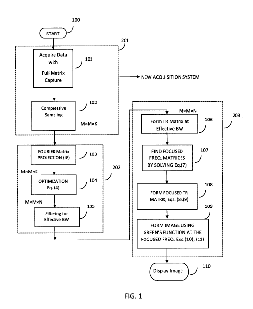
[0019] FIG. 1
is a flowchart setting forth the steps of the proposed method for
compact acquisition and reconstruction of a high-resolution image in an
ultrasound
system.
[0020] FIG. 2
is a block diagram of an example of an ultrasound system using this
method.
[0021] FIG. 3
shows the hardware of the system using the functional diagrams
presented in figures 1 and 2.
[0022] FIG. 4
shows the signal path of an example transmit-receive path from
each transmitter transducer to M receiver transducers considered in accordance
with
an embodiment of the present invention. This path is repeated for each
transmitter in
the array.
[0023] FIG. 5
shows the geometry of a 2D array of transducer with 2D ROI, in
accordance with an embodiment of the present invention.
[0024] FIG. 6,
by way of example, shows a simulation of the ROI with 2, 3, and 10
4
CA 02969253 2017-05-30
WO 2016/109890
PCT/CA2016/050006
point targets and the results from applying the method presented in this
disclosure.
[0025] FIG. 7, by way of example, shows a real ultrasound data from a wire
phantom and point targets after applying the method presented in some of the
embodiments of this invention.
DETAILED DESCRIPTION OF INVENTION
[0026] The transducer array (M transducers) shown in Fig. 3 as "301" sends
a
short pulse generated by way of example from the transmit waveform (Fig. 4,
"400")
sequentially from each transducer to the medium. The medium comprises of point
scatterers as shown in Fig. 5, "502" embedded in a medium speckle noise. The
data
signals are recorded through the received circuitry as shown in Fig. 4, "402"
using the
receive transducer array (units "301" or "500").
[0027] All the transducers in the array are sending a plane wave one by one
and
the same transducer array receives and records the backscatters from the
medium. As
shown in Fig. 5, "502", the point scatterers are located at r1 in the ROI. Due
to a probing
signal f1(t) sonicated by the transducer], a pressure filed is generated at
the location of
the scatterer as q (r , t) = q1 (t) 8(r1), where (r1) is delta function at
point r1 with
strength q (t) which depends on the probing signal fi (r), the attenuation of
the medium
in forward direction, the electromechanical impulse response of the transmit
transducer. By way of example, in frequency domain, the field generated at the
scatterer
location is Q (r1 , co).
[0028] The Green's function of the medium is the spatio-temporal impulse
response of the medium shown as "501" in FIG. 5. By way of example, in
frequency
domain the integral of the medium Green's function over the surface of the
transducer,
is given as following.
G (zi, r1, (o) =11sf ____________________ dS (1),
47r z,1
where z1 is the location of the transducer i array as shown as unit "500" in
FIG. 5, and
k = ¨ ¨ ia , with c being the sound propagation speed, and a is the amplitude
of the
attenuation coefficient of the environment, see "Super-resolution ultrasound
imaging
using a phase-coherent MUSIC method with compensation or the phase response of
transducer elements," IEEE Transactions on Ultrasonics, Ferroelectrics, and
Frequency
Control, vol. 60, no. 6, pp. 1048-1060, June 2013.
[0029] The pressure filed at the received transducer location i is
y (co) = (co) Q (r , co) G (z r 1, co) + v ij (co) (2),
where H1 (u) is the forward-backward frequency response of the transducers i
and],
and v11(&) is the measurement noise.
[0030] The signals y (co) is filtered and sparsified in the frequency
domain by
way of example using a wavelet de-noising tool as shown in FIG.4, unit "406".
CA 02969253 2017-05-30
WO 2016/109890
PCT/CA2016/050006
100311 The
filtered signal yii (a)) is down-sampled ("102") to 1/k'th of the
original samples using the random sensing matrices 4= , reducing the sampling
matrix
size to K x M, with K << N as follows:
xii = 4= yii +e (3)
where xii is the down-sampled data at transducer i and e is the measurement
error.
This phase is just to get the down-sampled data and in practice, this stage is
the output
of the modified data acquisition system of an ultrasound system shown in Fig.
2 as
"201". This modified data acquisition system is called low-dimensional
acquisition
system in this disclosure.
100321 In
recovery, a regularized-11 optimization is used to find the sparsest
solution of yi by way of example as the wave atom basis or Fourier basis. The
optimization problem is
-1 II 40 yii ¨ xij 112+ r II IP y1 111, (4)
2
where 111 is the wave atom or Fourier dictionary, r is a regularization
parameter, and
11.112, 11.111 are /2- and 11- norms of the vectors. The minimization formula
in (4) finds the
signals yij . This step is shown in Fig. 1 as 103, 104 and 202 in Fig. 2. In
various
embodiments, unit 104 may solve the optimization problem of Equation (4) in
any
suitable way. Example optimization schemes that can be used for this purpose
are
second-order methods such as interior-point methods described by Candes and
Romberg, in "11-magic: Recovery of Sparse Signals via Convex Programming,"
October,
2005; and by Grant and Boyd, in "The CVX User's Guide," CVX Research, Inc.,
November,
2013; and YALL1 basic models and tests by J. Yang and Y. Zhang. "Alternating
direction
algorithms for L1-problems in compressive sensing", SIAM Journal on Scientific
Computing, 33, 1-2, 250-278, 2011, which are incorporated herein by reference.
100331 The
signals yi are filtered to increase the SNR before going to the
beamforming process as shown in unit 105.
100341 In
practice, the step in 100311 is not needed and it is directly acquired at
the modified data acquisition of the ultrasound system shown in Fig.2, 201.
Here, it is
performed offline for the sake of conceptual clarity.
100351 After
recovery of signals, to beamform the M signals for image
reconstruction, the FFTR-PCMUSIC method is used as shown in Fig.4., "409".
This
method uses TR focusing frequency matrices to focus on frequency first and
then uses
the focused frequency TR matrix and a modified MUltiple Signal Classification
(MUSIC)
algorithm to focus spatially on the target location as shown in blocks 106-109
in FIG.1.
100361 This
method uses the TR-PCMUSIC in conjunction with TR-based
frequency focusing matrices to reduce the computational complexity of
incoherent TR-
MUSIC as well as phase ambiguity of the PCMUSIC in a noisy ultrasound
environment. In
FFTR-PCMUSIC, the SVD is applied once into a focused frequency TR matrix
through
finding unitary focusing matrices and applying a weighted averaging of the
focused TR
matrix over the bandwidth. This averaging reduces the effect of noise in space-
space
FFTR-PCMUSIC since the signal subspace is used after focusing in frequency.
Also, after
forming the FFTR matrix, the signal and noise subspaces are used once in
forming the
6
CA 02969253 2017-05-30
WO 2016/109890
PCT/CA2016/050006
pseudo-spectrum which peaks at the locations of the point targets.
[0037] In step
100291 we have the reconstructed signal -9 ,õ denoting Q as the
frequency band of interest after signal sparsifying in frequency domain, and
cog being
the frequency of each band. Then, we have Q of M X M space-space matrices
lOcuq) as
follows.
lOcuq) = F(cuq) ti ti g (c)q, r1) gT (cog, r1) + v((iq) (5)
where L is the number of scatterers shown in FIG. 5 as "502", and the green's
vector
g(coq, ri) = ei0((dci)[ G(z1,r1, co) , ...,G(zm,r(, co)] AT (6),
F(coq) takes care of both the field generated at the source location Q i(r ,
co) and the
frequency response of the transducers, assuming all to be the same. The
frequency
dependent phase of the transducer is denoted as (I)((uq).
[0038] In
practice, the transducer phase response can be calculated by
experimenting on a single point target embedded at a known location of a
homogeneous
environment, as demonstrated in "Super-resolution ultrasound imaging using a
phase-
coherent MUSIC method with compensation or the phase response of transducer
elements," IEEE Transactions on Ultrasonics, Ferroelectrics, and Frequency
Control, vol.
60, no. 6, page. 1048-1060, June 2013.
r
[0039] The TR
matrix T(cuq) = K(cuq) Kvuq) is computed at every frequency
bin. In order to find the focused frequency TR matrix -i' ) 0) , I am using
the unitary
matrices B(cuq) to minimize the difference between T((u0) and the transformed
TR
matrix at frequency q with the following minimization problem.
min II K(coor ¨ B(cuq)K(cuq)H IIF (7)
r
Subject to B(cuq) Bvuq) = /,
where II. IIF is the Frobenious norm. The solution to this problem is given as
B(6)q) = V(6)q)U(cuq)H, (8)
where V(600 and 1/(cuq) are the right and left singular vectors of the TR
matrix
K(C)O1K(a)0). Then, the coherently focused TR operator is the weighted average
of the
transformed matrix of TR with unitary matrix B (a) q) as follows.
T(coo) = 4101 flqB(wq) T(wq)B(wq)H
(9)
where 13 q is the weight proportional to the SNR of q'th bin. These steps are
shown in
Fig.1 as "107" and "108".
[0040] The
advantage with this approach is that the Green's function at the
focused frequency is used for image formation. It is worth noting that for
incoherent TR-
MUSIC and PC-MUSIC, the array steering vector should be computed for every
frequency bin over the entire grid, which is computationally expensive.
7
CA 02969253 2017-05-30
WO 2016/109890
PCT/CA2016/050006
100411 The final step will be to form the pseudo-spectrum of the FFTR-
PCMUSIC
as follows.
A(coo , r) = e-i4(00) gH (0)0 ,r) il(wo ,r)1111(wo ,r) 9(wo ,r) (10)
11g(0)0,7-)112
where r/(cuo ,r) and P(cuo , r)are the left and right singular matrices at the
focused
frequency resulted from the SVD of T(eu0), g(cuo , r) is the background
green's function
at the focused frequency and observation point r in the ROT. (Refer to unit
"109" in Fig.
1).
100421 As shown in Fig. 1. ("109"), the FFTR-PCMUSIC image is given by
1
l(r) = __________________________________
1¨ A(coo , r)
which peaks at the location of scatterers with high resolution.
100431 Fig. 2 shows the functional block diagram of the ultrasound system
using
the above methods. The acquisition system is a low dimensional data
acquisition system
(module 201) and a field-programmable gate array (FPGA) board 202 is
responsible for
the connection to the beamformer. A Digital Signal Processing (DSP) board
(203) can be
used in which the recovery of signals based on modules 103-105 is be
implemented.
The FFTR-PCMUSIC beamforming based on modules 106-110 is implemented in the
DSP board as well to reconstructing the final image.
100441 By way of example, Fig. 3 presents system modules that use the
methods
for high-resolution compressed ultrasound imaging. The system comprises of a
transducer array, which excites the ROT and receives the backscatters from the
medium.
100451 The system of Fig. 3 further comprises of compressed sensing data
acquisition module (303), which records the signals received by the
transducers using a
low-dimensional sampling method.
100461 The digital rf data acquired in module 304 of Fig. 3, is further
processed
by an FPGA module (305) which provides a connection from the low-dimensional
acquisition module to the DSP board of 306.
100471 The DSP board comprises of a programming executable in the processor
to recover the full capture matrix from the sparse data acquired by the low-
dimensional
acquisition module.
100481 The DSP board comprises of a programming executable in the processor
to reconstruct the image of the ROT using the FFTR-PCMUSIC method.
100491 The user interface module in Fig3. (307) comprises of a connection
between the DSP board and the screen of module 308 to display the image.
100501 The signal path presented in Fig. 4 is an example based on
Verasonics
8
CA 02969253 2017-05-30
WO 2016/109890
PCT/CA2016/050006
ultrasound system and it is purely chosen for the sake of clarity. The
transmit
transducers fires plane acoustic wave sequentially from all M elements. The
low-
dimensional sampling unit 408, is combined with unit 402 in practice. Module
409 is the
D SP processor with signal reconstruction and beamforming implementations.
100511 The 2D
ROT, the transducer array, and the point-like targets are shown in
FIG. 5, by way of example. The methods presented in this embodiment can be
used with
3D ROT and 3D transducers.
100521 In
addition to ultrasound, non-limiting examples of other applications
that embodiments of the invention can apply are microwave imaging for breast
cancer
screening as well as functional brain imaging.
100531 By way
of example, the results from simulation of the ROT with 2, 3, and
point targets, real acquired data from wire phantom and the ultrasound system
are
demonstrated in Figs. 6, 7, and 8. Figure 6 (a) shows the result of simulation
of two-
point targets 0.5 mm apart, with full data rate and applying the DAS
beamforming for the
sake of comparison. Fig. 6 (b) shows the same result with 1/16 rate reduction
from the
low-dimensional sampling as well as applying the FFTR-PCMUSIC method. The two
targets can clearly be resolved and differentiated with the method presented
in this
invention. Fig. (6)(c) and (d) show the results of applying same method as
presented in
some embodiments of the current invention to 3 and 10 point scatterers.
100541 By way
of example, the generated image from real ultrasound machine to
a wire and point like phantom are presented in Fig. 7 (a) and (b). Theses
results are
with 1/16 rate reduction and applying FFTR-PCMUSIC as the beamforming method
to
the data signals.
100551
According to disclosed examples, the present disclosure provides a
method including the steps of acquiring and processing ultrasound data by
transmitting
an ultrasound plane wave through elements of a transducer array to a Region-Of-
Interest (ROT) that contains at least one point target; acquiring the signal
data in
response to the ultrasound data using a low-dimensional data acquisition
system;
reconstructing the signal data from the low-dimensional data acquisition
system to a
full capture data in frequency domain using compressive sensing and sparse
signal
recovery techniques; beamforming the full capture data with a super-resolution
focused
frequency technique to generate an image of the target using a time reversal
matrix at
the focused frequency and a green's function of the background medium at the
focused
frequency; and sending the image to be displayed on a display screen of an
ultrasound
system.
100561 The
method may be carried out using a non-transitory computer-readable
medium.
100571 The
ultrasound data may be transmitted through multiple transducers
reflecting the ultrasound data from the target using the low-dimensional data
acquisition system.
100581 The
method may include recovering the signal data using a sparse signal
recovery technique before beamforming.
9
CA 02969253 2017-05-30
WO 2016/109890
PCT/CA2016/050006
100591 The
method may further include the steps of: filtering the signal data to
suppress noise in a frequency band of interest; and down-sampling the signal
data
below the Nyquist rate using random sensing and Fourier matrices.
100601 The
recovering may be based on an optimization technique including
applying a regularized 11-norm in frequency domain to estimate the data
signals
acquired by the low-dimensional acquisition system to the full capture data.
100611 The
signal data may be recovered from the low-dimensional sampling for
a pair of transmit and receive transducers to the full capture data in
frequency domain.
100621 The
beamforming may include filtering to place the signal data in an
effective band of interest before generating the image.
100631 The
beamforming may include forming the time reversal matrix for
multiple frequency bins within a bandwidth of interest.
100641 The
beamforming may include using focusing matrices to focus the time
reversal matrix in frequency domain.
100651 The
focusing matrices may be configured to minimize the difference
between the full capture data matrix at the focused frequency and the full
capture data
at frequency bins within the frequency band of interest.
100661 The
method may include applying a subspace-based technique to the full
capture matrix in frequency domain.
100671 The
focused frequency may be formed using a weighted average of a
plurality of transformed time reversal matrices at frequency bins and using a
signal-to-
noise ratio of the signal data within the frequency bin as weighting
coefficients.
100681 The
beamforming may use the focused time reversal matrix and a time
reversal PCMUSIC technique to focus spatially at the location of the targets
within the
ROT.
100691 The
green's function of the ROT at the focused frequency may be used to
generate a pseudo-spectrum of the ROT in PCMUSIC. The pseudo-spectrum may
include
density contrast data relating to one or more point targets within said ROT.
The green's
function of the ROT may receive parameters selected from one or more of: the
dimension of the transducer elements, the speed of sound, the geometry of the
ROT, and
the phase response of the transducer.
100701 The
beamforming may image the point targets irrespective of the targets
being well resolved.
100711
According to disclosed examples, the present disclosure also provides an
apparatus including a transducer configured to send and acquire ultrasound
data; a data
acquisition module for low-dimensional sampling of signal data; a data
processing unit
for recovering the signal data from the low-dimensional ultrasound data to
full-rate
data; a two-dimensional image reconstructing unit to generate an image of the
ROT; and
a user interface module that links the data processing unit to a display
screen for image
CA 02969253 2017-05-30
WO 2016/109890
PCT/CA2016/050006
display purposes.
[0072] The
transducer may be in communicable connection to a computer to
excite one or more elements of the transducer sequentially by a plane wave,
and record
the received signals from the ROT.
[0073] The
ultrasound data may be acquired by the data acquisition module. The
acquisition module may include processing circuitry using random Gaussian and
Fourier matrices for sub -Nyquist sampling to acquire ultrasound data. The
ultrasound
data may be further processed by a programming executable in the data
processing
unit. The data processing unit may process the signal data acquired by the low-
dimensional sampling unit to reconstruct an image of the ROT. The data
processing unit
may be configured to beamform the recovered signals using a focused frequency
time
reversal matrix. The data processing unit may be configured to reconstruct the
image of
the ROT using the pseudo-spectrum of TR-PCMUSIC technique. The image may be
sent to
a user interface module for display on the display screen.
[0074] While a
number of exemplary aspects and examples have been discussed
above, those of skill in the art will recognize certain modifications,
permutations,
additions and sub-combinations thereof
11