Note: Descriptions are shown in the official language in which they were submitted.
GAS SPRING FASTENER DRIVER
[0001]
FIELD OF THE INVENTION
[0002] The present invention relates to power tools, and more
particularly to gas spring
fastener drivers.
BACKGROUND OF THE INVENTION
[0003] There are various fastener drivers used to drive fasteners (e.g.,
nails, tacks,
staples, etc.) into a workpiece known in the art. These fastener drivers
operate utilizing various
means (e.g., compressed air generated by an air compressor, electrical energy,
flywheel
mechanisms) known in the art, but often these designs are met with power,
size, and cost
constraints.
SUMMARY OF THE INVENTION
[0004] The present invention provides, in one aspect, a fastener driver
including a maim
housing, a drive blade movable from a retracted position to a driven position
for driving a
fastener into a worlcpiece, and a gas spring mechanism for driving the drive
blade from the
retracted position to the driven position. The gas spring mechanism includes a
piston movable
between a retracted position and a driven position. The fastener driver also
includes an
extensible cylinder for moving the drive blade from the driven position toward
the retracted
position. The extensible cylinder includes a cylinder housing coupled one of
the main housing or
the drive blade, and a rod coupled to the other of the main housing or the
drive blade. A vacuum
is created in the cylinder housing for biasing the drive blade toward the
retracted position.
1
Date Recue/Date Received 2022-03-22
[0005] Other features and aspects of the invention will become apparent by
consideration
of the following detailed description and accompanying drawings.
BRIEF DESCRIPTION OF THE DRAWINGS
[0006] FIG. 1 is a front perspective view of a gas spring fastener driver
in accordance
with an embodiment of the invention, illustrating a drive blade and a piston
of a gas spring
mechanism both in a retracted position, just prior to a fastener firing
operation.
[0007] FIG. 2 is a rear perspective view of the gas spring fastener driver
of FIG. 1.
[0008] FIG. 3 is a front perspective view of the gas spring fastener driver
of FIG. 1,
illustrating the drive blade in an intermediate position and the piston in a
driven position, just
after initiation of a fastener firing operation.
[0009] FIG. 4 is a rear perspective view of the gas spring fastener driver
of FIG. 3.
[0010] FIG. 5 is a front perspective view of the gas spring fastener driver
of FIG. 1,
illustrating the drive blade in an intermediate position and the piston in the
driven position, after
a fastener firing operation and just prior to the drive blade and piston being
raised to their
retracted positions.
[0011] FIG. 6 is a rear perspective view of the gas spring fastener driver
of FIG. 5.
[0012] FIG. 7 is another rear perspective view of the gas spring fastener
driver of FIG. 5.
[0013] FIG. 8 is a cross-sectional view of an extensible cylinder of the
gas spring
fastener driver of FIG. 1, illustrating a rod of the extensible cylinder in a
retracted position.
[0014] FIG. 9 is a front perspective view of a gas spring fastener driver
in accordance
with another embodiment of the invention, illustrating a drive blade and a
piston of a gas spring
mechanism both in a driven position, after a fastener firing operation.
[0015] FIG. 10 is a side view of the gas spring fastener driver of FIG. 9.
2
CA 2969392 2017-06-02
[0016] Before any embodiments of the invention are explained in detail, it
is to be
understood that the invention is not limited in its application to the details
of construction and the
arrangement of components set forth in the following description or
illustrated in the following
drawings. The invention is capable of other embodiments and of being practiced
or of being
carried out in various ways. Also, it is to be understood that the phraseology
and terminology
used herein is for the purpose of description and should not be regarded as
limiting.
DETAILED DESCRIPTION
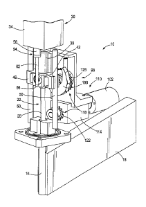
[0017] With reference to FIGS. 1-7, a gas spring fastener driver 10 for
driving fasteners
(e.g., nails, tacks, staples, etc.) into a workpiece is shown. The fastener
driver 10 includes a
main housing (not shown), a nosepiece 14 extending from the main housing, and
a magazine 18
for sequentially feeding collated fasteners into the nosepiece 14 prior to
each fastener-driving
operation. The fastener driver 10 also includes a drive blade 22, a tip 26 of
which is received
within the nosepiece 14, and an onboard gas spring mechanism 30 for driving
the drive blade 22
from an initial retracted position (shown in FIGS. 1 and 2) toward a driven
position coinciding
with ejection of a fastener from the nosepiece 14. Accordingly, the fastener
driver 10 does not
require an external source of air pressure or other external power source for
driving the drive
blade 22.
[0018] With reference to FIG. 1, the gas spring mechanism 30 includes a
cylinder
housing 34 in which a pressurized gas (e.g., air) is stored and a piston 38
protruding from the
cylinder housing 34. The pressurized gas biases the piston 38 toward a driven
position (shown in
FIGS. 3 and 4) in which it is fully extended from the cylinder housing 34. The
piston 38
includes a distal end 42 against which a head 46 of the drive blade 22 is
abuttable when the drive
blade 22 is in the retracted position (shown in FIGS. 1 and 2). Movement of
the drive blade 22 is
limited to axial reciprocation, between the retracted position and the driven
position, by parallel
guide rails 50 along which the head 46 of the drive blade 22 is slidable.
[0019] With reference to FIGS. 1-7, the fastener driver 10 also includes an
extensible
cylinder 54 for raising the drive blade 22 from the driven position toward the
retracted position.
In the illustrated embodiment of the fastener driver 10, the extensible
cylinder 54 includes a
cylinder housing 58 affixed to the main housing such that the cylinder housing
58 is stationary
3
CA 2969392 2017-06-02
relative to the main housing and the cylinder housing 34 of the gas spring
mechanism 30. The
cylinder housing 58 of the extensible cylinder 54 may be affixed directly to
the cylinder housing
34 of the gas spring mechanism 30, or directly to the main housing.
Alternatively, the cylinder
housing 58 of the extensible cylinder 54 may be affixed to an intermediate
component of the
fastener driver 10 which, either directly or indirectly, is affixed to the
main housing.
[0020] The extensible cylinder 54 also includes a rod 62 coupled to the
head 46 of the
drive blade 22 for movement with the drive blade 22. In the illustrated
embodiment of the
fastener driver 10, the rod 62 is abutted against a flange 66 (FIG. 1)
extending in a lateral
direction from a longitudinal axis 70 of the drive blade 22, and secured to
the flange 66 using a
fastener (e.g., a screw). Alternatively, the rod 62 may be affixed to the head
46 of the drive
blade 22 using a welding process, adhesives, an interference fit, or by
integrally forming, for
example. Accordingly, the rod 62 is axially movable between a retracted
positions coinciding
with the retracted positions of the piston 38 and the drive blade 22 (shown in
FIGS. 1 and 2), and
an extended position coinciding with the driven position of the drive blade 22
(not shown). A
longitudinal axis 74 of the extensible cylinder 54, therefore, is oriented
parallel with the
longitudinal axis 70 of the drive blade 22.
[0021] With reference to FIG. 8, the cylinder housing 58 of the extensible
cylinder 54
includes an interior chamber 78 in which the rod 62 is slidable. The rod 62
includes a piston 82
that divides the interior chamber 78 into a first variable volume region 86
and a second variable
volume region 90, the length of each of which is variable and dependent upon
the axial position
of the rod within the cylinder housing 58. The cylinder housing 58 includes an
aperture 94 at
one end thereof to fluidly communicate the first variable volume region 86
with an interior of the
main housing, which is exposed to atmospheric pressure. In the illustrated
embodiment of the
fastener driver 10, the aperture 94 is coaxial with the rod 62. Alternatively,
the aperture 94 may
be radially oriented relative to the longitudinal axis 74 of the extensible
cylinder 54. The rod 62
extends through the opposite end of the cylinder housing 58, with the second
variable volume
chamber 90 being exposed to the atmospheric pressure in the interior of the
main housing.
[0022] With continued reference to FIG. 8, the aperture 94 includes a
diameter D.
During a firing stroke of the drive blade 22 (to which the rod 62 is affixed),
the rod 62 is
4
CA 2969392 2017-06-02
accelerated quickly from its retracted position (shown in FIGS. 1, 2, and 8)
toward the extended
position, thereby expanding the volume of the first variable volume region 86
in a relatively
short time period. The diameter D of the aperture 94 is sized to restrict, but
not prohibit, the flow
of replacement air into the first variable volume region 86 during this period
of expansion.
Accordingly, a vacuum (i.e., an absolute pressure less than atmospheric
pressure) is created in
the first variable volume region 86 as the rod 62 is extended. Because the
second variable
volume region 90 is exposed to atmospheric pressure, no back-pressure is
exerted on the rod 62
during extension.
[0023] In another embodiment of the fastener driver 10, a one-way valve
(not shown)
may be substituted for the aperture 94 to prevent the flow of replacement air
into the first
variable volume region 86 during extension of the rod 62 relative to the
cylinder housing 58,
thereby creating a vacuum in the first variable volume region 86. When the rod
62 is retracted
into the cylinder housing 58 to the position shown in FIGS. 1 and 2, any
pressurized air within
the first variable volume region 86 (i.e., air pressurized above atmospheric
pressure) is
discharged through the aperture 94 and the one-way valve into the interior of
the main housing.
Such a one-way valve may be, for example, a ball check valve.
[0024] As is described in further detail below, between two consecutive
firing operations
of the fastener driver 10, the extensible cylinder 54 returns or raises the
drive blade 22 from the
driven position (coinciding with ejection of a fastener from the nosepiece 14)
to an intermediate
position (shown in FIGS. 5-7) between the driven position (not shown) and the
retracted position
(shown in FIGS. 1 and 2). The fastener driver 10 further includes a lifter
mechanism 98, shown
most clearly in FIGS. 2, 6, and 7, that completes the return of the drive
blade 22 by raising the
drive blade 22 from the intermediate position to the retracted position. In
the illustrated
embodiment of the fastener driver 10, the lifter mechanism 98 includes an
electric motor 102
powered by an on-board power source (e.g., a battery), a rotatable cam lobe
106, and a
transmission 110 interconnecting the motor 102 and the cam lobe 106. The
transmission 110
includes a planetary gear train 114 connected to an output shaft of the motor
102 and an offset
gear train 118 connected to the output of the planetary gear train 114.
Specifically, the offset
gear train 118 includes a small-diameter gear 122 connected with the output of
the planetary gear
train 114, a large-diameter gear 126 connected with the cam lobe 106, and a
chain (not shown)
CA 2969392 2017-06-02
intercoimecting the gears 122, 126. Accordingly, torque from the motor 102 is
transferred
through the planetary gear train 114 and the offset gear train 118, causing
the cam lobe to rotate
about a rotational axis 130 of the large-diameter gear 126 (FIG. 2).
100251 With reference to FIGS. 2, 6, and 7, the drive blade 22 includes a
follower 134
engaged with the cam lobe 106 while the drive blade 22 is raised from the
intermediate position
to the retracted position. In the illustrated embodiment of the fastener
driver 10, the follower 134
is configured as a cylindrical pin that is slidable along the outer periphery
of the cam lobe 106 in
response to rotation of the cam lobe 106. Alternatively, the follower 134 may
be supported
within the head 46 of the drive blade 22 by a bearing, thereby permitting the
follower 134 to
rotate relative to the head 46. With this arrangement, the follower 134, when
configured as a
cylindrical pin, may roll along the outer periphery of the cam lobe 106 in
response to rotation of
the cam lobe 106. Furthermore, the follower 134 protrudes from the head 46 of
the drive blade
22 in a lateral direction relative to the longitudinal axis70 of the drive
blade 22, and the cam lobe
106 is positioned between the drive blade 22 and the large-diameter gear 126
of the offset gear
train 118.
[0026] In operation of the fastener driver 10, a first firing operation is
commenced by the
user depressing a trigger (not shown) of the fastener driver 10. At this time,
the drive blade 22
and the piston 38 are held in their retracted positions, respectively, by the
cam lobe 106 (shown
in FIGS. 1 and 2). Shortly after the trigger being depressed, the motor 102 is
activated to rotate
the cam lobe 106 in a counter-clockwise direction about the rotational axis
130 from the frame of
reference of FIG. 2. Upon the follower 134 sliding off the tip of the cam lobe
106, the .
pressurized gas within the cylinder housing 34 expands, pushing the piston 38
outward from the
cylinder housing 34 and accelerating the drive blade 22 toward its driven
position. The cam lobe
106 is accelerated to a sufficient rotational speed to prohibit subsequent
contact with the follower
134 as the drive blade 22 is being driven from its retracted position to the
driven position. In
addition, the timing of the drive blade 22 reaching its intermediate position
coincides with the
follower 134 passing alongside a flat segment 138 of the cam lobe 106 (shown
most clearly in
FIG. 4), thereby creating an unobstructed path for the follower 134as the
drive blade 22 is
displaced from its intermediate position toward its driven position (not
shown).
6
CA 2969392 2017-06-02
[0027] After the piston 38 reaches its driven position (shown in FIGS. 3
and 4), the head
46 of the drive blade 22 separates from the distal end 42 of the piston 38
(coinciding with the
intermediate position of the drive blade 22), ceasing further acceleration of
the drive blade 22.
Thereafter, the drive blade 22 continues moving toward its driven position at
a relatively
constant velocity. Upon impact with a fastener in the nosepiece 14, the drive
blade 22 begins to
decelerate, ultimately being stopped after the fastener is driven into a
workpiece.
[0028] During the period of movement of the drive blade 22 from its
retracted position
(shown in FIGS. 1 and 2) to its driven position (not shown), because the rod
62 of the extensible
cylinder 54 is affixed to the head 46 of the drive blade 22 for movement
therewith, the rod 62 is
also pulled from the cylinder housing 58. As the rod 62 is pulled from the
cylinder housing 58, a
vacuum is created within the first variable volume region 86 because the rate
at which the
volume of the first variable volume region 86 expands exceeds the volumetric
flow rate of
replacement air drawn into the first variable volume region through the
aperture to "fill" the
expanded volume. After movement of the drive blade 22 is stopped following the
conclusion of
the first firing operation, a pressure imbalance acting on the rod piston 82
applies a force on the
rod 62, causing it to retract into the cylinder housing 58. Because the rod 62
is affixed to the
head 46 of the drive blade 22, the drive blade 22 is raised from its driven
position toward the
intermediate position. At this time, the rotation of the cam lobe 106 is
either momentarily
stopped or substantially slowed to allow the follower 134 to pass alongside
the flat segment 138
of the cam lobe 106 as the drive blade 22 approaches the intermediate
position.
[0029] Coinciding with the drive blade 22 reaching the intermediate
position, rotation of
the cam lobe 106 (in the same counter-clockwise direction) is resumed (or
alternatively
accelerated if previously slowed) to once again contact the follower 134
(shown in FIGS. 6 and
7). As the cam lobe 106 continues its rotation, the follower 134, the drive
blade 22, and the
piston 38 are displaced upward from the intermediate position of the drive
blade 22 shown in
FIGS. 5-8 toward the retracted position shown in FIGS. 1 and 2. At this time,
the rod 62 is also
retracted into the cylinder housing 58, purging air from the first variable
volume region 86 to the
interior of the main housing via the aperture 94. The cam lobe 106 continues
to raise the drive
blade 22 and the piston 38 until both reach their retracted positions shown in
FIGS. 1 and 2, at
7
CA 2969392 2017-06-02
which time the first firing operation is completed. Thereafter, additional
firing operations may
be initiated in a like manner.
[0030] In an alternative firing cycle, the lifter mechanism 98 may remain
deactivated
after the extensible cylinder 54 has returned the drive blade 22 to its
intermediate position,
thereby maintaining the piston 38 in its driven position shown in FIGS. 6 and
7, until the user
depresses the trigger to initiate a firing operation. This way, the gas spring
mechanism 30
remains in a deactivated state (i.e., with the piston 38 in its biased, driven
position) when the
fastener driver 10 is not in use.
[0031] By providing the extensible cylinder 54 to return the drive blade 22
partially
toward its retracted position following each fastener firing operation (i.e.,
as opposed to using the
lifter mechanism 98 to raise the drive blade 22 from its driven position to
its retracted position),
the cycle time between consecutive firing operations may be reduced, allowing
for more rapid
placement of fasteners into a workpiece.
[0032] With reference to FIGS. 9 and 10, another gas spring fastener driver
10a for
driving fasteners (e.g., nails, tacks, staples, etc.) into a workpiece is
shown, with like components
as the fastener driver 10 of FIGS. 1-8 being shown with like reference
numerals plus the letter
"a." Rather than including only a single extensible cylinder, the fastener
driver 10a includes two
extensible cylinders 54a, one positioned on each side of the gas spring
mechanism 30a. And, the
rods 62a of the respective extensible cylinders 54a are affixed to
corresponding flanges 66a on
the head 46a of the drive blade 22a.
[0033] With reference to FIG. 10, the lift mechanism 98a includes two cam
lobes 106a
coupled for synchronous co-rotation with respective large-diameter driven
gears 126a which, in
turn, receive torque from the motor 102a via a transmission 200. The follower
134a protrudes
from both the front and rear of the head 46a of the drive blade 22a, and is
engageable by both
cam lobes 106a for raising the drive blade 22a from its intermediate position
(as described
above) to its retracted position. Otherwise, the fastener driver 10a functions
identically to the
fastener driver 10 as described above.
[0034] Various features of the invention are set forth in the following
claims.
8
CA 2969392 2017-06-02