Note: Descriptions are shown in the official language in which they were submitted.
EXTERIOR-MATERIAL SECURING MEMBER AND BUILDING EXTERIOR
STRUCTURE
CROSS REFERENCES TO RELATED APPLICATIONS
This application is based on Japanese Patent
Application No. 2016-137748 filed in the Japanese Patent
Office on July 12, 2016, the entire contents of which are
hereby incorporated by reference.
BACKGROUND OF THE INVENTION
1. Field of the Invention
[0001] The present invention relates to an exterior-
material securing member and a building exterior structure.
2. Description of the Related Art
[0002] Examples of existing exterior-material securing
members are disclosed in Japanese Unexamined Patent
Application Publication No. 2006-265864 (Patent Document 1),
Japanese Unexamined Patent Application Publication No. 2005-
232710 (Patent Document 2), Japanese Unexamined Patent
Application Publication No. 10-148024 (Patent Document 3),
and Japanese Unexamined Patent Application Publication No.
2000-87529 (Patent Document 4). Each securing member
includes a fixing portion that is fixed to a framework and a
supporting portion that supports an exterior material.
[0003] Each securing member includes a first engagement
- 1 -
CA 2969434 2017-06-02
portion that is disposed on the supporting portion so as to
extend upward and engages with the exterior material, and a
second engagement portion that is disposed on the supporting
portion so as to extend downward and engages with the
exterior material.
[0004] Each securing member further includes a first
contact portion that is disposed above the supporting
portion and contacts a back surface of the exterior material,
and a second contact portion that is disposed below the
supporting portion and contacts the back surface of the
exterior material.
[0005] To be specific, in the securing member disclosed
in Patent Document 1, the supporting portion and the first
and second engagement portions are formed by cutting and
raising a part of the fixing portion, and an opening is
formed below the supporting portion.
[0006] In the securing member disclosed in Patent
Document 2, the supporting portion and the first and second
engagement portions are formed by bending a lower end
portion of the fixing portion. The first contact portion is
formed above the supporting portion of the fixing portion.
The second contact portion is formed by bending downward a
small part of the fixing portion located directly above the
supporting portion.
[0007] In the securing member disclosed in Patent
- 2 -
CA 2969434 2017-06-02
Document 3, as shown in Fig. 1 and other figures in Patent
Document 3, the supporting portion is formed by bending the
fixing portion at two positions (an upper position and a
lower position) so that two steel plates overlap. The first
engagement portion is formed in an upper one of the two
steel plates of the supporting portion. The second
engagement portion is formed in a lower one of the two steel
plates of the supporting portion. The first and second
contact portions are respectively formed in the upper steel
plate and the lower steel plate, which are two steel plates
of the supporting portion, or in only one of the two steel
plates of the supporting portion.
[0008] In the securing member disclosed in Patent
Document 4, the supporting portion, the first and second
engagement portions, and the first and second contact
portions are formed in a folded portion that is bent upward
in a U-shape from a lower part of the fixing portion.
[0009]
[0010] However, in the securing member disclosed in
Patent Document 1, the second contact portion is formed
below the supporting portion and below the opening.
Therefore, the securing member may not be able to stably
support an exterior material. Therefore, to stably support
the exterior material, it is necessary to use additional
means, such as integrating a contact portion of a side
- 3 -
CA 2969434 2017-06-02
surface of the opening with the second contact portion,
which is formed below the opening.
[0011] In the securing member disclosed in Patent
Document 2, the second contact portion is small, and
therefore the second contact portion contacts only a small
area of the back surface of the exterior material. As a
result, the securing member may not be able to stably
support an exterior material. Therefore, to stably support
the exterior material, it is necessary use additional means,
such as adjusting the thickness of the securing member from
a reference surface of the securing member to the second
contact portion.
[0012] In the securing member disclosed in Patent
Document 3, two steel plates of the support portion may
become deformed so as to be displaced from each other due to,
for example, a load or the like that is generated when the
supporting portion supports the exterior material. As a
result, the first and second engagement portions may become
displaced from each other. When the exterior material is
engaged with the first and second engagement portions that
have been displaced from each other, breakage or unevenness
of end portions of the exterior material occurs easily, and
the securing member may not be able to stably support the
exterior material. Moreover, in the securing member, the
thickness of the supporting portion is the sum of the
- 4 -
CA 2969434 2017-06-02
thicknesses of the two steel plates and the width of the gap
between the steel plates. Therefore, the distance between
exterior materials that are adjacent to each other with the
supporting portion therebetween increases, and trouble, such
as entry of rainwater, becomes more likely to occur.
[0013] In the securing member disclosed in Patent
Document 4, the supporting portion, the first and second
engagement portions, and the first and second contact
portions are formed in the U-shaped bent portion. Therefore,
it is difficult for the entirety of the securing member to
have a sufficient strength. Therefore, the securing member
may deform easily and may not be able to stably support the
exterior material.
SUMMARY OF THE INVENTION
[0014] The present invention, which has been devised
against the background described above, provides an
exterior-material securing member and a building exterior
structure that can stably support an exterior material by
preventing deformation of the securing member and can reduce
trouble of entry of rainwater from a gap between exterior
materials.
[0015] According to a first aspect of the present
invention, an exterior-material securing member, which is a
securing member for securing an exterior material to a
- 5 -
CA 2969434 2017-06-02
framework of a building, includes a fixing portion that is
fixed to the framework; a supporting portion that projects
from the fixing portion and supports the exterior material;
a first engagement portion that is disposed on the
supporting portion so as to extend in a first direction and
engages with the exterior material; a second engagement
portion that is disposed on the supporting portion so as to
extend in a second direction, which is opposite to the first
direction, and engages with the exterior material; a first
contact portion that is disposed in the first direction from
the supporting portion and contacts a back surface of the
exterior material; and a second contact portion that is
disposed in the second direction from the supporting portion
and contacts the back surface of the exterior material. The
second contact portion is formed in a folded portion that is
folded toward the supporting portion.
[0016] In the
exterior-material securing member according
to the first aspect, the supporting portion projects from
the fixing portion, and the first and second engagement
portions are disposed on the supporting portion. The second
contact portion is formed in the folded portion that is
folded toward the supporting portion. Therefore, with the
securing member, the degree of freedom in positioning the
second contact portion is increased. As a result, the
second contact portion can be easily disposed near the
- 6 -
CA 2969434 2017-06-02
supporting portion. AS necessary, the second contact
portion may be disposed on the center line of the securing
member.
[0017] With the securing member, the size of the folded
portion can be easily increased. Therefore, the size of the
second contact portion can also be increased. Moreover,
with the securing member, the folded portion can reinforce a
region around a part of the fixing portion adjacent to the
folded portion. Therefore, the entirety of the securing
member can easily have a sufficient strength.
[0018] As a result, the exterior-material securing member
according to the first aspect of the present invention can
stably support the exterior material by preventing
deformation thereof and can reduce trouble of entry of
rainwater from a gap between the exterior materials.
[0019] According to a second aspect of the present
invention, preferably, an end portion of the second contact
portion located in the first direction is disposed at a
position where the end portion is in contact with the
supporting portion or at a position where the end portion is
capable of contacting the supporting portion when the
supporting portion bends.
[0020] In this case, the second contact portion of the
folded portion can support the supporting portion. As a
result, it is possible to effectively reduce deformation of
- 7 -
CA 2969434 2017-06-02
the supporting portion due to a load or the like that is
generated when the securing member supports the exterior
material.
[0021] According to a third aspect of the present
invention, preferably, the folded portion is folded in the
first direction from an end portion of the fixing portion
located in the second direction.
[0022] In this case, compared with a case where the
folded portion is folded in a direction perpendicular to the
first and second directions, the folded portion and the
second contact portion can be easily formed. Moreover, the
second contact portion can be easily disposed on the center
line of the securing member. As a result, the securing
member can more stably support the exterior material.
[0023] According to a fourth aspect of the present
invention, preferably, the exterior-material securing member
further includes a bulging portion that is disposed in the
first direction from the supporting portion and bulges from
the fixing portion. In addition, preferably, the first
contact portion includes a first surface that is formed by a
front end surface of the bulging portion.
[0024] In this case, the bulging portion can increase the
strength of the first surface and the strength of the
entirety of the securing member. Moreover, the first
surface can be easily disposed on the center line of the
- 8 -
CA 2969434 2017-06-02
securing member. As a result, the securing member can more
stably support the exterior material.
[0025] According to a fifth aspect of the present
invention, preferably, the exterior-material securing member
further includes a pair of side plate portions that are
respectively formed by bending an end portion of the fixing
portion located in a third direction, which is substantially
perpendicular to the first direction, and an end portion of
the fixing portion located in a fourth direction, which is
opposite to the third direction.
[0026] In this case, the pair of side plate portions,
which are bent, can reinforce the fixing portion. Therefore,
the entirety of the securing member can more easily have a
sufficient strength. Moreover, because the pair of side
plate portions are disposed on both sides of the fixing
portion and cover the end surfaces of the fixing portion,
the appearance of the securing member is improved.
[0027] According to a sixth aspect of the present
invention, preferably, the first contact portion includes
second surfaces that are formed by front edges of the pair
of side plate portions.
[0028] In this case, the second surfaces are formed by
using the thicknesses of the side plate portions, which are
bent from the fixing portion, and can be used as a part of
the first contact portion.
- 9 -
CA 2969434 2017-06-02
[0029] According to a seventh aspect of the present
invention, preferably, the first contact portion includes
third surfaces that are formed by bending front end portions
of the pair of side plate portions in the third direction or
in the fourth direction.
[0030] In this case, the third surfaces, whose areas are
larger than those of the second surfaces and which are
formed by using the thicknesses of the side plate portions,
are formed by bending the front end portions of the side
plate portions; and the third surfaces can be used as a part
of the first contact portion.
[0031] According to an eighth aspect of the present
invention, preferably, front end portions of the pair of
side plate portions extend in a direction such that the
front end portions support the second contact portion at
positions in the second direction from the second contact
portion.
[0032] In this case, the front end portions of the pair
of side plate portions, which extend in a direction such
that the front end portions support the second contact
portion at positions in the second direction from the second
contact portion, can support the second contact portion, and
deformation of the second contact portion can be reduced.
As a result, the exterior material can be stably supported.
[0033] According to a ninth aspect of the present
- 10 -
CA 2969434 2017-06-02
invention, preferably, the exterior-material securing member
further includes an erected portion that is formed on at
least one of the second contact portion and a portion
located in the second direction from the second contact
portion and that is disposed between opposing end portions
of two exterior materials that are adjacent to each other.
[0034] In this case, the erected portion can prevent
displacement of the exterior material. Moreover, because
the degree of freedom in positioning the erected portion is
increased, the erected portion can be easily disposed near
the supporting portion.
[0035] According to a tenth aspect of the present
invention, a building exterior structure includes an
exterior material, a framework of a building, and a securing
member for securing the exterior material to the framework.
The securing member includes a fixing portion that is fixed
to the framework; a supporting portion that projects from
the fixing portion and supports the exterior material; a
first engagement portion that is disposed on the supporting
portion so as to extend in a first direction and engages
with the exterior material; a second engagement portion that
is disposed on the supporting portion so as to extend in a
second direction, which is opposite to the first direction,
and engages with the exterior material; a first contact
portion that is disposed in the first direction from the
- 11 -
CA 2969434 2017-06-02
supporting portion and contacts a back surface of the
exterior material; and a second contact portion that is
disposed in the second direction from the supporting portion
and contacts the back surface of the exterior material. The
second contact portion is formed in a folded portion that is
folded toward the supporting portion.
[0036] With the building exterior structure according to
the tenth aspect of the present invention, due to the
advantages effects of the securing member according to the
first aspect, the exterior material can be stably supported
by preventing deformation of the securing member, and
trouble of entry of rainwater from a gap between exterior
materials can be reduced.
[0037] With the exterior-material securing member and the
building exterior structure according to the present
invention, the exterior material can be stably supported by
preventing deformation of the securing member, and entry of
rainwater from a gap between exterior materials can be
reduced.
BRIEF DESCRIPTION OF THE DRAWINGS
[0038] Fig. 1 is a perspective view of a building
exterior structure according to a first embodiment;
Fig. 2 is a perspective view of an exterior wall plate
according to the first embodiment;
- 12 -
CA 2969434 2017-06-02
Fig. 3 is a partial perspective view illustrating the
structure in which exterior wall plates that are adjacent to
each other are assembled in the first embodiment;
Fig. 4 is a front view illustrating the positional
relationship between first to fourth exterior wall plates
and securing members according to the first embodiment;
Fig. 5 is a perspective view of the securing member
according to the first embodiment;
Fig. 6 is a front view of the securing member according
to the first embodiment;
Fig. 7 is a top view of the securing member according
to the first embodiment;
Fig. 8 is a side view of the securing member according
to the first embodiment;
Fig. 9 is a sectional view taken along IX-IX in Fig. 7;
Fig. 10 is a sectional view taken along X-X in Fig. 7;
Fig. 11 is a sectional view taken along XI-XI in Fig.
7;
Fig. 12 is a developed view of a steel plate before
being formed into the securing member according to the first
embodiment;
Fig. 13 is a partial perspective view illustrating a
method for positioning the securing member and the first and
third exterior wall plates according to the first
embodiment;
- 13 -
CA 2969434 2017-06-02
Fig. 14 is a partial perspective view illustrating the
structure in which the first and third exterior wall plates
are secured by using the securing member according to the
first embodiment;
Fig. 15 is a partial perspective view illustrating the
structure in which the first to third exterior wall plates
are secured by using the securing member according to the
first embodiment;
Fig. 16 is a partial sectional view taken along line
XVI-XVI in Fig. 14;
Fig. 17 is a partial sectional view taken along line
XVII-XVII in Fig. 16;
Fig. 18 is a perspective view of a securing member
according to a second embodiment;
Fig. 19 is a perspective view of a securing member
according to a third embodiment;
Fig. 20 is a perspective view of a securing member
according to a fourth embodiment; and
Fig. 21 is a perspective view of a securing member
according to a fifth embodiment.
DESCRIPTION OF THE PREFERRED EMBODIMENTS
[0039] Hereinafter, first to fifth embodiments of the
present invention will be described below with reference to
the drawings. In Fig. 1, "UP" denotes the vertically upward
- 14 -
CA 2969434 2017-06-02
direction, and "DOWN" denotes the vertically downward
direction. In addition, in Fig. 1, "LEFT" and "RIGHT"
respectively denote the horizontally leftward and rightward
directions when viewed in the direction from the exterior
side to the interior side. The directions in Fig. 2 and
other figures correspond to those in Fig. 1.
First Embodiment
[0040] Fig. 1 illustrates an exterior structure according
to a first embodiment. The exterior structure includes a
wooden framework 8 of a building, such as a house, a
facility, or a warehouse; and a plurality of exterior wall
plates 2 (shown in Figs. 2 to 4 and other figures) secured
to the wooden framework 8. The exterior wall plates 2 are
examples of "exterior material". The exterior wall plates 2
are plate materials that have high strength and rigidity and
constitute an exterior wall of a building. The exterior
materials are not limited to the exterior wall plates.
Alternatively, the exterior materials may be, for example,
decorative boards having a designed surface.
[0041] Referring to Fig. 1, in the present embodiment,
the framework 8 is constructed by timber framing. The
framework 8 is composed of a plurality of structural members.
The structural members include a plurality of columns 9 that
are arranged with predetermined intervals therebetween in
the horizontal direction and auxiliary members, such as
- 15 -
CA 2969434 2017-06-02
studs disposed between the columns 9. Support members 7,
which are called as furring strips, are fixed to the outer
surfaces of the columns 9 that face the exterior side with
fastening screws or nails (not shown). The support members
7 are also included in the structural members. A waterproof
sheet 6 is disposed between the columns 9 and the support
members 7. The structure of the framework 8 is not limited
to that in the present embodiment. Alternatively, the
framework 8 may be constructed by, for example, framing.
The framework of the exterior structure may be made of, for
example, steel, reinforced concrete, or brick.
[0042] Referring to Fig. 4, a plurality of securing
members 10 are fixed to the columns 9, which are structural
members, so that the exterior wall plates 2 are secured to
the framework 8 so as to be horizontally and vertically
adjacent to each other. The securing members 10 are
vertically arranged along each column 9.
[0043] Referring to Figs. 5 to 12, each of the securing
members 10 is formed by punching, pressing, and bending a
metal plate, such a steel plate or a stainless steel plate.
The material and the method of manufacturing the securing
member 10 are not limited to these, and various materials
and methods may be used as appropriate.
[0044] Referring to Figs. 13 to 17, the securing member
is fixed to each column 9 with screws 10B. However, this
- 16 -
CA 2969434 2017-06-02
is not a limitation. Alternatively, the securing member 10
may be fixed to, for example, the column 9 using other
fasteners, such as nails, or may be fixed indirectly to the
column 9 via the support member 7 (shown in Fig. 1) or the
like.
[0045] Referring to Figs. 4, 14, and other figures, the
standard orientation of the securing member 10 is the
orientation in a fixed state in which a fixing portion 15 of
the securing member 10 is fixed to the column 9. To be
specific, the front side of the securing member 10 faces the
exterior side, and the back side of the securing member 10
faces the interior side. The width direction of the
securing member 10 is the horizontal direction. In the
present embodiment, a first direction is the upward
direction. A second direction, which is opposite to the
first direction, is the downward direction. A third
direction, which is substantially perpendicular to the first
direction, is the leftward direction. A fourth direction,
which is opposite to the third direction, is the rightward
direction.
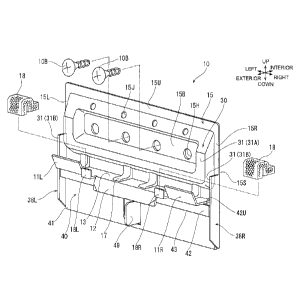
[0046] Referring to Figs. 5 to 11, the securing member 10
includes the fixing portion 15, a bulging portion 30, a
supporting portion 13, first engagement portions 11L and 11R,
a second engagement portion 12, a folded portion 40, a pair
of side plate portions 38L and 38R, a first contact portion
- 17 -
CA 2969434 2017-06-02
31, a second contact portion 42, and an erected portion 49.
[0047] Fig. 12 shows the shape of a steel plate, which is
the material of the securing member 10, before being pressed,
bent, and machined in other ways. The broken lines show
positions where the steel plate is to be mountain-folded.
The one-dot chain lines show portions where the steel plate
is to be valley-folded. The two-dot chain lines show
regions that will bulge when the steel plate is pressed.
[0048] Referring to Figs. 5 to 11, the fixing portion 15
is a flat plate-like portion that surrounds the bulging
portion 30, which is formed by pressing a metal plate, and
an opening 15M, which is formed at a position below the
bulging portion 30 as shown in Fig. 12 (developed view).
The opening 15M is formed by bending a part of the steel
plate inside a substantially U-shaped cutout portion 15C
(shown in Fig. 12) toward the front side. As shown by a
broken line in Fig. 6, the opening 15M has a substantially
rectangular shape.
[0049] An upper end portion 15U, a lower end portion 15D,
a left end portion 15L, and a right end portion 15R of the
fixing portion 15 form a peripheral edge portion. The
peripheral edge portion has a substantially rectangular
loop-like shape that is symmetrical about a center line Cl
extending in the vertical direction at the center of the
securing member 10 in the width direction. Referring to Fig.
- 18 -
CA 2969434 2017-06-02
8 and other figures, a surface of the securing member 10
that contacts the column 9 or the like and that faces the
back side is a reference surface 15S of the fixing portion
15.
[0050] Referring to Figs. 5 to 11, the bulging portion 30
bulges from the fixing portion 15 toward the front side in a
substantially rectangular loop shape. A surrounded portion
15B, which is surrounded by the bulging portion 30, is also
a part of the fixing portion 15. A plurality of fixing
holes 15H, which are arranged in the horizontal direction,
extend through the surrounded portion 15B. The screws 10B
are inserted into the fixing holes 15H to fix the securing
member 10 to the column 9 or the like. A plurality of
fixing holes 15J, which are arranged in the horizontal
direction, extend through an inclined surface at an upper
side of the bulging portion 30. The fixing holes 15J have a
diameter smaller than that of the fixing holes 15H.
Fasteners, such as screws or nails, for fixing the securing
member 10 to the column 9 or the like, are inserted into the
fixing holes 15J.
[0051] A front end surface of the bulging portion 30 at a
lower side, a left side, and a right side of the bulging
portion 30 forms a first surface 31A that extends parallel
to the reference surface 15S of the fixing portion 15. The
first surface 31A is a part of the first contact portion 31.
- 19 -
CA 2969434 2017-06-02
[0052] The supporting portion 13 is formed by bending a
plate-like portion that is located inside the cutout portion
15C shown in Fig. 12. Referring to Figs. 5 to 11, the
supporting portion 13 projects toward the front side from a
position that is adjacent to an upper side of the opening
15M of the fixing portion 15 and that is below the bulging
portion 30, and the supporting portion 13 extends in the
horizontal direction.
[0053] Referring to Figs. 5 to 9, the first engagement
portions 11L and 11R are respectively connected to a left
part and a right part of the front edge of the supporting
portion 13 and are bent upward. Referring to Figs. 5 to 8
and 10, the second engagement portion 12 is connected to a
central part of the front edge of the supporting portion 13
and is bent downward.
[0054] Referring to Figs. 5 to 11, a plurality of
projections 17, which are arranged in the horizontal
direction, are formed on the supporting portion 13. Each
projection 17 is a projection that projects upward from the
supporting portion 13 and that has a substantially
trapezoidal shape.
[0055] Holding portions 18L and 18R are disposed on the
supporting portion 13. The left holding portion 181 is a
small portion that is bent upward between the left first
engagement portion 11L and the second engagement portion 12.
- 20 -
CA 2969434 2017-06-02
The right holding portion 18R is a small portion that is
bent upward between the right first engagement portion 11R
and the second engagement portion 12.
[0056] Referring to Figs. 5 and 11, elastic members 18
are attached to the holding portions 18L and 18R using
double-sided adhesive tapes or the like. Referring to Fig.
11, the elastic members 18 respectively cover the holding
portions 181 and 18R and parts of the surface of the
supporting portion 13 facing upward, and the elastic members
18 are in contact with the fixing portion 15. Alternatively,
the elastic members 18 may be omitted.
[0057] The folded portion 40 includes a bent portion 41.
Referring to Fig. 12 (developed view), a substantially
rectangular plate-like portion, which is to become the
folded portion 40, is connected to the lower end portion 15D
of the fixing portion 15. The bent portion 41 is a
substantially U-shaped bent portion that is formed by
folding the substantially rectangular plate-like portion
upward from the lower end portion of 15D of the fixing
portion 15.
[0058] The folded portion 40 extends upward from the bent
portion 41 so as to become closer to the supporting portion
13 and extends in the horizontal direction.
[0059] A crank portion 43 and the second contact portion
42 are formed in an upper part of the folded portion 40.
- 21 -
CA 2969434 2017-06-02
The crank portion 43 is a portion that is bent toward the
front side of the securing member 10 at a position below the
supporting portion 13. The second contact portion 42 is a
portion that is bent upward from the crank portion 43. The
second contact portion 42 extends upward so as to become
closer to the supporting portion 13 and extends in the
horizontal direction. The front surface of the second
contact portion 42 extends parallel to the reference surface
15S. Referring to Fig. 6 and other figures, the width of
the second contact portion 42 is greater than the width of
the supporting portion 13.
[0060] Referring to Fig. 11, in the present embodiment,
the distance W1 between an upper end portion 42U of the
second contact portion 42 and the lower surface of the
supporting portion 13 is in the range of about 0.1 mm to 1
mm. To be specific, the distance W1 is set at a value that
allows the upper end portion 42U of the second contact
portion 42 to contact the lower surface of the supporting
portion 13 when the supporting portion 13 bends downward by
supporting the exterior wall plate 2. Thus, the second
contact portion 42 of the folded portion 40 reinforces the
supporting portion 13. Alternatively, the distance W1 may
be zero. In this case, the upper end portion 42U of the
second contact portion 42 is located at a position where the
upper end portion 42U is in contact with the lower surface
- 22 -
CA 2969434 2017-06-02
of the supporting portion 13.
[0061] Referring to Figs. 6, 8, and other figures, a part
of the folded portion 40 extending from the bent portion 41
to the crank portion 43 is adjacent to the peripheral edge
portion of the fixing portion 15 while covering a lower part
of the opening 15M. Thus, the folded portion 40 reinforces
a part of the fixing portion 15 around the opening 15M.
[0062] Referring to Figs. 5 to 8, the left side plate
portion 38L is formed by bending the left end portion 15L of
the fixing portion 15. The right side plate portion 38R is
formed by bending the right end portion 15R of the fixing
portion 15. The side plate portions 38L and 38R project
toward the front side of the securing member 10 and extend
in the vertical direction.
[0063] Portions of the front edges of the side plate
portions 38L and 38R located above the supporting portion 13
are second surfaces 31B, which extend parallel to the
reference surface 15S of the fixing portion 15. The second
surfaces 31B are substantially flush with the first surface
31A. The second surfaces 31B and the first surface 31A
constitute the first contact portion 31.
[0064] Portions of the front edges of the side plate
portions 38L and 38R located below the supporting portion 13
may be flush with the front surface of the second contact
portion 42. In this case, these portions and the second
- 23 -
CA 2969434 2017-06-02
contact portion 42 contact the back surface 2B of the
exterior wall plate 2.
[0065] The erected portion 49 is formed in a portion of
the securing member 10 located below the second contact
portion 42. To be specific, referring to Fig. 12, a
substantially C-shaped groove 49C is formed at a position
that is slightly to the left from the center of a part of
the folded portion 40 extending from the bent portion 41 to
the crank portion 43. The erected portion 49, which is
shown in Fig. 5 and other figures, is formed by cutting and
raising a plate-like portion inside the substantially C-
shaped groove 49C toward the front side of the securing
member 10. If the second contact portion 42 has a large
area in the second direction, the erected portion 49 may be
formed by cutting and raising a part of the second contact
portion 42.
[0066] Referring to Fig. 6, the erected portion 49 is
disposed at the center of the securing member 10 in the
width direction, that is, on the center line Cl.
[0067] Referring to Figs. 1, 2, 4, and other figures,
each exterior wall plate 2 is a quadrangular plate, to be
specific, a substantially rectangular plate that is
elongated in the horizontal direction. In the present
embodiment, the exterior wall plates 2 are made of a ceramic
material including cement. The material and shape of the
- 24 -
CA 2969434 2017-06-02
exterior wall plates 2 are not limited to those described
above. The material may be selected from metal materials,
wood materials, and resin materials as appropriate. The
shape may be selected from quadrangular shapes, such as a
substantially rectangular plate-like shape that is elongated
in the vertical direction, as appropriate.
[0068] Referring to Figs. 1, 4, 15, and other figures,
the exterior wall plates 2 are arranged horizontally and
vertically adjacent to each other and are disposed further
toward the exterior side of the framework 8 than the
waterproof sheet 6 and the support member 7. Thus, the
exterior wall plates 2 cover an exterior surface 8F of the
framework 8.
[0069] Referring to Figs. 2 and 3, the exterior wall
plate 2 has a front surface 2F, which is an exterior surface
having, for example, a brick pattern. A left end portion of
the exterior wall plate 2 includes a front horizontally
joining portion 21. A right end portion of the exterior
wall plate 2 includes a back horizontally joining portion 22.
A lower end portion of the exterior wall plate 2 includes a
front vertically joining portion 23. An upper end portion
of the exterior wall plate 2 includes a back vertically
joining portion 24.
[0070] In Fig. 2, the sizes of the front horizontally
joining portion 21, the back horizontally joining portion 22,
- 25 -
CA 2969434 2017-06-02
the front vertically joining portion 23, and the back
vertically joining portion 24 are exaggerated relative to
the size of the exterior wall plate 2.
(0071] The front horizontally joining portion 21 is
recessed stepwise from the back surface 2B toward the front
surface 2F of the exterior wall plate 2, and extends in the
vertical direction, that is, along the left end portion of
the exterior wall plate 2.
[0072] The back horizontally joining portion 22 is
recessed stepwise from the front surface 2F toward the back
surface 2B of the exterior wall plate 2, and extends in the
vertical direction, that is, along the right end portion of
the exterior wall plate 2. A caulking material 22S is
disposed on a flat surface of the back horizontally joining
portion 22 that faces the exterior side. The caulking
material 22S extends linearly along the back horizontally
joining portion 22. The caulking material is not essential,
and the caulking material 22S of the present embodiment may
be omitted.
[0073] The front vertically joining portion 23 is
recessed stepwise from the back surface 2B toward the front
surface 2F of the exterior wall plate 2, and extends in the
horizontal direction, that is, along the lower end portion
of the exterior wall plate 2. The front vertically joining
portion 23 includes an engagement recess 23A that is tapered
- 26 -
CA 2969434 2017-06-02
substantially upward.
[0074] The back vertically joining portion 24 is recessed
stepwise from the front surface 2F toward the back surface
2B of the exterior wall plate 2, and extends in the
horizontal direction, that is, along the upper end portion
of the exterior wall plate 2. A caulking material 24S is
disposed on a flat surface of the back vertically joining
portion 24 that faces the exterior side. The caulking
material 24S extends linearly along the back vertically
joining portion 24. The caulking material is not essential,
and the caulking material 24S of the present embodiment may
be omitted. The back vertically joining portion 24 includes
an engagement projection 24A that is located above the
caulking material 24S and that is tapered substantially
upward.
[0075] Referring to Figs. 4 and 13 to 16, a first shiplap
portion 26 is formed between horizontally adjacent exterior
wall plates 2 when the exterior wall plates 2 are placed so
that the front horizontally joining portion 21 of one of the
exterior wall plates 2 and the back horizontally joining
portion 22 of the other exterior wall plate 2 overlap each
other. Referring to Figs. 4, 15, and 17, a second shiplap
portion 25 is formed between vertically adjacent exterior
wall plates 2 when the exterior wall plates 2 are placed so
that the front vertically joining portion 23 of one of the
- 27 -
CA 2969434 2017-06-02
exterior wall plates 2 and the back vertically joining
portion 24 of the other exterior wall plate 2 overlap each
other.
[0076] That is, each exterior wall plate 2 has a so-
called "four-side shiplap structure" including the front
horizontally joining portion 21, the back horizontally
joining portion 22, the front vertically joining portion 23,
and the back vertically joining portion 24. The front
horizontally joining portion 21 of an exterior wall plate 2
and the back horizontally joining portion 22 of another
exterior wall plate 2 overlap each other to form the first
shiplap portion 26, and the front vertically joining portion
23 of an exterior wall plate 2 and the back vertically
joining portion 24 of another exterior wall plate 2 overlap
each other to form the second shiplap portion 25.
[0077] Referring to Fig. 4 and other figures, any one of
the exterior wall plates 2 is defined as a first exterior
wall plate 2A1, and three other exterior wall plates 2
having the following relationships with the first exterior
wall plate 2A1 are respectively defined as a second exterior
wall plate 2A2, a third exterior wall plate 2A3, and a
fourth exterior wall plate 2A4. The second exterior wall
plate 2A2 is adjacent to and above the first exterior wall
plate 2A1. The third exterior wall plate 2A3 is adjacent to
the first exterior wall plate 2A1 at the right side of the
- 28 -
CA 2969434 2017-06-02
first exterior wall plate 2A1. The fourth exterior wall
plate 2A4 is adjacent to and above the third exterior wall
plate 2A3 and is adjacent to the second exterior wall plate
2A2 at the right side of the second exterior wall plate 2A2.
[0078] The exterior wall plates 2 having the above-
described structure are supported by the securing members 10
in the following manner.
[0079] First, referring to Fig. 1, a plurality of
exterior wall plates 2 are attached to the bottom of the
exterior surface 8F of the framework 8 so as to be
horizontally adjacent to each other. At this time, the
lower end portions of the exterior wall plates 2 are engaged
with a bottom support member 55 disposed at the bottom of
the exterior surface 8F of the framework 8 so as to extend
in the horizontal direction. Here, two of the exterior wall
plates 2 that are horizontally adjacent to each other will
be referred to as the first exterior wall plate 2A1 and the
third exterior wall plate 2A3.
[0080] Next, referring to Fig. 13, the securing member 10
is moved downward while the reference surface 15S thereof is
in contact with the column 9, and the erected portion 49 of
the securing member 10 is inserted into the first shiplap
portion 26 of the first and third exterior wall plates 2A1
and 2A3 from above. Then, referring to Figs. 14 and 16, the
screws 10B are inserted through the fixing holes 15H and
- 29 -
CA 2969434 2017-06-02
screwed into the column 9, so that the securing member 10 is
fixed to the column 9.
[0081] Thus, the engagement projections 24A of the back
vertically joining portions 24 of the first and third
exterior wall plates 2A1 and 2A3 are retained by the second
engagement portion 12 of the securing member 10. In
addition, the second contact portion 42 of the securing
member 10 contacts the back surfaces 2B of the first and
third exterior wall plates 2A1 and 2A3. Thus, the first and
third exterior wall plates 2A1 and 2A3 are prevented from
being displaced toward the interior side. As a result,
referring to Figs. 16 and 17, a ventilation space Si is
formed between the framework 8 and the back surfaces 2B of
the first and third exterior wall plates 2A1 and 2A3.
[0082] Thus, the securing member 10 supports the upper
end portions of the first and third exterior wall plates 2A1
and 2A3 in the fixed state. In the fixed state, the erected
portion 49 of the securing member 10 is disposed between the
end portions of the first and third exterior wall plates 2A1
and 2A3 that oppose each other in the horizontal direction,
thereby preventing sideways displacement of the first and
third exterior wall plates 2A1 and 2A3.
[0083] Next, referring to Figs. 15 and 17, the second and
fourth exterior wall plates 2A2 and 2A4 are attached to
positions above the first and third exterior wall plates 2A1
- 30 -
CA 2969434 2017-06-02
and 2A3 so as to be horizontally adjacent to each other.
[0084] Thus, the engagement recesses 23A of the front
vertically joining portions 23 of the second and fourth
exterior wall plates 2A2 and 2A4 are engaged with the first
engagement portions 11L and 11R of the securing member 10.
[0085] At this time, referring to Figs. 9 and 10, the
projections 17 on the supporting portion 13 contact lower
end portions of the second and fourth exterior wall plates
2A2 and 2A4 from below, and thereby the supporting portion
13 supports the second and fourth exterior wall plates 2A2
and 2A4.
[0086] Referring to Fig. 17, one of the elastic members
18 that is adjacent to the left first engagement portion 11L
contacts the lower end of the second exterior wall plate 2A2
and becomes compressed and deformed. Although not
illustrated, the other elastic member 18 that is adjacent to
the right first engagement portion 11R also contacts the
lower end of the fourth exterior wall plate 2A4 and becomes
compressed and deformed. The elastic members 18 on the left
and right sides respectively seal the space between the
second exterior wall plate 2A2 and the supporting portion 13
and the space between the fourth exterior wall plate 2A4 and
the supporting portion 13.
[0087] The first contact portion 31 of the securing
member 10, to be specific, the first surface 31A of the
- 31 -
CA 2969434 2017-06-02
bulging portion 30 and the second surfaces 31B of the side
plate portions 38L and 38R contact the back surfaces 2B of
the second and fourth exterior wall plates 2A2 and 2A4.
Thus, the second and fourth exterior wall plates 2A2 and 2A4
are prevented from being displaced toward the interior side.
As a result, a ventilation space Si is also formed between
the framework 8 and the back surfaces 2B of the second and
fourth exterior wall plates 2A2 and 2A4.
[0088] Thus, the securing member 10 supports the second
and fourth exterior wall plates 2A2 and 2A4 in the fixed
state. Although not illustrated, the upper end portions of
the second and fourth exterior wall plates 2A2 and 2A4 are
supported on, for example, the column 9 by another securing
member 10 in the above-described manner. The above-
described operation is performed on other exterior wall
plates 2 so that the exterior wall plates 2 are supported on,
for example, the columns 9 while being horizontally and
vertically adjacent to each other. Thus, the exterior wall
plates 2 cover the exterior surface 8F of the framework 8.
[0089] Referring to Fig. 4, an additional securing member
may be disposed between any two securing members 10 that are
arranged horizontally adjacent to each other. In this case,
the exterior wall plates 2 that are vertically adjacent to
each other can be more securely supported.
Advantageous Effects
- 32 -
CA 2969434 2017-06-02
[0090] Referring to Figs. 5 to 10 and other figures, in
the securing member 10 according to the first embodiment,
the supporting portion 13 projects from the fixing portion
15, and the first engagement portions 11L and 11R and the
second engagement portion 12 are disposed on the front edge
of the supporting portion 13. The second contact portion 42
is formed in the folded portion 40 that is folded toward the
supporting portion 13. Therefore, with the securing member
10, compared with a hypothetical case where the second
contact portion 42 is formed on the fixing portion 15, the
degree of freedom in positioning the second contact portion
42 is increased. As a result, the second contact portion 42
can be easily disposed near the supporting portion 13. As
necessary, the second contact portion 42 may be disposed on
the center line Cl of the securing member 10.
[0091] Referring to Figs. 5, 6, and other figures, with
the securing member 10, the size of the folded portion 40
can also be easily increased. Therefore, the size of the
second contact portion 42 can also be increased. Moreover,
with the securing member 10, the folded portion 40 can
reinforce a region around a part of the fixing portion 15
adjacent to the folded portion 40. To be specific,
referring to Figs. 5, 6, 8, and other figures, a part of the
folded portion 40 extending from the bent portion 41 to the
crank portion 43 is adjacent to the peripheral edge portion
- 33 -
CA 2969434 2017-06-02
of the fixing portion 15 while covering a lower part of the
opening 15M. Thus, the folded portion 40 reinforces a part
of the fixing portion 15 around the opening 15M. Therefore,
the entirety of the securing member 10 can easily have a
sufficient strength.
[0092] As a result, the securing member 10 and the
exterior structure according to the first embodiment can
stably support the exterior wall plate 2 by preventing
deformation of the securing member 10 and can reduce trouble
of entry of rainwater from a gap between the exterior wall
plates 2.
[0093] Referring to Figs. 11 and 17, in the securing
member 10, the distance W1 between the upper end portion 42U
of the second contact portion 42 and the lower surface of
the supporting portion 13 is in the range of about 0.1 mm to
1 mm. Therefore, the upper end portion 42U of the second
contact portion 42 is disposed at a position where the upper
end portion 42U is capable of contacting the lower surface
of the supporting portion 13 when the supporting portion 13
bends downward by supporting the exterior wall plate 2.
Alternatively, the distance W1 may be zero, so that the
upper end portion 42U of the second contact portion 42 is
located at a position where the upper end portion 42U is in
contact with the lower surface of the supporting portion 13.
Thus, the second contact portion 42 of the folded portion 40
- 34 -
CA 2969434 2017-06-02
can support the supporting portion 13. As a result, with
the securing member 10, it is possible to effectively reduce
deformation of the supporting portion 13 due to a load or
the like that is generated when the securing member 10
supports the exterior wall plate 2.
[0094] Referring to Fig. 5 and other figures, with the
securing member 10, the folded portion 40 includes the bent
portion 41, which is folded upward from the lower end
portion of 15D of the fixing portion 15. Thus, with the
securing member 10, compared with a hypothetical case where
the folded portion 40 is folded rightward from the left end
portion 15L of the fixing portion 15 or the folded portion
40 is folded leftward from the right end portion 15R of the
fixing portion 15, a part of the fixing portion 15
surrounding the opening 15M can be easily reinforced and the
second contact portion 42 can be easily formed. Moreover,
the second contact portion 42 can be easily disposed on the
center line Cl of the securing member 10. As a result, the
securing member 10 can more stably support the exterior wall
plate 2.
[0095] Referring to Fig. 5 and other figures, in the
securing member 10, the front end surface of the bulging
portion 30, which is formed by pressing, forms the first
surface 31A of the first contact portion 31. Therefore, the
strength of the first surface 31A can be increased, and the
- 35 -
CA 2969434 2017-06-02
strength of the entirety of the securing member 10 can be
increased. Moreover, because the first surface 31A can be
easily disposed on the center line Cl of the securing member
10, the back surface 2B of the exterior wall plate 2 can be
evenly supported, and the securing member 10 can more stably
support the exterior wall plate 2.
[0096] Referring to Fig. 5 and other figures, in the
securing member 10, the pair of side plate portions 38L and
38R, which are formed by bending the left end portion 15L
and the right end portion 15R of the fixing portion 15, can
reinforce the fixing portion 15. Therefore, the entirety of
the securing member 10 can more easily have a sufficient
strength. Moreover, because the side plate portions 38L and
38R are disposed on both sides of the fixing portion 15 and
cover the end surfaces of the fixing portion 15, the
appearance of the securing member 10 is improved.
[0097] Referring to Fig. 5 and other figures, in the
securing member 10, the second surfaces 31B of the first
contact portion 31 are formed at the front edges of the side
plate portions 38L and 38R. That is, the second surfaces
31B are formed by using the thicknesses of the side plate
portions 38L and 38R, which are steel plates bent from the
fixing portion 15, and the second surfaces 31B are used as a
part the first contact portion 31. Therefore, the
manufacturing process can be simplified.
- 36 -
CA 2969434 2017-06-02
[0098] Referring to Figs. 5, 13, and 17, in the securing
member 10, the erected portion 49, which is formed in the
folded portion 40, can prevent displacement of the exterior
wall plate 2. Moreover, compared with a hypothetical case
where the erected portion 49 is formed on the fixing portion
15, the degree of freedom in positioning the erected portion
49 is increased. Therefore, the erected portion 49 can be
easily disposed near the supporting portion 13.
Second Embodiment
[0099] Fig. 18 illustrates a securing member 210
according to a second embodiment. The securing member 210
includes a bulging portion 230A, a bulging portion 230B, and
a plurality of bulging portions 2300, instead of the bulging
portion 30 of the securing member 10 according to the first
embodiment. In the securing member 210, a front end portion
of the left side plate portion 38L is bent leftward, and a
front end portion of the right side plate portion 38R is
bent rightward. The securing member 210 includes a first
contact portion 231, instead of the first contact portion 31
according to the first embodiment. The securing member 210
does not include the erected portion 49 according to the
first embodiment. Other elements of the second embodiment
are the same as those of the first embodiment. Therefore,
elements that are the same as those of the first embodiment
will be denoted by the same numerals, and descriptions of
- 37 -
CA 2969434 2017-06-02
such elements will be omitted or simplified.
[0100] The bulging portion 230A bulges from the fixing
portion 15 toward the front side at a position above the
supporting portion 13 and extends in the horizontal
direction. The bulging portion 230B bulges from the fixing
portion 15 toward the front side at a position above the
bulging portion 230A and extends in the horizontal direction.
The bulging portions 230C are formed between the bulging
portion 230A and the bulging portion 230B. Each bulging
portion 230C bulges from the fixing portion 15 toward the
front side, extends in the vertical direction, and is
connected to the bulging portions 230A and 230B.
[0101] A front end surface of the bulging portion 230A is
a first surface 231A that extends parallel to the reference
surface 15S of the fixing portion 15. The first surface
231A is a part of the first contact portion 231.
[0102] Third surfaces 231C, which extend parallel to the
reference surface 15S of the fixing portion 15, are formed
by a surface of a front end portion of the left side plate
portion 38L that is bent leftward and that is located above
the supporting portion 13 and a surface of a front end
portion of the right side plate portion 38R that is bent
rightward and that is located above the supporting portion
13. The third surfaces 231C are substantially flush with
the first surface 231A. The third surfaces 231C and the
- 38 -
CA 2969434 2017-06-02
first surface 231A constitute the first contact portion 231.
[0103] A front surface of a front end portion of the left
side plate portion 38L that is bent leftward and that is
located below the supporting portion 13 and a front surface
of a front end portion of the right side plate portion 38R
that is bent rightward and that is located below the
supporting portion 13 may be substantially flush with the
front surface of the second contact portion 42 and may
contact the back surface 2B of the exterior wall plate 2
together with the second contact portion 42.
[0104] The securing member 210 and the exterior structure
according to the second embodiment, having the above-
described structure, can stably support the exterior wall
plate 2 by preventing deformation of the securing member 210
and can reduce trouble of entry of rainwater from a gap
between exterior wall plates 2 in the same way as the
securing member 10 according to the first embodiment.
[0105] Moreover, with the securing member 210, the third
surfaces 231C, which are formed by bending the front end
portions of the side plate portions 38L and 38R, have a
larger area than the second surfaces 31B according to the
first embodiment, which are formed by using the thicknesses
of the steel plates of the side plate portions 38L and 38R,
and the third surfaces 231C can be used as a part of the
first contact portion 231. As a result, the first contact
- 39 -
CA 2969434 2017-06-02
portion 231 can more effectively support the back surface 2B
of the exterior wall plate 2.
Third Embodiment
[0106] Fig. 19 illustrates a securing member 310
according to a third embodiment. The securing member 310
includes supporting portions 337L and 337R, which are formed
in front end portions of the side plate portions 38L and 38R
of the securing member 10 according to the first embodiment.
Other elements of the third embodiment are the same as those
of the first embodiment. Therefore, elements that are the
same as those of the first embodiment will be denoted by the
same numerals, and descriptions of such elements will be
omitted or simplified.
[0107] The supporting portion 337L is formed by bending
rightward a front end portion of the left side plate portion
38L located below the second contact portion 42 so as to
extend in such a direction that the front end portion
supports the second contact portion 42. The supporting
portion 337R is formed by bending leftward a front end
portion of the right side plate portion 38R located below
the second contact portion 42 so as to extend in such a
direction that the front end portion supports the second
contact portion 42.
[0108] An upper end portion 337LU of the left supporting
portion 3371 and an upper end portion 337RU of the right
- 40 -
CA 2969434 2017-06-02
supporting portion 337R are located at positions where the
upper end portions 337LU and 337RU are in contact with the
crank portion 43 of the folded portion 40; or the upper end
portion 337LU of the left supporting portion 337L and the
upper end portion 337RU of the right supporting portion 337R
are located at positions, at a distance in the range of
about 0.1 mm to 1 mm from the crank portion 43, where the
upper end portion 337LU and 337RU are capable of contacting
the crank portion 43 when the crank portion 43 bends by
supporting the exterior wall plate 2.
[0109] The securing member 310 and the exterior structure
according to the third embodiment, having the above-
described structure, can stably support the exterior wall
plate 2 by preventing deformation of the securing member 310
and can reduce trouble of entry of rainwater from a gap
between exterior wall plates 2 in the same way as the
securing members 10 and 210 according to the first and
second embodiments.
[0110] Moreover, with the securing member 310, the
supporting portions 337L and 337R can support the second
contact portion 42 via the crank portion 43 and can reduce
deformation of the second contact portion 42. As a result,
the second contact portion 42 can more effectively support
the back surface 2B of the exterior wall plate 2.
Fourth Embodiment
- 41 -
CA 2969434 2017-06-02
[0111] Fig. 20 illustrates a securing member 410
according to a fourth embodiment. The securing member 410
does not include the folded portion 40, the second contact
portion 42, and the erected portion 49 of the securing
member 10 according to the first embodiment. Instead, the
securing member 410 includes second contact portions 442L
and 442R that are formed in front end portions of the side
plate portions 38L and 38R. Other elements of the fourth
embodiment are the same as those of the first embodiment.
Therefore, elements that are the same as those of the first
embodiment will be denoted by the same numerals, and
descriptions of such elements will be omitted or simplified.
[0112] The second contact portion 442L is formed by
bending rightward a front end portion of the left side plate
portion 38L located below the supporting portion 13 so as to
extend in such a direction that the front end portion
supports the supporting portion 13. The second contact
portion 442R is formed by bending leftward a front end
portion of the right side plate portion 38R located below
the supporting portion 13 so as to extend in such a
direction that the front end portion supports the supporting
portion 13. A right end portion of the left second contact
portion 442L and a left end portion of the right second
contact portion 442R oppose each other at the center of the
securing member 410 in the width direction. Front surfaces
- 42 -
CA 2969434 2017-06-02
of the second contact portions 442L and 442R extend parallel
to the reference surface 15S and are capable of contacting
the back surface 2B of the exterior wall plate 2. Although
not illustrated, an erected portion 49 may be formed by
extending one of opposing end portions of the second contact
portions 442L and 442R by a length over which the erected
portion 49 is to project and by bending the end portion at a
central portion.
[0113] An upper end portion 442LU of the left second
contact portion 442L and an upper end portion 442RU of the
right second contact portion 442R are located at positions
where the upper end portions 442LU and 442RU are in contact
with the lower surface of the supporting portion 13; or the
upper end portion 442LU of the left second contact portion
442L and the upper end portion 442RU of the right second
contact portion 442R are located at positions, at a distance
in the range of about 0.1 mm to 1 mm from the lower surface
of the supporting portion 13, where the upper end portions
442LU and 442RU are capable of contacting the lower surface
of the supporting portion 13 when the supporting portion 13
bends by supporting the exterior wall plate 2. Thus, the
upper end portions 442LU and 442R0 support the supporting
portion 13.
[0114] The securing member 410 and the exterior structure
according to the fourth embodiment, having the above-
- 43 -
CA 2969434 2017-06-02
described structure, can stably support the exterior wall
plate 2 by preventing deformation of the securing member 410
and can reduce trouble of entry of rainwater from a gap
between exterior wall plates 2 in the same way as the
securing members 10, 210, and 310 according to the first to
third embodiments.
Fifth Embodiment
[0115] Fig. 21 illustrates a securing member 510
according to a fifth embodiment. The securing member 510
does not include the folded portion 40, the second contact
portion 42, and the erected portion 49 of the securing
member 10 according to the first embodiment. Instead, the
securing member 510 includes a second contact portion 542
that is formed in a front end portion of the left side plate
portion 38L. Other elements of the fifth embodiment are the
same as those of the first embodiment. Therefore, elements
that are the same as those of the first embodiment will be
denoted by the same numerals, and descriptions of such
elements will be omitted or simplified. Although not
illustrated, an erected portion 49 may be formed by cutting
and raising a part of the second contact portion 542.
[0116] The second contact portion 542 is formed by
bending rightward a front end portion of the left side plate
portion 38L located below the supporting portion 13 so as to
extend toward the supporting portion 13. A right end
- 44 -
CA 2969434 2017-06-02
portion of the second contact portion 542 is located near
the right side plate portion 38R. The front surface of the
second contact portion 542 extends parallel to the reference
surface 15S and is capable of contacting the back surface 2B
of the exterior wall plate 2.
[0117] An upper end portion 542U of the second contact
portion 542 is located at a position where the upper end
portion 542U is in contact with the lower surface of the
supporting portion 13; or the upper end portion 542U of the
second contact portion 542 is located at a position, at a
distance in the range of about 0.1 mm to 1 mm from the lower
surface of the supporting portion 13, where the upper end
portion 542U is capable of contacting the lower surface of
the supporting portion 13 when the supporting portion 13
bends by supporting the exterior wall plate 2. Thus, the
upper end portion 542U supports the supporting portion 13.
[0118] The securing member 510 and the exterior structure
according to the fifth embodiment, having the above-
described structure, can stably support the exterior wall
plate 2 by preventing deformation of the securing member 510
and can reduce trouble of entry of rainwater from a gap
between exterior wall plates 2 in the same way as the
securing members 10, 210, 310, and 410 according to the
first to fourth embodiments.
Sixth Embodiment
- 45 -
CA 2969434 2017-06-02
[0119] In the first to fifth embodiments described above,
the supporting portion 13 is integrated with the first
engagement portions 11L and 11R and the second engagement
portion 12. However, this is not a limitation. Although
not illustrated, a part of the supporting portion 13 to
which the first engagement portion 11L is connected, a part
of the supporting portion 13 to which the second engagement
portion 12 is connected, and a part of the supporting
portion 13 to which the first engagement portion 11R is
connected may be separated from each other. In this case,
rainwater on the supporting portion 13 flows downward
through gaps between the parts of the supporting portion 13,
which are separated from each other and which are connected
to the first engagement portions 11L and 11R and the second
engagement portion 12. Therefore, the rainwater is
prevented from spreading in the width direction along the
supporting portion 13.
[0120] The present invention is not limited to the first
to sixth embodiments described above. The present invention
can be applied to any appropriate embodiments within the
spirit and scope thereof.
[0121] In the first embodiment, the erected portion 49 is
formed in a part of the folded portion 40 located below the
second contact portion 42. However, this is not a
limitation. For example, the erected portion 49 may be
- 46 -
CA 2969434 2017-06-02
formed by cutting and raising a part of the second contact
portion 42, or may be formed in the second contact portion
42 and in a portion located below the second contact portion
42.
[0122] In the first embodiment, the first direction is
the upward direction, the second direction is the downward
direction, the first engagement portions 11L and 11R extend
upward, and the second engagement portion 12 extends
downward. However, this is not a limitation. For example,
the first direction may be the downward direction, the
second direction may be the upward direction, the first
engagement portions may extend downward, and the second
engagement portion may extend upward.
- 47 -
CA 2969434 2017-06-02