Note: Descriptions are shown in the official language in which they were submitted.
Unbacked and Modifiable Tapes and Skin Dressings
CROSS-REFERENCE TO RELATED APPLICATION
[001] This application claims priority to U.S. Provisional Application
Nos.:
62/090,350 filed 10 December 2014; 62/090,437 filed 11 December 2014; and
62/182,417
filed 19 June 2015 by the present inventor.
FIELD OF THE INVENTION
[002] This invention relates to tapes and dressings intended to provide a
fluid-
impervious barrier over skin, including dressings suitable for negative
pressure wound
therapy.
BACKGROUND OF THE INVENTION
[003j Negative pressure wound therapy ("NPWT") is an effective
technology for
treating open wounds. NPWT devices were originally accepted by the U.S. Food
and Drug
Administration ("FDA") in 1995, when the FDA approved a 510(K) for the Kinetic
Concepts Inc. ("KCI")'s V.A.C.0 device. The defutition of NPWT devices by the
FDA has
changed over the years; in general terms, its definition is: a system that is
used to apply
negative pressure for wound management purposes, including the removal of
fluids (i.e.,
wound exudates, irrigation fluids, and infectious materials). The negative
pressure is applied
through a porous dressing positioned into or over the wound cavity, depending
on wound
type and depth, or over a flap or graft; the dressing distributes the pressure
while removing
fluids from the wound. NWPT systems typically include:
= Non-adhesive wound dressing used to fill the wound cavity (e.g., a
sterilized
medical sponge or gauze; a.k.a., non-adhesive packing materials);
= Drainage tube placed adjacent to or into the dressing;
= Occlusive transparent film placed over the dressing (and potentially the
drainage
tube) and adhered to the skin to maintain a seal;
= Collection container for drained fluids from the wound; and
= Low pressure vacuum source.
[004] NPWT has been approved by the FDA to treat many wound types:
chronic,
acute, traumatic, sub-acute and dehisced wounds, partial-thickness burns,
ulcers (such as
diabetic, venous or pressure), surgically closed incisions (a.k.a., closed
surgical incisions),
- 1 -
Date Recue/Date Received 2022-07-04
CA 02969472 2017-05-31
WO 2016/094742
PCT/US2015/065132
flaps and grafts. The prescribed therapy time depends on wound type, wound
dimensions,
and patient conditions; it typically lasts from four weeks to four months.
Disposable dressing
components are changed approximately every three days.
[005]
Extensive clinical trials have demonstrated the success of negative pressure
in
healing the approved wound types by applying a controlled negative pressure
typically
between 20mmHg and 200mmHg. Most studies applied a constant vacuum pressure,
with
125mmHg being the most common, although cyclic and intermittent studies have
also
shown positive results. Evidence supporting the use of NPWT in the treatment
of chronic,
non-healing wounds exists primarily in the form of nonrandomized, controlled
trials;
prospective and retrospective large and small case series; single-center
studies; and single
case studies, with few randomized, controlled clinical trials. Studies also
exist that
demonstrate NPWT benefits in healing acute wounds. Additionally, since 2006,
benefits of
managing surgical incisions post-operatively have been shown with improved
clinical
outcomes; at least ten studies have been published to date. From these
studies, proven
medical benefits of NPWT treatment include:
= Promotes blood flow (perfusion) at the wound;
= Removes interstitial fluid (a.k.a., wound exudates), reduces edema;
= Decreases counts of bacteria and infectious materials;
= Increases rate of granulation tissue formation, reducing scar tissue
formation;
= Increases growth factors and fibroblasts;
= Uniformly draws the wound edges together;
= Provides a protected healing environment; and
= Provides a moist environment.
[006]
Although significant clinical evidence exists to support the benefit of NPWT
as a safe therapy in healing chronic wounds, it is possible during NPWT to
rupture a vein or
artery. Usually, a machine safety alarm will signify a fluid leak rate that
exceeds the rate that
the machine was designed for. This alarmed leak rate typically includes the
combination of
both air and liquid, and typically has an upper safety limit of the minimum
blood flow rate
possible out of a wound cavity with an actively bleeding vein or artery. If a
vein or artery
accidently ruptures, the system must shut down. Therefore, it is very
important to have a
safety feature that stops negative pressure if this occurs, in order not to
actively exsanguinate
the patient.
- 2 -
CA 02969472 2017-05-31
WO 2016/094742
PCT/US2015/065132
[007] Lina et al. describe in U.S. Patent No. 7,611,500 and W01996/005873
an
initial apparatus used for NPWT. In practice, the device proved to be
effective; however,
one major limitation was detected: the high electrical grid power source
needed to operate
the device limited the mobility of a patient. Therefore, future refinements,
such as that
described by Hunt et al. in U.S. Patent No. 6,142,982, incorporated
rechargeable batteries
for the power source. Batteries increased patient mobility, but time was
limited by the life
of the batteries between charges. Additionally, battery management became an
issue,
especially for facilities with a high number of NPWT patients, and electrical
grid power was
still needed to recharge the batteries.
[008] Eliminating the need for electrical power, via the grid or batteries,
would
create a more widely applicable, clinically viable therapy. The power
requirement variability
of a system is dependent on the desired vacuum pressure, rate of wound exudate
removal
from the wound cavity, and the leak rate of air into the system. As the air
leak rate increases,
more power is needed to supply a continuous negative pressure at a
predetermined value or
threshold range at the wound bed. Air leakage into the NPWT system requires
the most
power of any other component. Air leaks are the obstacle to creating a vacuum
system that
does not require a continuous external power source or frequent recharging of
its internal
power storage. Therefore, the feasibility of a mechanical NPWT system is
heavily reliant on
the seal quality of every interface in the system. The dressing system has
been identified as
the main source of air leaks in current NPWT systems, particularly at the
interfaces between
1) the dressing and the skin and 2) the tube and the dressing. The amount of
air leaks into
these interfaces determines the time frequency that the pump needs to be
recharged and the
magnitude of vacuum pressure applied to the wound cavity at a specific time.
These two
latter characteristics are dependent system parameters.
[009] Few mechanical NPWT systems are currently available, as described by
the
present inventor in "Development of a simplified Negative Pressure Wound
Device"
submitted in 2007 for her Master of Science in Mechanical Engineering at the
Massachusetts
Institute of Technology. Certain lower-pressure, mechanical devices were
disclosed later by
Hu et al. in U.S. Patent Application No. 2010/0228205. Current mechanical
systems
typically use sophisticated-material, planar dressings, such as hydrocolloid
dressings, to try
to solve the air leak problem. However, the inherent geometry mismatch of a
planar dressing
and the contoured skin surface often leads to air leaks. The mechanical
devices therefore are
- 3 -
CA 02969472 2017-05-31
WO 2016/094742
PCT/US2015/065132
only applicable for select, relatively flat surfaces on the body and, even
then, it is difficult to
eliminate air leaks entirely.
[010] Non-electrical pumps are at the low end of the spectrum of medical
pumps,
typically utilizing bladder pumps and capillary action materials. Bladder
pumps are used for
both extracting and inserting fluids. By their physical characteristics, they
are governed by
non-linear spring like properties. Currently, bladder pumps are used in wound
treatments for
drainage purposes, particularly for internal, body cavity drainage. C. R.
Bard, Inc.
manufacturers many of these non-electrical pumps; one bladder model frequently
used to
drain internal cavities is commonly referred to as a Jackson Pratt Drain.
[011] There are various limitations to applying NPWT with existing
mechanical,
bladder pumps. There are no pressure gauges on the pumps and, therefore, the
user does not
know the initial magnitude of the negative pressure pulled, and cannot monitor
the pressure
during therapy. Additionally, there are no air leak detection systems for the
current pumps,
except to visually watch for the expansion of the bladder at a rate higher
than expected. If
the pump is clear, one can also visually monitor if the expansion rate is due
to air leaks or
due to drainage fluid.
[012] Capillary action materials are also currently used to treat wounds by
providing very low negative pressure treatment, too low to be considered NPWT.
This form
of treatment is usually found in dressings such as small topical bandages to
provide NPWT-
like benefits to very small, self-healing wounds, such as blisters and brush
burns. Treating a
wound with this technology enhances the healing environment. Capillary action
materials
are filled with small capillaries between the wound and outside environment. A
negative
pressure is applied by capillary action of fluid flowing from the wound to the
outside
environment, thereby, removing interstitial fluid. One example of a capillary
action material
is Johnson & Johnson's First Aid Advanced Care Advanced Healing Adhesive Pads.
[013] In general, wound dressings are used to cover open wounds for most
wound
care treatments, including NPWT. These dressings typically consist primarily
of a drape
component in the form of an adhesive film. An adhesive film wound dressing
consists of a
backing (i.e., typically an extruded film) with a first and second surface.
The first surface is
coated with a biocompatible skin contact adhesive (i.e., a pressure sensitive
adhesive), and
the skin adhesive is protected with a protective liner on its surface opposite
the backing prior
to placement on the patient. The second surface of the drape may also have a
carrier liner,
- 4 -
CA 02969472 2017-05-31
WO 2016/094742
PCT/US2015/065132
which is typically used for handling purposes. This carrier liner is typically
attached with an
adhesive that creates a bond between the carrier liner and backing; this bond
is stronger than
the bond between the protective liner and the skin adhesive. This difference
in bond strength
allows the protective liner to be peeled away from the skin adhesive, while
the carrier liner
remains attached to the drape.
[014] Prior to applying the dressing, it may initially be cut by the user
to be slightly
larger than the size of the wound. Typically, the ideal dressing size is
approximately 2-4cm
beyond the circumference of the wound edge. In some embodiments, if the wound
dressing
is cut, then a border of the carrier liner that extends beyond the drape to
further assist in
handling the dressing may also be cut-off, which is not ideal. In addition,
prior to the
dressing application, the periwound skin is typically cleaned, typically with
alcohol. Skin
prep may also be applied to the periwound skin, in order to protect the
periwound skin,
increase the adhesive strength of the skin adhesive to the periwound skin,
and/or increase the
integrity and longevity of the adhesive strength of the skin adhesive to the
periwound skin
over wear time.
[015] In order to apply the dressing, the protective liner is peeled from
the skin
adhesive, in order to expose the skin adhesive to atmosphere. The protective
liner may be
one body, or may be multiple bodies that require removal. The drape is then
bonded to the
periwound skin with the skin adhesive. The protective liner(s) may be removed
prior to or
during the bonding process to the skin, but typically, it is done prior to
bonding. Then, the
carrier liner is removed. The carrier liner may have multiple perforations,
layers and/or
segments in order to remove different layers or segments of the liner at
different times
during the application process and/or to make the dressing more conformable to
the skin
surface. However, the last step of its application is the complete removal of
all the carrier
liner segments, after which a non-adhesive surface of the backing is left
exposed.
[016] The skin adhesive typically bonds to the skin with Van der Waals
forces.
The ability of Van der Waals forces to provide adequate bond strength is based
on the
material of the skin adhesive and backing and each of their thicknesses.
Typically, the
thickness of each layer of material is constant. Theoretically, for the
dressing to remain
adhered to the skin, the debond toughness (strength of the bond) must be
greater than the
debonding energy, and the debonding energy is proportional to: the effective
thickness of the
material (i.e., skin adhesive and drape), the effective strain in the material
squared, and the
- 5 -
CA 02969472 2017-05-31
WO 2016/094742
PCT/US2015/065132
effective elastic modulus of the material, as represented on a first order
basis by Equations 1
and 2 below. The backing is typically a polyurethane film, and the skin
adhesive is typically
acrylic-based. Some dressings may use silicone-based skin adhesives. Some
dressings may
use rubber-based adhesives.
[017] During its manufacture, the backing is initially a roll of non-
adhesive solid
film, which is unrolled to coat with the skin adhesive. Then, the protective
liner is typically
laminated to the adhesive before the backing and skin adhesive layered
embodiment is
rolled. In some embodiments, the skin adhesive may originally be coated onto
the protective
liner, prior to adhering it to the backing. If a carrier liner is applied, it
may be applied
before, simultaneously, or after the skin adhesive and/or protective liner.
Ideally, the carrier
liner is applied in the same unrolled procedure as the skin adhesive and
protective liner, so
that an additional unrolling procedure is not necessary. To apply the carrier
liner, an
adhesive may be first coated onto the liner or to the backing, in order to
laminate the carrier
liner to the backing. In some embodiments, the carrier liner may be applied
with
electrostatic adhesive forces with no adhesive applied between the carrier
liner and the
drape, or other adhesion methods known in the art.
[018] As disclosed in U.S. Provisional Application No. 62/090,350 by the
present
inventor, the two layered functional body of the backing and skin adhesive for
wound
dressings currently available on the market typically has (an average, using a
least squares,
linear regression fit in Microsoft Excel) an effective uniaxial modulus of
elasticity (Young's
Modulus) above 7E+6N/m2 in the linear elastic region (i.e., small strain
range: 0-0.2 used in
this case), and often above 8E+6N/m2, using a strain rate of 0.225/sec to
0.300/sec at
ambient conditions. If a small strain range of 0-0.1 is used, the effective
uniaxial modulus of
elasticity is typically above 9E+6N/m2 in the linear elastic region, and often
above
10E+6N/m2. For our linear modulus analysis, an Admen eXpert series (Norwood,
MA)
tensile tester with a 2.2 lbf load cell (Interface, Scottsdale, AZ) was used.
In addition, using
the same experimental parameters, the stress at 0.2 strain is typically above
1.0 MPa and
often above 1.5 MPa, and the knee of the stress versus strain curve typically
occurs above
1.0 MPa, and often above 2.0 MPa. For the experimental analyses, the entire
cross-sectional
area was assumed to be the effective area, and therefore, the resulting
effective stress values
and moduli are slightly underestimated, due to the thin layer of adhesive.
- 6 -
CA 02969472 2017-05-31
WO 2016/094742
PCT/US2015/065132
[019] Dressing technologies have tried to address the issue of air leaks
into NPWT
systems. This is important to both electrical and mechanical systems to reduce
their
necessary power requirements. In mechanical systems, it is necessary for
clinically relevant
device functionality, such that power input and pump recharge time is
reasonable for a
caregiver and/or patient to perform. For electrical systems, air leak
reduction reduces the
number of, if not completely eliminates, false-positive, alarmed emergency
system
shutdowns, which are an indication of potential blood flow. Air leak reduction
allows
battery designs to last longer on one battery charge and use lower power
capacity batteries
altogether. Air leak elimination potentially eliminates the need for a
continuous power
supply, as the vacuum pressure can be maintained in the occlusive environment
within a
specified threshold, for which the timeframe depends on the pump parameters,
initial air-
volume of the system, and exudate removal rate (typically less than 100
mL/day) from the
wound.
[020] Currently, most NPWT dressings (the drape component) are thin,
planar,
tape-like adhesive dressings, as described above, that must be applied to a
contoured area of
skin. The backing on the dressing must be removed to expose the adhesive, and
then the
dressing is applied to the skin. The pre-application handling of the dressings
alone
introduces a probability for air leaks, as the dressing typically folds onto
itself or creases
very easily due to its low bending stiffness, even with a carrier liner. Many
dressings are
thinner than a piece of standard paper, and the bending stiffness of a
material is proportional
to its thickness cubed. As a dressing is applied, it must often fold onto
itself in order to
accommodate for a geometrical mismatch between the planar dressing and the
contours of
the body surrounding the wound to be treated. This creates creases, also
referred to herein as
wrinkles, in the dressing that have a high potential for causing air leaks
into the NPWT
system.
[021] Adding to the geometrical mismatch, the dressings often become less
adhesive due to the introduction of foreign materials onto the adhesive before
dressing
application. This is most common and almost unavoidable at the edges of the
dressing due to
handling by the caregiver. At times, the caregiver's hands introduce enough
foreign particles
onto the adhesive to forbid further adhesion of that area of the dressing. In
the U.S., this
often happens when a caregiver uses powdered gloves. This is a critical issue
as the edges of
- 7 -
CA 02969472 2017-05-31
WO 2016/094742
PCT/US2015/065132
the dressing are an area where leak propagation from the edge of the dressing
to the wound
cavity is potentially very high, based on the theory of interface fracture
mechanics.
[022] For the electrical NPWT systems, a thin plastic, adhesive backed
dressing is
typically used. Electrical NPWT dressing systems have not readily addressed
the air leak
issues listed above that form at the dressing-to-skin interface. Instead,
dressing iterations
have focused on air leaks at the tube-to-dressing interface. When NPWT was
first introduced
into the market, the drainage tube was inserted into the wound cavity through
the edge of the
dressing. This introduced a high potential for air leaks, which often alarmed
the shut-off
system. Caregivers began to solve this problem by raising the tube from the
skin surface at
the dressing edge, and pinching the dressing under the tube before the
dressing contacts the
skin. This caused the dressing to adhere to itself in an upside-down "T"
pattern onto the skin.
[023] Eventually, some of the NPWT dressing, commercial designs
incorporated
their own solutions to the high air leak rate at the tubing interface. Out of
these solutions, the
T.R.A.C. Pad by KCI was highly effective, which is driving the current design
trends. The
T.R.A.C. Pad prefabricates the drainage tube to a semi-rigid, tubing
connector, which is then
attached to a small, circular, planar adhesive dressing (a.k.a., drape). All
of these
connections are made air-tight during its manufacture. The tubing does not
travel beyond the
plane of the adhesive dressing, and therefore its opening remains at the skin
surface. When
the T.R.A.C. Pad is used, the standard dressing (i.e., wound packing material
and adhesive
drape) is initially applied to the wound, without a tubing connection. Then, a
small incision
is made in the dressing, over the wound cavity; this hole may also be
prefabricated into the
drape component of the dressing during its manufacture. The film backing of
the circular
adhesive component is removed from the Pad, and the tube opening is centered
over the
incision. Since the adhesive surface of the Pad is small, it is easier to
handle than the
procedure of tunneling the tube into the initial dressing. Although the Pad
does not
guarantee elimination of air leaks at the tube-to-dressing interface, it
highly reduces the
probable amount of air leaks into the dressing, based on its ergonomic design
and small
profile. A minimal amount of air leaks is almost unavoidable for all
applications with planar
adhesive components, due to the geometrical mismatch and user handling that
still remain.
[024] Many efforts have been made in order to overcome the identified
barriers of
low end, mechanical pumps for application in NPWT. Most of the focus has been
on
reducing air leaks and creating more predictable vacuum sources. New materials
used in
- 8 -
CA 02969472 2017-05-31
WO 2016/094742
PCT/US2015/065132
NPWT dressings have been the main driver in reducing the air leak rate into
the system at
the dressing-skin interface. These materials are often not new to wound
dressings; however,
they are new to NPWT. Pump design has been the focus of creating more
predictable
vacuum sources; mechanical components, such as linear or constant force
springs, are often
introduced into the system and maintain a more predictable behavior throughout
therapy.
[025] Only one mechanical NPWT system is on the market today, but is not
widely
used: SNaP Wound Care System by Spiracur (Sunnyvale, CA). The SNaPS Wound
Care
System uses a hydrocolloid dressing with specific mechanical connectors from
the tube to
the dressing, in order to accommodate for air leaks; the provided hydrocolloid
dressing is
relatively small in size. Hydrocolloids are used in many wound-dressing
systems, and are a
common trend in the NPWT market. They are stiffer and thicker than most
common,
adhesive, planar, NPWT specific dressings. This causes the dressing to fold
onto itself less
during its handling and application. However, it cannot accommodate for
geometrical
mismatch without creases, especially as the dressing surface area increases.
Since the
dressing is stiffer and thicker, these creases are difficult to seal in an air-
tight manner, due to
its increased bending stiffness. Therefore, hydrocolloids are often only
applicable to smaller
wounds. Much effort is currently being taken to make them thinner, in order to
increase their
applicable surface area and accommodate more for contours, such as the
Replicare Thin
Hydrocolloid Dressing by Smith and Nephew. Hydrocolloids rely on their
extremely sticky
adhesive properties to account for increased skin adhesion and reduced air
leaks. If they
come in contact with wound exudate, the polymers in the hydrocolloid swell
with water until
saturation, forming a gel, which is held solid in its adhesive matrix
structure.
[026] In the SNaP0 Wound Care System, the hydrocolloid dressings are
connected
to the tubing with a mechanical connector component, similar to the T.R.A.C.
Pad, KCI. The
SNaPS Wound Care System eliminates any potential air leaks from this
mechanical
connector by prefabricating it to the center of the entire dressing during
manufacture. The
prefabrication eliminates any potential air leaks at the tube-to-dressing
interface due to user
interface and geometrical mismatch, but it is not capable of being moved on
the dressing
surface. Therefore, it may need to be placed on an inconvenient area of the
wound, such as a
location that is uncomfortable for the patient. Additionally, the tube runs
parallel to the
plane of the drape; the direction of the tube along the plane of the drape is
fixed. Since the
- 9 -
CA 02969472 2017-05-31
WO 2016/094742
PCT/US2015/065132
dressings are not typically round, the tube path may be required to travel in
an undesirable
path, in order to cover the wound area with the preset shape of the drape.
[027] For its vacuum source, the SNaPS Wound Care System uses a complex
system, driven by constant force springs. Therefore, as the pump expands,
mainly due to air
leaks and potentially exudate removal, the pressure remains relatively
constant for the length
of the pressure application. This system is expensive and highly technical
when compared to
the non-electrical pumps at the low end of the medical pump spectrum (e.g.,
bladder
pumps); however, it is the first commercial mechanical NPWT pump, which has
been
proven to be a potential NPWT pump design. Since air leaks into the dressing
system remain
highly probable, depending on wound location and caregiver experience, the
successful
application of the SNaPO Wound Care System is limited in practice.
[028] Certain known liquid drapes are low viscosity adhesive formulas that
are
applied, prior to drying or curing, directly to intact skin. One liquid drape
is discussed by
Zhang et al. in U.S. Patent Publication No. 2010/0112036 Al. However, such
liquid drapes
are not suitable for application over a wound cavity. Also, such adhesives are
not
sufficiently elastomeric for use in wound care and have the same wearability
restrictions as
tape backings.
SUMMARY
[029] Occlusive skin dressings according to the present invention
preferably
provide one or more of the following advantages:
= a conformable dressing system that can be altered if desired and applied
to
substantially all areas of the skin surface;
= a dressing system that reduces pain and/or tissue damage upon removal;
= a dressing system that is ergonomic;
= dressings that are easy to obtain and re-obtain by the user, through
conveniences in storage;
= a dressing system that minimizes air paths between the outside
environment
and the wound cavity or incision;
= a dressing system that provides an occlusive barrier;
-10-
CA 02969472 2017-05-31
WO 2016/094742
PCT/US2015/065132
= dressings, pumps, systems, and methods to administer NPWT without the
need for electrical power;
= NPWT systems that are easy to obtain and re-obtain by the user, through
conveniences in storage;
= minimizing the amount of air leaks into the NPWT system;
= preventing occlusion of internal fluid paths of the system;
= providing a method of collecting wound fluids;
= detecting air leaks into the NPWT system;
= compatible with light-weight, easily transportable and low cost pumps;
= easy to operate pumps;
= pumps with a deterministic applied pressure or pressure range;
= pumps with a deterministic measurement system for the applied pressure;
and
= mechanical methods to minimize the possibility of exsanguinating the
patient.
10301 Occlusive dressings according to the present invention overcome
the
aforementioned drawbacks by being truly air-tight. One principal application
of this
technology is to facilitate administration of mechanical NPWT. At least three
occlusive
dressing embodiments are featured: a drape with liquid sealant component; a
liquid layered
drape with liquid sealant component; and a liquid layered drape. A liquid
layered drape is a
laminate of adhesive layers constructed without a backing, also referred to as
"unbacked".
The layers can be transferred to the skin to create a substantially air-tight
seal preferably for
at least 48 hours, more preferably for at least 72 hours. In some embodiments,
a single
liquid layer is used in the construction, more preferably at least two liquid
layers are used.
In some embodiments, the liquid layered drape includes an additional liquid
sealant
component.
1031] A liquid sealant component preferably is applied at the dressing-
to-skin
interface of a drape, including some liquid layered drapes, in order to create
a substantially
air-tight seal preferably for at least 48 hours, more preferably for at least
72 hours. In some
embodiments, the same or different liquid component is applied at the tube-to-
dressing
interface in order to create a similar air-tight seal. In some embodiments,
the liquid
components is made of rubber polymers applied by touch, by squeezing a
dispenser, by
transferring with an applicator, and/or by spraying the polymers with an
atomization
process.
-11-
CA 02969472 2017-05-31
WO 2016/094742
PCT/US2015/065132
[032] This invention features a kit suitable for occlusively sealing a
wound
penetrating the skin of a patient, including a drape formed as a thin sheet of
an organic,
preferably elastomeric material, substantially impervious to fluid transfer of
air and bodily
fluids, having first and second surfaces. A biocompatible adhesive is at least
one of (1)
disposed on at least the first surface of the drape, (2) capable of contacting
at least a portion
of at least the first surface of the drape, and (3) the base material of the
liquid drape. When
the kit includes the biocompatible adhesive disposed on at least a portion of
the first surface
of the drape, or is the base material of the liquid drape, the kit further
includes at least a first
removable liner sheet covering the first surface of the drape. In some
embodiments, a
second removable liner sheet covers the second surface of the drape,
especially when
adhesive is also disposed on the second surface of the drape or when the drape
is a liquid
layered laminate. If a liquid layered drape includes sealant and if the drape
is not a liquid
layered laminate, the kit further includes at least one container of at least
one sealant
component that is capable of being delivered as a sealant in a liquid state at
pre-selected
ambient conditions, the sealant as delivered being at least partially cross-
linked at least after
one of drying and curing, and which is capable of at least one of drying and
curing within
thirty minutes, preferably within twenty minutes and, more preferably, within
ten minutes,
after application of the sealant as a layer to the edges of the drape after
the drape is applied
to the skin surrounding the wound.
[033] In some embodiments, the drape and the sealant after one of drying
and
curing are elastomeric. In a number of embodiments, the drape and the sealant
are derived
from substantially the same material, such as a type of a rubber compound
(including natural
latex rubber) or a type of silicone compound. In certain embodiments, the
adhesive is a
silicone-based adhesive and is disposed on at least a majority of each of the
first and second
surfaces of the drape as a solid coating or in a pattern such as a grid or
concentric circles, or
is the base material of the liquid drape, as a solid coating or in a pattern
such as a grid or
concentric circles. In other embodiments, this adhesive is acrylic-based and,
in yet other
embodiments, it is rubber-based. In certain embodiments, the type of adhesive
may also
vary between the first and second surface, or within a surface. If a liquid
layered drape
includes sealant and if the drape is not a liquid layered laminate, at least
one container of a
sealant component enables manual application of the sealant in some
embodiments, such as
by squeezing the container and/or using a sponge applicator and, in other
embodiments, at
- 12 -
CA 02969472 2017-05-31
WO 2016/094742
PCT/US2015/065132
least one container is a removable vial or cartridge insertable into a
dispensing apparatus or
other applicator.
[034] In
a number of embodiments, the kit further includes a flexible tube having a
first end and a second end connectable to a source of negative pressure such
as a bellows,
especially a novel bellows which unrolls, or other mechanical vacuum source.
In a number
of embodiments, the vacuum source includes a carrying strap. Internal and/or
external
limiters for the vacuum source are present in some embodiments, including at
least one of
externally limiting compression plates and internally limiting cap
projections. In some
embodiments, the kit further includes a measurement component to measure the
pressure
applied by the vacuum source; in one embodiment, this component is a
mechanical
component, such as a ruler. In some embodiments, the measurement component is
incorporated into the carrying strap. Preferably, the kit further includes a
flange having at
least one of (1) a central passage through which the first end of the tube is
insertable and (2)
a central passage that is at least one of (i) communicating with a connector
capable of
mating with the first end of the tube and (ii) capable of communicating with a
connector that
is capable of mating with the first end of the tube. In one embodiment, a
tubing-to-flange
connector is included as a separate component in the kit that is capable of
mating with a
central passage in the flange and the first end of the tube. In one
embodiment, the central
passage of the flange includes features such as ribs to resist blockage of the
fluid path. In
one embodiment, the first end of the tube includes a feature such as a spiral
cut to resist
blockage of the tube.
10351 In
some embodiments, the kit includes at least one non-stick handling
component. In a number of embodiments, the kit further includes at least one
wound
packing material. In a number of embodiments, the kit further includes a
material to cover
the drape and/or sealant; in the preferred embodiment, this is a container of
a fine, solid
particulate, such as talc powder. In some embodiments, at least one of the kit
components is
contained in a stackable tray that can be inverted to alternately nest into
another tray.
[036]
This invention may also be expressed as a method of constructing an
occlusive dressing over a wound penetrating the skin of a patient by selecting
a drape
formed as a thin sheet of an elastomeric material, substantially impervious to
fluid transfer,
and having first and second surfaces. A biocompatible adhesive is selected
that is at least
one of (1) disposed on at least the first surface of the drape, preferably
with a first removable
- 13 -
CA 02969472 2017-05-31
WO 2016/094742
PCT/US2015/065132
liner sheet covering the first surface of the drape and (2) applied to at
least one of (i) the skin
of the patient surrounding the wound and (ii) at least a portion of at least
the first surface of
the drape, unless the biocompatible adhesive is the first surface layer of the
liquid drape,
above a selected minimum thickness, and covering at least selected minimum
areas of the
first surface.
[037] Optionally, a second removable liner sheet covers the second surface
of the
drape. The method includes removing the first removable liner, if present, and
placing the
drape onto the skin surrounding the wound, removing the second removable liner
if present,
and, if a liquid layered drape is selected to include sealant or if the drape
is not a liquid
layered laminate, also applying a sealant that is in a liquid state as applied
at ambient
temperature, the sealant being at least partially cross-linked at least after
one of drying and
curing, on at least the edges of the drape and on the skin adjacent to the
drape in one or more
layers. The method further includes at least one of drying and curing the
sealant within
thirty minutes, preferably within twenty minutes, after application of the
sealant to the edges
of the drape in at least one layer. After at least one of drying and curing of
the sealant, the
method may further include the application of a material to cover the outer
surface of the
drape and/or sealant.
[038] When using a sponge applicator to apply the sealant component, one
preferred method is to saturate the sponge with a saturation liquid,
preferably water or
saline, prior to using it to transfer the sealant from the sealant container
to the drape and/or
skin. This includes soaking the sponge in the saturation liquid and then
removing any excess
liquid by squeezing or wringing out the sponge.
[039] In certain embodiments, an adhesive is disposed on at least a
majority of each
of the first and second surfaces of the drape, and/or the method includes
pressing on the
second surface of the drape in the vicinity of any wrinkles in the drape,
preferably before
sealant is applied in that vicinity. In some embodiments, a flexible tube is
selected having a
first end and a second end connectable to a source of negative pressure such
as a bellows or
other mechanical vacuum source. Preferably, the first end of the tube is at
least one of (1)
inserted through a central passage of a flange secured to the drape and (2)
mated with a
connector on a flange having a central passage communicating with the
connector.
[040] In one embodiment, the first end of the tube includes a feature such
as a spiral
cut to resist blockage of the tube. In one embodiment, the central passage of
the flange
- 14-
CA 02969472 2017-05-31
WO 2016/094742
PCT/US2015/065132
includes features such as ribs to resist blockage of the fluid path. In some
embodiments, the
wound is packed with gauze or other fluid-pervious material prior to placing
the drape on
the skin. In some embodiments, at least one of the outer surface of the (1)
drape and (2)
sealant that is at least one of dried and cured is covered with a material. In
some
embodiments, the vacuum source is monitored with a mechanical pressure gauge.
In one
embodiment, the mechanical pressure gauge is integrated into at least one of
the tube and
pump carrying strap.
[041] This invention may be further expressed as. a method of constructing
an
occlusive dressing over a wound, penetrating the skin of a patient, by at
least one of (1)
packing the wound with a fluid-pervious material and (2) covering at least a
portion of the
wound with a protective material. The method further includes applying, such
as by
spraying or by a saturated sponge applicator, an elastomeric material that is
in a liquid state,
and is at least partially cross-linked at least after one of drying and
curing, over the packed
material and/or protective material and onto skin surrounding the wound to
create an
occlusive drape as a thin sheet substantially impervious to fluid transfer,
having a first, inner
surface and a second, outer surface. The method includes at least one of
drying and curing
the elastomeric material within thirty minutes after application of the
elastomeric material as
a layer. After at least one of drying and curing of the elastomeric material,
the method may
further include the application of a material to cover the outer surface of
the elastomeric
material.
[042] This invention may also be expressed as an unbacked, liquid layered
tape that
has first and second surfaces and is a laminate of at least one adhesive layer
constructed
without a backing and as a solid coating or, when at least two adhesive layers
are included,
at least one layer is a solid coating or is in a pattern such as a grid or
concentric circles. In
some embodiments, the tape is a layered construction of at least two adhesive
layers, at least
three adhesive layers, or at least four adhesive layers. In some embodiments,
the contact
adhesive is thicker than 2 mil, in other embodiments it is thicker than 4
mils, and in yet other
embodiments, it is thicker than 5 mils. In some embodiments, the tape is wider
than 2
inches, in other embodiments it is wider than 4 inches and, in yet other
embodiments, it is
wider than 6 inches. In some embodiments, the tape is unrolled for use. In
certain
embodiments, the tape is capable of being utilized as a drape for wound care.
- 15 -
CA 02969472 2017-05-31
WO 2016/094742
PCT/US2015/065132
[043] In some embodiments, the liquid layer construction includes a first
adhesive
that provides at least a first bond strength to the substrate and, in
constructions with multiple
layers, subsequent layers of adhesives serve to provide at least one of (1)
cohesive strength
to the laminate, (2) a barrier to prevent pinhole propagation, (3) elastomeric
properties, (4)
an occlusive barrier, (5) adhesion between layers, (6) a suspension for active
or functional
agents, components or compositions such as one or more of UV blockers,
hydrocolloids,
pharmaceuticals, antimicrobial agents, and dyes, (7) structural volume, (8)
structural
stiffness, and (9) a specific adhesive outer surface. In some embodiments, all
adhesive
layers are pressure sensitive adhesives.
[044] Some embodiments further include a removable liner sheet covering the
second surface of the tape, especially when it is utilized as a drape. In
certain embodiments,
the construction further includes a first removable liner sheet covering the
first surface of the
tape, especially if the tape is not unrolled for use. If included, the first
liner is removed to
expose the substrate contact adhesive, as the second liner is used as a
carrier liner. In some
embodiments, the second removable liner sheet is removed after the adhesive is
adhered to
the substrate. In some embodiments, at least part of the outer surface of the
tape is covered
with a material. In one embodiment, the liquid layered tape and outer surface
covering
material are included in a kit. In one embodiment, the liquid layered tape is
used to protect
areas of the substrate. In some embodiments, the liquid layered tape is used
to protect areas
of the skin. In some embodiments, the liquid layered tape is used to cover a
wound. In some
embodiments, the liquid layered tape is suitable for use as a wound drape. In
one
embodiment, the liquid layered tape is used to adhere objects to the
substrate. In some
embodiments, the liquid layered tape is used to adhere objects to the skin.
[045] This invention may be further expressed as the method of constructing
a
liquid layered tape, wherein the layers are at least one of (1) coated onto a
transfer film, (2)
coated over another layer of adhesive that is at least one of dried and cured,
and (3)
laminated to each other. In some embodiments, the layers are constructed by
simultaneously
layering the adhesives through a lamination process. In its preferred final
embodiment, the
layered construction is multiple layered adhesives with at least one removable
liner. In some
embodiments, at least one of the removable liners is the transfer film that
the adhesive was
originally coated onto.
- 16 -
CA 02969472 2017-05-31
WO 2016/094742
PCT/US2015/065132
BRIEF DESCRIPTION OF THE DRAWINGS
[046] In what follows, preferred embodiments of the invention are explained
in
more detail with reference to the drawings, in which:
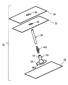
[047] FIG. 1 is a schematic expanded perspective view of a drape, flange,
connector
and tube kit components with first and second liners, prior to application of
a liquid sealant
according to the present invention;
[048] FIG. 2 shows the kit components of FIG. 1 with an adhesive patch
component according to the present invention positioned beneath the flange,
prior to
application of a liquid sealant according to the present invention;
[049] FIGS. 3A and 3B schematically illustrate a novel symmetrical flange
and
tube connector of FIGS. 1 and 2 being connected to form a symmetrical
connector assembly,
as illustrated in FIGS. 4A and 4B, with FIGS. 3B and 4B being side cross-
sectional views of
FIG. 3A and FIG. 4A, respectively;
[050] FIGS. 5 and 6 are a schematic perspective views of the tube of FIGS.
1 and 2
being connected to the novel, preferably symmetrical connector assembly of
FIGS. 4A and
4B;
[051] FIGS. 7A and 7B illustrate repositioning of the upright tube of FIG.
6 into a
desired side orientation;
[052] FIG. 8 is a bottom view of the novel flange of FIG. 3A-4B;
[053] FIGS. 9 and 10 show a drape being connected to an upper liner to
manufacture a dressing according to the present invention;
[054] FIG.11 shows a hole punched in the dressing of FIG. 10;
[055] FIGS. 12 and 13 shows a tube assembly being inserted onto the
dressing of
FIG. 11 with the edge of the flange being sealed to the drape;
[056] FIG. 14A shows the adhesive patch of FIG. 2 sealed to the flange and
drape
of FIG. 13;
[057] FIG. 14B shows an alternative adhesive patch sealed to the drape of
FIG. 13
and an alternative novel, preferably symmetrical flange;
[058] FIG. 15 shows a protective liner being adhered to the dressing of
FIG. 14B;
[059] FIG. 16 shows the protective liner being removed from the dressing in
FIG.
15;
- 17-
CA 02969472 2017-05-31
WO 2016/094742
PCT/US2015/065132
[060] FIG. 17 shows an alternative protective liner adhered to the dressing
of FIG.
14B;
[061] FIGS. 18A and 18B show the protective liner being removed from the
dressing in FIG. 17;
[062] FIG. 19 shows an alternative protective liner adhered to the dressing
of FIG.
14B;
[063] FIG. 20 is a schematic top plan view of a liner having perforations;
[064] FIG. 21A is a schematic top plan view of a liner having serrated
edges.
[065] FIG. 21B is a perspective view of the liner of FIG. 21A, after a hole
is
punched, adhered to the top of a dressing;
[066] FIG. 22 shows an exploded view on the left and, on the right, a
perspective
view after assembly of the liner of FIG. 20, after a hole is punched, adhered
to the top of a
dressing and as the liner is being removed;
[067] FIG. 23 shows an alternative exploded view on the left and, on the
right,
assembly of the liner of FIG. 20 adhered to the top of a dressing and the
liner being
removed;
[068] FIGS. 24-26 show the application of sealant to the edge of the
dressing by
sponge-type applicators of different shapes;
[069] FIG. 27 shows a powder applicator;
[070] FIG. 28 shows the activation of the powder applicator of FIG. 27;
[071] FIGS. 29-31 are schematic exploded views of powder applicators,
showing
their activations;
[072] FIGS. 32A and 32B show an exploded view of a novel cap, with FIG. 32B
being a partial cross-sectional view of FIG. 32A;
[073] FIG. 33 shows the cap of FIGS. 32A and 32B attached to a bellows
pump;
[074] FIG. 34 is a graph showing vacuum pressure versus compression length
of a
bellows pump;
[075] FIG. 35A shows external compression length limiters attached to the
pump of
FIG. 33;
[076] FIG. 35B shows the external compression length limiters being removed
from the pump;
- 18-
CA 02969472 2017-05-31
WO 2016/094742
PCT/US2015/065132
[077] FIG. 36 shows a novel internal compression length limiter added to a
cap
similar to the cap of FIGS. 32A-32B;
[078] FIG. 37A and 37B show an internal compression length limiter on a
pump,
with FIG. 37B being an enlarged, partial-cross-sectional view of FIG. 37A;
[079] FIG. 38A and 38B show structural support features on the top and
bottom of
a pump;
[080] FIG. 39 illustrates a novel pump carrying strap and integrated
pressure gauge;
[081] FIG. 40 shows the carrying strap of FIG. 39 being applied to a pump;
[082] FIG. 41 shows an alternative carrying strap being applied to an
alternative
pump;
[083] FIG. 42A and 42B illustrate the nesting of two kit trays;
[084] FIG. 43 illustrates a novel, unbacked liquid layer tape according to
another
aspect of the present invention;
[085] FIG. 44 is a graph showing the force versus strain relationship of
tension tests
on commercial wound dressings and a novel, unbacked liquid layer laminate
according to
the present invention;
[086] FIG. 45 illustrates a construction for a novel, unbacked liquid layer
drape and
adhesive patch for the kit of FIG. 2; and
[087] FIG. 46 is a schematic diagram of the manufacturing process for the
drape of
FIG. 45 according to the present invention.
DETAILED DESCRIPTION
[088] Described and claimed herein are novel tapes and methods including an
unbacked construction of at least one liquid layer adhesive that has been at
least one of dried
and cured. Also described and claimed are novel occlusive tissue dressings,
tapes and
methods including an elastomeric drape and, for backed drapes and some
unbacked drapes, a
liquid component, at least partially cross-linked at least after one of drying
and curing,
suitable for application at a dressing-to-skin interface in order to create a
substantially air-
tight seal. The same or a different liquid component may be applied by a user
at a tube-to-
dressing interface of an elastomeric drape to create a similar air-tight seal
around the tube, if
not occlusively sealed during its manufacture.
- 19-
CA 02969472 2017-05-31
WO 2016/094742
PCT/US2015/065132
[089] The occlusive wound dressing aspect of this invention may be
accomplished
by a kit, dressing system or method utilizing a drape formed as a thin sheet
of an organic,
preferably elastomeric material, substantially impervious to fluid transfer of
air and bodily
fluids for preferably at least 48 hours, more preferably at least 72 hours,
having first and
second surfaces. Preferably, a biocompatible adhesive is disposed on, applied
to or
contacted with, at least the first surface of the drape or is the base
material of the unbacked,
liquid drape. In a number of constructions, a first removable liner sheet
covers the first
surface of the drape and, optionally, a second removable liner sheet covers
the second
surface of the drape. Preferably, the drape is constructed of at least one
layer of an adhesive.
In certain constructions, the invention further utilizes a container of at
least one sealant
component that is capable of being delivered as a sealant in a liquid state at
pre-selected
ambient conditions, the sealant as delivered being at least partially cross-
linked at least after
one of drying and curing, and which is capable of at least one of drying and
curing within
thirty minutes, preferably within twenty minutes and, more preferably, within
ten minutes
after application of the sealant as a layer to the edges of the drape after
the drape is applied
to the skin surrounding the wound.
[090] The occlusive dressings presently disclosed address the
power/mobility and
air leak issues of NPWT by eliminating the need for an electrical power source
and by
maintaining reliably air-tight interfaces, particularly at 1) the dressing and
the skin and 2)
the tube and the dressing. The disclosed dressing systems and their connection
methods
allow for reliable, mechanical NPWT systems. Not only does this eliminate
patient mobility
and battery management issues, but it also allows NPWT to be administered in
austere
environments, where electricity is often scarce and harsh environments require
robust
products. Multiple disclosed embodiments support an inexpensive, robust
therapy method
for global application. Additionally, dressings according to the present
invention are MRI-
compatible.
[091] In its preferred construction, the wound drape component according to
the
present invention has a novel, unbacked liquid adhesive embodiment. It can be
manufactured using the same converting processes as utilized to manufacture
general
adhesive tapes and, therefore, this application discloses the embodiment in
the more general
sense of a novel, unbacked liquid adhesive tape. One skilled in the art would
realize, after
- 20 -
CA 02969472 2017-05-31
WO 2016/094742
PCT/US2015/065132
reviewing the present application, that this applies to embodiments for many
applications,
including wound drapes, skin tapes, structural tapes, and fabric tapes.
[092] Adhesive tapes, including certain wound drapes, are typically
manufactured
conventionally by coating a substantially non-tacky, structural backing with
adhesive. The
backing can be made of various materials, including paper, woven or non-woven
fabric, foil,
and polymer film or sheet. These backing materials often limit the
extensibility and elasticity
of the tape, as detailed in U.S. Patent No. 4,024,312 by Korpman. During the
conventional
tape manufacturing process, the backing is typically sourced in a roll that is
then unrolled
and coated with an adhesive on at least one of its sides. The backing
manufacture/rolling and
unrolling/coating processes often occur in two different facilities. In some
embodiments, the
adhesive may be further protected with a removable liner (a.k.a., release
liner). The
removable liner is typically applied after the adjacent adhesive did at least
one of at least
partially (1) drying and (2) curing on the backing. The final, layered
material (i.e., backing,
adhesive, and removable liner, if used) is typically rolled for further
processing.
[093] If no removable liner is used and only one surface of the backing is
coated
with adhesive, a conventional release coating is often applied to the backing
on the opposite
side of the adhesive, in order for the tape to easily be unrolled during
further processing
and/or its functional use. If adhesive is applied to both sides of the
backing, a removable
liner is typically applied to at least one of the adhesives; if only one
release liner is used, this
liner typically has a release coating on both sides for its release of both
adhesives: one upon
unrolling the tape and one as the liner is removed. In this conventional case,
the bond of the
release liner to the two adhesives must have a bond strength differential
large enough
between the two adhesives in order to properly be unrolled and then removed
during its use.
It must have a lower bond strength to the first adhesive that is removed from
the liner during
the unrolling process. The liner is typically removed from the second adhesive
after the first
adhesive is applied to a substrate. Therefore, in this conventional case, the
liner must have a
lower bond strength to the second adhesive than the bond strength between the
first adhesive
and the substrate that its attached to. During its functional use, the
adhesive (on one or two
sides of the backing) and the backing form the functional tape embodiment.
[094] The preferred functional tape embodiments according to the present
invention
are not made with a traditional, substantially non-tacky backing, as described
above for
conventional manufacturing processes. In one preferred embodiment, at least a
portion of a
- 21 -
CA 02969472 2017-05-31
WO 2016/094742
PCT/US2015/065132
transfer film is coated with a liquid polymer layer and at least one of at
least partially (1)
dried and (2) cured. The phrase "at least a portion" is coated includes
patterns of liquid
polymer layer, such as concentric circles or a grid of "dots" or lines. Then,
a second liquid
polymer layer may be directly coated over (i.e., in liquid form and allowed to
at least one of
at least partially (1) dry and (2) cure) or laminated to (i.e., laminated
after the second liquid
polymer at least one of at least partially (1) dries and (2) cures on a
transfer film) at least a
portion of the first layer. Sequential layers may be added thereafter, for
which a transfer film
may need to be removed, in order to expose at least a portion of a polymer
surface for
coating or laminating. To aid in the drying and/or curing process, the layered
constructions
may be placed in different environments. For example, one or more of the
following
techniques can be utilized: heat may be applied to the liquid layer;
particularly for hot melts,
the layer may be cooled; radiation may be applied; or the process may require
a combination
of processes in parallel or sequentially.
[095] In some techniques according to the present invention, the lamination
process
may include the lamination of a transfer film, with no additional polymer. For
the final
construction, the transfer film on at least one of the top and bottom of the
final layered
construction is not removed and takes the functional form of the removable
liner previously
discussed, and/or the transfer film on at least one of the top and bottom of
the final layered
construction is removed and replaced by a removable liner. One skilled in the
art would
realize that the individual layering of materials does not have to happen
sequentially, and
that subassemblies of layered constructions can in-turn be laminated to each
other. This
technique may be desirable to separate the processing temperatures and times
of the
subassemblies. One skilled in the art may consider certain final constructions
to be a
combination of layered adhesives. With this definition, each final
construction must have
enough cohesion in at least one layer to provide a functional construction
that maintains
cohesion throughout its functional use.
[096] One preferable method of construction is to coat each liquid polymer
layer
onto a transfer film and then sequentially laminate the polymer layers into
the final assembly
or separate subassemblies. After the individual layers are initially coated
onto a transfer film,
they are typically rolled (i.e., for transport or storage) after the polymer
layer does one of at
least (1) drying and (2) curing; therefore, in the preferred embodiment, the
transfer film has
a release surface on both sides, such that the layer can be unrolled and the
transfer film
- 22 -
CA 02969472 2017-05-31
WO 2016/094742
PCT/US2015/065132
removed. Otherwise, a second transfer film would need to be applied to the
polymer layer
before rolling it.
[097] Initially, for each assembly or subassembly, a base liquid polymer
layer may
be first laminated onto another transfer film and its original transfer film
removed, or in the
preferred process, it is used with its initial transfer film. Each layer
(i.e., individual layer or
subassembly of multiple layers) is laminated sequentially to another layer,
and then, one of
the transfer films of the resulting embodiment is removed prior to its next
lamination step, in
order to expose the polymer to be laminated. During the process, a lamination
step may be
used to laminate a layered construction to a new transfer film, during which
no new liquid
polymer layers are added. This may be done in order to create the necessary
bond strength
between the transfer film and its adjacent adhesive; for instance, a film with
a weak bond
strength may be replaced with a film with a stronger bond, in order to peel
the film from the
opposite side of the laminate. In addition, in the case that a subassembly or
final assembly is
rolled (i.e., for transport or storage) and one of its transfer films is
removed, the remaining
transfer film must have a release surface on both sides, such that the
subassembly or final
assembly can be unrolled and the transfer film removed in the future.
[098] If at least one of the top and bottom polymers is attached to a
removable liner
in the final functional construction, one or more final removable liner(s) can
be laminated
onto the fmal construction during the conversion process, or the original
transfer film(s) of
the final laminate can be used as the removable liner(s). An example of a case
where a new
liner would be introduced is if the desired removable liner could not be used
in the
individual layer coating process onto a transfer film, due to heat
sensitivities or bond
strength issues. This may also be the case when the original base transfer
film is needed for
its stronger bond strength to the base layer during the stripping of
subsequent transfer films
during the lamination process, however, after the layering is complete, a
different base
removable liner is preferred in the final embodiment. In this case, the top
transfer film would
need to have a strong enough bond to the laminate for the base (i.e., bottom)
transfer film to
be removed and replaced with the new removable liner. If only one removable
liner is used
and if the laminate is rolled onto itself, the removable liner must have a
release surface on
both sides, such that the laminate can be unrolled and the liner removed, as
previously
discussed. In one preferred embodiment, a removable liner is on an least the
side of the
laminate opposite the side first attached to a substrate during functional
use. This allows the
- 23 -
CA 02969472 2017-05-31
WO 2016/094742
PCT/US2015/065132
tape to be easily handled during its functional application. If two removable
liners are used,
the base and top liners in .the final embodiment should have the proper
bonding strength
differential for functional use of the dressing. For instance, if the base
liner is to be removed
first, it should have less bonding strength during its removal. Transfer film
and removable
liner bond strengths can be varied by peel angle and set time, during
lamination and
functional use.
[099]
During manufacture and use of this layered embodiment, the bond strengths
between all of the adjacent polymer layers are ideally larger than the bond
strength (a.k.a.,
adhesion or adhesive strength) of any transfer film or removable liner to its
adjacent polymer
during its removal. If two transfer films or removable liners are used to
sandwich at least
one polymer coating during manufacture or use, respectively, the film or liner
that is to be
removed first should have less bond strength to its adjacent layer during its
removal than the
film or liner to be removed second. This allows for the films or liners to be
easily removed
without delaminating any other interface. In some embodiments, a transfer film
or
removable liner is removed by pulling the film or liner with at least one of a
specified (1)
angle and (2) speed, or within a range of specified (1) angles and (2) speeds,
in order to
reduce the effective bond strength of the film or liner to the adjacent layer
and create the
necessary bond differential for removal (this variable adhesive strength
(i.e., peel force) vs.
peel angle is described when peeling tape off of a substrate in U.S. Patent
No. 5,516,581 by
Kreckel et al.; peeling the film or liner off of the polymer layer or laminate
adheres to the
same mechanics principles). Although it is not preferable, selected
environmental
conditions such as temperature can also be varied to vary the peel force
differential between
layers. Additionally, the bond strength of an adjacent liquid polymer to the
film or liner
typically increases over time before reaching its maximum value. Therefore,
temporary
liners during the lamination process may be used in a time dependent manner.
[0100]
The layers each need the proper adhesion-cohesion balance, in order to
provide the proper adhesive strength to the adjacent layers or desirable
substrates and the
proper cohesive strength for the desired mechanical performance properties. In
the preferred
embodiment, the liquid layers are adhesives (i.e., after at least one of at
least partially (1)
drying and (2) curing, all viscoelastic liquids, all viscoelastic solids, or a
mixture of
viscoelastic liquid and solid layers), and therefore, since they are
viscoelastic, they possess
the characteristics of both liquids and solids. In the preferred embodiment,
they are all
- 24 -
CA 02969472 2017-05-31
WO 2016/094742
PCT/US2015/065132
coated in liquid form onto transfer film prior to any lamination processes. In
one preferred
embodiment, all of the layers are pressure sensitive adhesives (a.k.a., PSAs),
and are
manufactured using at least one of (1) solvent, (2) hot melt, (3) emulsion,
(4) radiation, (5)
suspension, and (6) other solution processes. The transfer film provides the
mechanical
structure necessary for the rolling and unrolling processes and for any
lamination processes.
With the proper balance of adhesion and cohesion, an unbacked construction of
liquid layers
according to the present invention may be transferred onto a substrate with a
removable
liner, and embody the functional properties of a typical tape laminate of at
least one adhesive
layer and backing layer. However, based on the present invention, mechanical
properties of
the present tape embodiment can be achieved, which are not possible by
laminating a typical
backing layer. Materials that are difficult to handle or infeasible to make in
the standard
backed embodiment may be fabricated. One skilled in the art would realize that
the liquid
layer construction may also be used as a component in other assemblies, such
as border
dressings.
101011 One benefit of this tape embodiment with a liquid construction
method
according to the present invention is that it can use more desirable materials
for enhanced
functional performance, compared with the standard backings readily available
today.
Additives to the materials can be easily mixed into the liquid formulation
prior to its layer
application, in order to alter the properties of the final embodiment and
fabricate tapes from
custom materials. Elastomeric materials are ideal, although plastic and
elastomeric materials
may be used. At least one layer of rubber, such as a polyisoprene rubber (IR)
based or
natural rubber latex based formulation, may be preferred, due to its desirable
elastomeric
properties for this invention. In some embodiments, the liquid layers may
suspend addition
components, such as: pharmaceuticals, antimicrobials, hydrocolloids, UV
protectant,
alginates, and dyes. Based on the liquid coating process for each layer, these
are easily
integrated into the design.
[0102] In one preferred embodiment of this invention, two layers are
sandwiched
between two removable liners. First, a liquid rubber adhesive (i.e., a
synthetic, natural, or
synthetic-natural hybrid rubber; preferably an emulsion) is coated onto a
transfer
film/removable liner that it adheres to upon at least one of at least
partially (1) drying and
(2) curing. The final rubber embodiment is cross-linked such that it has a low
rubber
modulus, allowing for easy stretch-ability (i.e., high extensibility), and a
high elastic
- 25 -
CA 02969472 2017-05-31
WO 2016/094742
PCT/US2015/065132
recovery. Preferably, the elastic recovery from 50 percent stretch is at least
75%, and more
preferably at least 90%, and even more preferably at least 95%. The material
properties are
discussed in further detail below.
[0103]
The final rubber embodiment is a solid viscoelastic material layer that is
tacky on both of its surfaces. One skilled in the art would commonly refer to
this layer as an
adhesive layer. This highly elastic layer would be very difficult, if not
impossible, to handle
as a traditional backing roll. Rubber emulsions are often tacky, and
therefore, they cannot
easily be rolled onto themselves without processing steps to remove the tack.
For example,
coating the material with a powder and/or liquid sealant can remove the tack,
which would
alter the ability to coat or laminate the rubber directly with adhesive, as
the powder and/or
sealant would need to be removed first. In addition, the easy stretch-ability
of this layer
makes it difficult to handle without a stiff backing layer of its own attached
for processing,
in this case the transfer film/removable liner allows for easy handling,
including the rolling
and unrolling processes.
[0104]
The rubber layer coated onto a transfer film/removable liner is coated or
laminated with a second functional pressure sensitive adhesive (PSA). In this
case, the initial
rubber layer is used mostly for its cohesive strength and the second PSA is
used for its
functional adhesive strength. In the preferred embodiment, the second PSA is
laminated to
the rubber, after the PSA is coated onto a transfer film/removable liner. In a
preferred
embodiment, the second PSA is a silicone-based adhesive. In another preferred
embodiment,
the second PSA is an acrylic-based adhesive, including a modified acrylic
adhesive. In
another preferred embodiment, the second PSA is a rubber-based adhesive.
Pressure
sensitive adhesives that may be used in this embodiment include tackified
rubber adhesives
(i.e., natural rubber, olefins, silicones, polyisoprene, polybutadiene,
polyurethanes, styrene-
isoprene-styrene and styrene-butadiene-styrene block copolymers) and other
elastomers; and
tackified or untackified acrylic adhesives (i.e., copolymers of
isooctylacrylate and acrylic
acid, which can be polymerized by radiation, solution, suspension, or emulsion
techniques,
including vinyl ethers and ethylene-vinyl acetates (EVA/PVAs)). Crosslinked
adhesives may
be preferred, especially those pressure-sensitive adhesives crosslinked to
give higher shear
strengths (a.k.a., cohesive strengths). Adhesives with a high peel adhesion to
the end
substrate may be preferred, due to high bond strength.
- 26 -
CA 02969472 2017-05-31
WO 2016/094742
PCT/US2015/065132
[0105] The
second PSA adhesive adheres to the rubber layer after at least one of a
(1) lamination process and partially (2) drying and (3) curing. A protective,
removable liner
is preferably applied to both sides of the adhesive layers by leaving the
transfer film on each
side from the original adhesive coatings or by laminating a new removable
liner onto the
surface. If the construction is made by coating multiple adhesives on top of
one another,
without lamination, then a second removable liner needs to be laminated on top
of the
layered embodiment. In this case, it should be noted that the manufacturing of
the layers
may be in the opposite sequence: coating a second removable liner with the
second PSA
functional adhesive and coating the second PSA with the rubber adhesive and
then
laminating the layered embodiment with a first removable liner.
[0106] In
certain tape embodiments under the scope of this invention, a specific
manufacturing sequence may be necessary, depending on any required heating or
cooling
processes and/or the necessary adhesion strength and cohesion strength of each
layer and/or
UV curing process. For instance, a high temperature may create too strong of a
bond
between the desired removable liner and its adjacent layer, yet the layer may
require that
temperature for at least one of (1) drying and (2) curing. Therefore, the
layer must be first
coated onto a transfer film prior to its removal and the lamination of the
desired removable
liner, or it must be coated directly onto its adjacent adhesive prior to the
application of the
desired removable liner. In another instance, the bond strength required
between two
adhesive layers may require a coating process of one adhesive directly onto
the second
adhesive, or may require a primer coating to be applied to one adhesive for a
stronger bond
strength when laminating the two layers. In another instance, the application
of heat may
continue to strengthen the bond between a desirable transfer film/removable
liner and its
adjacent layer, which might not be ideal. Therefore, if heat is necessary to
at least one of (1)
dry and (2) cure subsequent layers, those layers must be at least one of (1)
dried and (2)
cured before being layered to both the adjacent layer of the desirable
transfer film/removable
liner and the desirable transfer film/removable liner. In one preferred
manufacturing process,
each layer is sequentially laminated to the construction. Therefore, the
adhesion and
cohesion of each layer of the current construction must be able to withstand
the removal of
the transfer film currently being removed, until the final embodiment is
achieved. Although
heating and/or cooling may be applied during lamination, it is not preferred.
Also, the
-27-
CA 02969472 2017-05-31
WO 2016/094742
PCT/US2015/065132
coating of primers directly onto the coated adhesive layers for increased
adhesion is not
preferred.
[0107]
The previously described, preferred embodiment (i.e., rubber layer and
second PSA laminate) may be used to make highly extensible tape that can
adhere to highly
extensible substrates without delamination (due to the high elasticity of the
rubber layer, the
high adhesion of the second PSA to the substrate, and the strong bond between
the adhesive
layers). The adhesion of the PSA to a substrate (a.k.a., adherend) depends on
many
variables, including the ability of the adhesive to wet (i.e., flow onto) the
substrate, the
ability of the adhesive to resist flow when stress is applied, and the
strength of the molecular
forces involved in the resulting bond. The PSA tape typically bonds to a
substrate with Van
der Waals forces, which contribute significantly to the ultimate bond strength
and also
depend on the proper wetting of the surface. The ability of Van der Waals
forces to provide
adequate bond strength is based on the material and thickness of each layer of
the tape.
Typically, the thickness of each layer of material is constant.
[0108]
Theoretically, for tape (in general) to remain adhered to the substrate, the
debond toughness (strength of the bond) must be greater than the debonding
energy, and the
debonding energy is proportional to: the thickness of the material, the strain
in the material
squared, and the elastic modulus of the material. Specifically (on a first
order basis; as its
basis is a small strain analysis), the bond strength of a thin film must abide
by Equation 1,
where F is the debond toughness, is the debonding energy, CI is a
dimensionless prefactor,
which depends on the crack pattern, h is the thickness of the film, ET is the
strain in tension,
and Ef is the elastic modulus of the film, in order to maintain adhesion to
the skin in tension:
F > = C2hET2Ef (1)
Equation 1 shows the debonding energy for a homogeneous, isotropic, a linear
elastic, thin
film layer, and an infinitely thick substrate. More specifically, Equation 1
is based on small
strains, and therefore, should only be used on a first order basis for the
function of highly
extensible tapes. For the application of a multi-layered tape, the debonding
energy, g, is
dictated by Equation 2. This equation also assumes homogeneous, isotropic,
linear elastic,
thin film layers, an infinitely thick substrate, and small strains; therefore,
it should be used
on a first order basis for highly elastic tapes on thick substrates. The
energy released per unit
area of the tape is:
- 28 -
CA 02969472 2017-05-31
WO 2016/094742
PCT/US2015/065132
F
(2)
= hinEfn
1
where 0 is a dimensionless prefactor, which depends on the crack pattern,
izfr; is the
thickness of the nth film layer, Efn is the elastic modulus of the nth film
layer and Er is the
strain in tension. Therefore, tape with the same bond strength (i.e., same
contact adhesive
and substrate properties, including the bond between them) will remain bonded
during
increased strain deformations, as the thickness of its layers decrease and/or
the modulus of
its layers decrease. This broadens the use of a highly elastomeric tape
embodiment with thin,
highly elastic layers, and it highly favors the liquid construction layers in
this invention and
their corresponding mechanical properties over the properties achievable with
standard
coated backing materials. Note that we assumed a perfect, permanent bond
between the
construction layers for this first order analysis.
[0109] The
construction layers in the current invention can reach minimum
thicknesses and minimum moduli when compared to tape embodiments that
currently exist.
This is due to the elimination of the solid backing. Instead of a solid
backing, a liquid layer
with enough cohesive strength for functional use is used. Through
experimentation, natural
or synthetic rubber adhesives were suitable for this function in the layered
construction.
With a completely liquid tape, the superior extensibility of rubber or another
highly
extensible, elastic liquid-applied polymer is typically the limiting modulus
(i.e., increasing
the debond energy the most with strain), as the rubber layer typically has the
highest
modulus. In addition, the liquid layers can often be applied much thinner in a
coating
process than a typical, solid backing can be made.
10110] In
addition to usability, another additional benefit of such a low modulus,
highly extensible tape is its removability from the substrate. In the
preferred embodiment
previously described (i.e., rubber and PSA laminate), the linear elastic
modulus (in the linear
elastic region) can be much lower than is currently available in tapes, the
knee of the stress
versus strain curve can be much lower, and in some cases, the moduli through
large
defmmation after the knee can be lower. As the user pulls on the tape for
removal, the tape
has a large deformation with a low force. In a general theoretical analysis,
stretching the tape
is storing energy in the tape that is used to break its adhesive bond to the
substrate. The
substrate will also deform to store energy that is used to break the adhesive
bond. The stored .
- 29 -
CA 02969472 2017-05-31
WO 2016/094742
PCT/US2015/065132
energy of the tape and the substrate is equivalent to the area under their
corresponding stress
versus strain curves that define the mechanics of the deformation.
[0111] In
order not to tear, deform, delaminate (in the case of paint on a wall or skin,
for instance), or otherwise undesirably alter the substrate material, a tape
that has a lower,
preferably much lower, modulus throughout its deformation than the substrate
is desirable;
the knee in the stress versus strain curve for the tape is preferable to occur
at a low stress
compared to the substrate knee and/or yield point, and the tape must have the
necessary
elongation before break to be removed from the substrate. During
experimentation of the
preferred embodiments, the user may re-grip the tape closer to the substrate,
in order to
maintain their grip within a feasible and controllable distance from the
delamination fracture
line. In addition, a thinner tape and thicker substrate is desirable, in order
to increase and
decrease, respectively, the applied stress corresponding to an applied force;
ideally, the
maximum force applicable to the tape during its use is not damaging to the
substrate.
Therefore, it is desirable for the tape to store most of the energy,
especially when more
delicate and fragile substrates are adhered to. In addition, keeping the
substrate constant, an
adhesive with a higher adhesive strength to the substrate can be used with the
same impact
on the substrate upon removal, if the tape stores the additional energy needed
to break the
higher adhesive bond. Therefore, lower linear modulus, lower knee stress,
large elongation
with lower rubber moduli, and thinner thickness of a tape all contribute to
the ability to use a
contact adhesive with a stronger adhesive force to the substrate with the same
impact on the
substrate upon removal. The current patent application describes a technology
that may
allow aggressive adhesives (i.e., high bond strength) to be used in tapes for
certain
substrates, which are not currently capable of being used in tapes for those
substrates.
[0112] As
described in U.S. Patent Nos. 4,024,312 and 5,516,581, the removability
may vary with the angle of removal, based on adhesive strength variability
with the peel
angle. Therefore, a tape embodiment with at least one of lower linear modulus,
lower knee
stress, large elongation with lower rubber moduli, and thinner thickness also
contributes to
the ability for a user to be able to vary the angle of removal of a tape with
a specific
adhesive, without damaging the substrate. This may increase the usability and
human
factors of the tape and may decrease instances of improper use. The contact
adhesive is
preferably highly extensible, does not separate from the lamination during
stretching, and
has higher cohesion than adhesion to any suitable substrate.
- 30 -
CA 02969472 2017-05-31
WO 2016/094742
PCT/US2015/065132
[0113]
After being applied to a substrate, the adhesive tape of the present invention
becomes firmly bonded, but can be easily removed without damaging the
substrate by
simply stretching it. In general, stretchable tapes provide a low debonding
force from the
surface of a substrate at low angles by simply stretching the tape. Since the
tape described in
this embodiment is highly stretchable, the force of removal may be in any
direction.
However, in order to minimize the force, it may be preferable to apply the
force less then 900
to the surface of the substrate and more preferably parallel, i.e., less than
about 450, to the
surface of the substrate. Tensile strength at break should be sufficiently
high so that it will
not rupture prior to the removal, and therefore, the tape can be removed in
one piece. A low
Young's modulus is preferable. If the modulus is too high, it is very
difficult to stretch the
tape sufficiently to cause clean release upon stretching. In the preferred
embodiment, the
tape typically forms into a polymer ball after it is removed, similar to a
ball of rolled rubber
cement. This ball is due to the adhesive and elastic properties of the layered
tape
embodiment.
[0114]
One preferred application of the preferred tape embodiment described of a
low modulus, highly extensible rubber and PSA laminate is in tissue tapes,
particularly for
the surface of the skin. A lower linear modulus, lower knee stress, large
elongation with
lower rubber moduli, and thinner tape thickness increases its wearability, as
the tape easily
stretches with the skin, while maintaining its adhesive bond. For many uses of
skin tape, this
may allow free mobility of the user with a reduced sense of the applied tape,
increasing user
comfort. With the rubber and PSA laminate, the linear modulus, rubber moduli
at specific
strains, and knee stress can be reduced by an order of magnitude compared to
current tape
embodiments; this is a key factor in its increased wearability and comfort.
[0115] An
additional benefit of a lower linear modulus, lower knee stress, large
elongation with lower rubber moduli, and thinner tape thickness is that the
wear time of a
particular contact adhesive may increase. For instance, secreted body fluids
over time may
decrease the debond toughness, which can cause the tape to delaminate from the
surface of
the skin as the person moves, on a first order basis according to Equations 1
and 2 above.
However, with a decreased modulus and/or thickness, the debonding energy of
the tape
deformation is significantly reduced, allowing for good adhesion through a
higher
magnitude of decreased debond toughness.
-31 -
CA 02969472 2017-05-31
WO 2016/094742
PCT/US2015/065132
[0116] In
addition to wearability and comfort, tissue tapes preferably do not cause
pain for the user upon removal. Pain typically originates from the deformation
and/or
damage of the tissue (i.e., substrate), as the tape is removed. Therefore, as
previously
discussed, the rubber and PSA embodiment can reduce the deformation of the
tissue upon
tape removal, which may reduce the feeling of pain and/or damage to the
tissue, such as skin
tears.
[0117]
Using the disclosed tape technology, this technology disclosure is further in
the field of wound dressings with an adhesive film embodiment, which is used
to cover a
wound (i.e., wound drape component). Below is the description of a preferred
wound
dressing with the preferred tape embodiment previously discussed (i.e., rubber
and PSA
laminate). Although natural rubber adhesive may be used, synthetic rubber
adhesive is a
preferred material in many cases. Synthetic rubber material typically does not
have a carbon-
to-carbon backbone that can leave it susceptible to ozone, UV, heat and other
ageing factors.
Synthetic rubber materials also generally come with good levels of chemical
and
temperature resistance, depending on their formulation. They also typically do
not have
proteins, which cause contact allergies.
[0118] The
dressing linear modulus, knee of the stress versus strain curve, and
thickness play important roles in the application of the wound dressing. When
applying the
dressing, the user must apply a planar, flexible dressing onto the skin
surface that is typically
not planar. Therefore, the user must maneuver the dressing to match the
contour of the skin
upon its adhesive application. During this process, the user may bridge skin
contours, skin
wrinkles, and/or folds in the skin. Once applied, the only ways to create skin
adhesive
contact on areas of the skin that were bridged is (A) for larger bridges: (1)
to remove the
dressing and reapply it, trying to avoid any bridging during the second
dressing application,
or (2) to apply pressure on the drape over the bridge to stretch the drape and
adhere it to the
skin underneath, and (B) for smaller bridges: (3) to wet the surface with the
skin contact
adhesive.
[0119] For
the first solution, it is often not ideal to remove and reapply the dressing,
as the skin adhesive will remove dead skin cells and other debris from the
skin's surface and
adhere to particles in the atmosphere. With these particles bonded to the skin
contact
adhesive, the skin contact adhesive bond is less strong during dressing
reapplication to the
skin's surface.
- 32 -
CA 02969472 2017-05-31
WO 2016/094742
PCT/US2015/065132
[0120]
For the second solution, a lower effective modulus (and depending on
elongation, a lower stress for the knee of the stress versus strain curve) of
the dressing is
ideal, as a tensional strain is applied to the dressing during the application
of pressure and a
higher modulus further increases the debonding energy of the dressing,
according to
Equation 2 on a first order basis. Hence, with this solution, there is a
residual force against
the bonding force of the skin contact adhesive to the skin. Increased
thickness also increases
the debonding energy of the dressing when a tensional strain is applied,
according to
Equation 2 on a first order basis. However, the thickness of thin film
dressings are often on
the same order of magnitude, and therefore, the linear modulus and potentially
the knee of
the stress versus strain curve subsequently play a larger role in delamination
of the dressing
from the skin in many embodiments.
[0121]
For the third solution, the wetting of the skin contact adhesive often
corresponds with the adhesive bond strength. Therefore, the wetting properties
of the
adhesive are typically limited by the ability to remove the dressing without
causing pain or
tissue damage to the patient. In practice, the bridges are often not
completely removed from
the dressing, due to the remedies available and the desired end function. For
the reasons
stated above, the dressing technology presented in this patent application can
allow for
more, if not all, bridges to be further resolved during application and wear,
creating a sealed
wound environment.
[0122] As
previously discussed, the modulus, knee stress, rubber moduli through
large deformations, and thickness also directly affect dressing function and
wearability. As
the modulus of the dressing and effective thickness increase, the skin
adhesive bond strength
to the skin must also increase, in order to stay on the skin and prevent
delamination during
body movements (i.e., applied strains). In addition to adhesive function, the
patient comfort
and dressing wearability increases with decreasing modulus and thickness. This
is because
the surface of the skin underneath the dressing moves with less resistance
from the dressing
with a lower dressing modulus and thickness; this puts less trauma on the skin
surface over
time, as the shear force of the skin adhesive to the surface of the skin is
also reduced.
Minimal dressing thickness also decreases the bending stiffness of the
dressing, further
increasing comfort and wearability. These characteristics favor the current
invention
embodiments over current commercial wound dressings.
- 33 -
CA 02969472 2017-05-31
WO 2016/094742
PCT/US2015/065132
[0123]
When the dressing is removed, it is ideal for the fracture surface to be the
surface between the skin adhesive and the surface of the skin. This is based
on the balance of
cohesion and adhesion of the materials in the tape and the substrate, which
strongly relate to
their mechanical properties (i.e., modulus throughout its deformation; the
knee and/or yield
point in the stress versus strain curve, and the elongation before break), as
previously
discussed. For some wound dressings, the fracture surface may be in the layer
of the skin
adhesive or between the surface of the skin adhesive and the backing material;
in these
cases, an adhesive residue is left on the skin, which is typically removed
prior to another
dressing application. In the preferred embodiment, the cohesion of the
dressing layers and
the adhesion between layers allow for the dressing to be removed with no
residue left
behind. A dressing that causes tissue failure (i.e., fracture in the
substrate) upon removal is
not desirable.
[0124]
Prior to the formation of the fracture surface, a force must typically be
applied in removing the dressing. The force is typically applied when the
dressing is peeled
off manually by the caregiver. As previously discussed, the modulus, knee
stress, rubber
moduli through large deformation, and thickness play a key role in the removal
of the
dressing. Pain typically originates from the deformation of the tissue, as the
dressing is
removed. Therefore, as previously discussed, an embodiment with a lower
elastic modulus,
lower knee stress, large elongation with lower rubber moduli, and thinner tape
thickness can
reduce the deformation of the tissue upon tape removal, which may reduce the
feeling of
pain and damage to the tissue, such as skin tears. The rubber and PSA laminate
disclosed in
this application describes such an embodiment that reduces pain upon removal,
which has
been proven for wound dressings in both the lab and clinical settings (see
U.S. Provisional
Patent Application No. 62/090,350 filed 10 December 2014 by the present
inventor). As the
linear modulus, knee stress, thickness, and/or potentially the rubber moduli
during large
deformation decrease, the skin adhesive bond of a particular adhesive
effectively increases
during functional wear, according to Equations 1 and 2. Additionally, as the
linear modulus,
knee stress, thickness, and/or potentially the rubber moduli during large
deformation
decrease, the skin adhesive with an increased bond strength to the skin can be
used, while
maintaining the same or increasing patient comfort level and maintaining the
same or
decreasing tissue effects upon removal.
- 34 -
CA 02969472 2017-05-31
WO 2016/094742
PCT/US2015/065132
[0125] An
application of the current tape invention may be applied to wound
dressings that are highly flexible, in order to aid in dressing application
wettability, increase
wearability and comfort, and reduce tissue deformation and trauma upon
removal.
Preferably, the dressing is made of at least four layers. The first layer is a
removable liner
(i.e., carrier liner), onto which a second layer of an elastomeric organic
polymer adhesive
(preferably a rubber emulsion) is coated or laminated. Organic in this case
means that the
material contains carbon. After at least one of (1) drying and (2) curing, the
rubber layer is
coated or laminated with a skin contact adhesive layer, preferably a silicone,
acrylic, or
rubber-based polymer, which is protected with a final removable liner that is
directly coated
with the skin contact adhesive or that is laminated to the skin contact
adhesive.
[0126] The
wound dressing embodiment of rubber and PSA laminate described in
the present application is tacky on the surface away from the skin, after the
dressing is
applied to the skin and its carrier liner is removed. As referenced in the
parent application,
now U.S. Patent No. 9,173,777, this property can assist in pressing down the
folds on top of
the wound dressing, which form due to the geometrical mismatch of the wound
dressing and
the skin surface. As described in U.S. Provisional Patent Application No.
62/090,437 filed
11 December 2014 by the present inventor, the dressing technology described in
this
embodiment was effective as a reliable, occlusive wound dressing (handmade in
small
batches) when combined with a liquid sealant in the clinic; the sealant
technique is further
described in U.S. Patent No. 9,173,777. The dressing described in U.S.
Provisional Patent
Application No. 62/090,350 filed 10 December 2014 coats multiple liquid layers
of rubber
emulsion directly onto each other after each previous layer at least one of
(1) dried and (2)
cured, prior to applying one or two layers of skin contact adhesive after each
previous layer
at least one of (1) dried and (2) cured. In most cases, the adhesive was
coated onto the
rubber layers bedside in U.S. Provisional Patent Application No. 62/090,350,
and in these
cases, a protective removable liner over the adhesive was not applied. After
the final
dressing was applied, the tacky outer surface of the dressing was covered in
powder, in order
to prevent the outside of the dressing from sticking to other surfaces and to
decrease the
coefficient of friction between the dressing and any other surface during its
wear time.
[0127]
Further material selection was pursued beyond the work presented in U.S.
Provisional Patent Application No. 62/090,350, in order to enhance the
mechanical and
chemical properties of the occlusive wound dressing and its manufacturability.
In result, the
- 35 -
CA 02969472 2017-05-31
WO 2016/094742
PCT/US2015/065132
rubber and PSA laminate was able to be applied reliably air-tight to the skin,
often without
an additional sealant (although sealant is used in the preferable embodiment,
for reliability
of occlusive properties for all skin types, body locations, and wear times).
This was due to
increased wettability during the dressing application and post application
(i.e., by pressing
the dressing into any bridges) processes, due to the high elasticity of the
layered
embodiment. In addition, the increased adhesive (i.e., wetting and adhesive
bond), liquid
(i.e., viscous), and elastic (i.e., lower modulus) properties of the laminate
allowed any air
paths to close completely upon user-applied compression force; as the required
force
decreases, the user reliability increases in closing off any air-paths. One
factor that increased
this reliability was using a thicker, more tacky skin contact adhesive,
preferably above 4
mils.
[0128] In
addition to a new skin contact adhesive with a stronger bond to the skin,
the rubber materials in U.S. Provisional Patent Application No. 62/090,350
were replaced, in
order to eliminate proteins; therefore, a synthetic rubber-based adhesive was
used. With this
material selection, extended wear times encountered an additional issue with
the rubber and
PSA laminate used, based on their cohesive properties. Pin holes began to form
during
extended dressing wear, particularly at locations where the substrate
significantly changed
mechanical properties, such as between the skin, gauze, and tube flange. These
pin holes
propagated through the dressing, causing air-leaks over time. This pin hole
issue in thin
films is often seen in the film packaging industry, the fuel cell industry,
and in large
balloons. In the NASA Tech Brief ("Multi-Layer Laminated Thin Films for
Inflatable
Structures"), it is suggested that for inflatable structures, a multi-layered
laminate will
reduce the occurrence of pinholes over a monolayer film. During our
experimentation, this
was also proven to hold true for tape laminates in the current invention.
[0129] One
preferred embodiment for an occlusive wound dressing was an eight
layer laminate with a 4 mil skin contact adhesive laminated to 2 mil of rubber
adhesive,
laminated to 1 mil of acrylic adhesive, laminated to 2 mil of rubber adhesive,
laminated to 1
mil of acrylic adhesive, laminated to 2 mil of rubber adhesive, laminated to 1
mil of acrylic
adhesive, laminated to 2 mil of rubber adhesive. This broke-up an 8 mil rubber
layer, which
provided enough cohesion to provide the structural integrity of the tape, into
4 layers. This
resulted in similar mechanical properties, but reduced the probability of any
pinhole
propagation through the multiple laminate layers. The new dressing embodiment
remained
- 36 -
CA 02969472 2017-05-31
WO 2016/094742
PCT/US2015/065132
occlusive during five day wear in our in vitro experimentation; the contact
adhesive on the
dressing adhered to skin, gauze packing, and the tube flange. In this new
embodiment, it is
preferable to have a higher number of layers for the same thickness of
material, as long as
the thickness of each layer of material achieves its mechanical integrity
during the coating
process. However, this must be balanced with the time to coat and laminate
each layer and
the corresponding expense. Also, the adhesion between layers must also remain
intact during
wear. The manufacturing of a multilayered liquid tape embodiment for a wound
dressing is
the same as that previously discuss for tape in-general. This multilayered
liquid laminate has
uses outside of wound dressings in the tape industry, where pinholes are not
preferable.
Pinholes may propagate into large tears over time, and therefore, they should
ideally be
avoided in any tape application. Increasing the number of layers of the layers
beyond the
contact adhesive is ideal to solve the pinhole issue. These new layers should
alternate in
materials, where an added liquid layer/material may be necessary, in order to
stop
propagation.
[0130] In order to obtain an air-tight skin dressing, the present
occlusive dressings
preferably use a liquid sealant; this liquid sealant must be utilized if the
liquid layered drape
embodiment, previously discussed, is not used. This liquid sealant may dry and
cure fast,
even immediately or effectively immediately, upon application to the skin or
other dressing
components, into a continuous, occlusive film or sheet of material. The drying
and curing
processes may occur simultaneously, may be driven by evaporation, may require
a curing
agent and/or accelerator, and/or may be enhanced or controlled with a curing
agent and/or
accelerator. Any extra additives (e.g., curing agents and accelerators) may be
added just
before, during, and/or after the sealant application process, depending on its
chemical
reaction with the sealant and its rate.
[0131] The liquid sealant bonds to the component(s) that it is meant to
seal. The
ability of Van der Waals forces to provide the bond strength without an added
adhesive or
other primer (for example, Skin-Prep by Smith and Nephew, London, U.K.) is
based on the
material and its thickness. Theoretically, the debond toughness (strength of
the bond) must
be greater than the debonding energy, and the debonding energy is proportional
to: the
thickness of the material, the strain in the material squared, and the elastic
modulus of the
material. Specifically (on a first order basis; as its basis is a small strain
analysis), the bond
strength of a thin film must abide by Equation 1 above. Therefore, a highly
elastic, thin film
- 37 -
CA 02969472 2017-05-31
WO 2016/094742
PCT/US2015/065132
presents the ideal material properties for reduced, required adhesion
strength, increasing the
functional applicability of the Van der Waals forces.
[0132] An additional adhesive, such as a silicone-based, rubber-based
(including
natural latex rubber), or acrylic-based glue, having one or more components,
might be
employed to produce the desired bond strength (for example, Liqui-Tape
Silicone Adhesive,
Waterproof by Walker Tape Co., West Jordan, UT). This adhesive can be applied
under the
liquid sealant or chemically mixed with the liquid sealant prior to its
application, depending
on its chemical make-up and final mixing properties. When applied under the
sealant, the
adhesive may need to become tacky (a.k.a., applied set time) prior to sealant
overlay. A fast-
setting, two-part sealant that is mixed prior to use may be useful in some
circumstances,
such as Skin Titee silicone available from Smooth On, Easton, Pennsylvania,
which is
ACMI Certified Safe and may be used by itself or mixed with a thickener, such
as Thi-vex
thickener, also available from Smooth On. A polymer sealant, or other material
with the
ability to bond into a continuous occlusive sheet, with adhesive-like
properties due to high
Van der Waals forces may be desirable, where no additional adhesive is needed.
[0133] Rubber polymers, such as latex, synthetic rubber, and
hypoallergenic latex,
are examples of polymers with desired properties for both the dressing-to-skin
and tube-to-
dressing interfaces. For example, Deviant Liquid Latex from Deviant, a
subsidiary of
Envision Design, San Jose, CA and Liquid Latex Fashions Body Paint from Liquid
Latex
Fashions, Warrington, PA were both demonstrated to seal the dressing at both
dressing
interfaces. The drying and curing time for the latex was significantly reduced
by applying
the liquid to the skin with an atomization process or with a saturated sponge
technique,
which are further disclosed in the sections below; by adding alcohol, which
helps to absorb
the water that evaporates from the latex; and/or by flowing a gas across the
sealant for
convection drying. For most applications, the curing/drying time was lowered
to
immediately (at most 1 minute) from the 5-10 minutes previously stated by
Deviant at
http://www.liquidlatex.net/.
[0134] Examples of suitable latex materials include Vytex Natural Rubber
Latex
(NRL), a brand of natural rubber latex produced and marketed by Vystar
Corporation,
Duluth, GA. Vytex is manufactured by Revertex Malaysia and distributed by
Centrotrade
Minerals and Metals, Inc. Protein test results show that Vytex NRL typically
has 90% fewer
antigenic proteins than Hevea natural rubber latex. Therefore, Vytex causes
less exposure
- 38 -
CA 02969472 2017-05-31
WO 2016/094742
PCT/US2015/065132
and developed latex sensitivities. The Vytex has two products with different
levels of
ammonia; ammonia is a stabilizer and preservative, and both functionally are
feasible for the
NPWT liquid sealant and drape components, although alternative stabilizers to
ammonia
may irritate the skin less. Liquid latex for body painting typically contains
ammonia, which
is what has been applied to patients during field studies with no irritations.
Vytex NRL, low
ammonia compound, has provided functional, occlusive drape and sealant
components on
clean, unwounded skin in a lab setting.
[0135]
Another suitable Hevea latex material is FSC Hevea produced and marketed
by Yulex Corporation, Phoenix, AZ. Yulex claims that it removes over 99.9% of
the
impurities, including proteins. Even more preferable than Hevea latex, Yulex
Corporation,
Phoenix, AZ also creates hypoallergenic latex from guayule (Parthenium
argentatum).
Yulex's guayule biorubber emulsions and solids have none of the sensitizing
antigenic
proteins found in traditional Hevea latex and is considered a safe alternative
for people with
Type I allergies. Yulex's biorubber emulsions are registered with the Personal
Care Product
Council and its INCI name is Parthenium argentatum Bark Extract. This is a
presently
preferred material for the NPWT dressing and sealant, in order to provide a
non-allergenic
material option. Yulex presently has ammonia and ammonia-free options. Yulex
is also
developing a Russian Dandelion-based emulsion that may also be preferable in
the future, as
a non-Hevea rubber option.
[0136]
Synthetic materials such as nitrile rubber and neoprene are alternatives to
natural rubber that do not have allergy-provoking proteins, but can also
generally have poor
elasticity with higher risk of break rates and viral penetration rates.
Therefore, they are
generally less ideal for many of the dressing applications according to the
present invention,
but may be suitable in some circumstances, particularly for the drape for
which curing on the
skin and drying time are not issues. Other multi-part materials, such as Room
Temperature
Vulcanizing silicones and certain polyurethanes which are two-part materials
with base and
curative components, may be acceptable in some applications.
[0137]
Extremely low stiffness, which is achievable with many rubber-type
materials, increases its bonding ability through Van der Waals forces alone.
The high
elasticity capable of being achieved using rubber polymers accommodates for
the high levels
of tensional strain reached at the skin surface during large deformation body
movements.
Additionally, the material properties of rubber polymers may also accommodate
for the
- 39 -
CA 02969472 2017-05-31
WO 2016/094742
PCT/US2015/065132
tendency to buckle when compressive strains are applied, depending on any
initial interface
crack sizes and adhesion strength. A desirable sealant accommodates for the
large variability
over time and surface area of the skin surface strains experienced during
large deformation
human motions; in the literature, the maximum large deformation strain is
indicated to be
approximately 0.45 in tension and 0.3 in compression. As rubber mechanical
properties are
sufficient to achieve structural integrity, the Van der Waals adhesive
properties determine
the applicable occlusive sealants, and depending on the polymer, an additional
adhesive may
be necessary.
[0138]
The liquid sealant should have viscosity and curing properties, preferably
including minimal shrinkage, that enable it to conform to all contact surfaces
during the
application and curing processes, such that no air leak channels at the
interface are present
after its application. At the dressing-to-skin interface, the sealant should
conform to the folds
and creases in the skin that are often bridged when applying a standard,
planar wound
dressing. These types of bridged cracks at all component interfaces are often
a significant
source of air leaks into the system without a liquid sealant. Once a crack
exists, crack
propagation occurs in tension and compression with reduced, applied strains,
so air leak
channels can form overtime with reduced strain magnitudes. Therefore,
eliminating any
initial cracks at all of the interfaces is desirable. At the dressing-to-skin
interface, structures,
such as hair, often create opportunities for crack propagation and air leaks
into a wound
dressing, and therefore, hair is often shaved before dressing applications.
The need to shave
the hair from an infectious standpoint is not desirable, as the shaving
process creates trauma
at the hair follicles and increases the risk of infection. With a liquid
sealant, these structures
can be completely enclosed in the air-tight sealant, and therefore, are not a
source of crack
propagation under the sealant and do not typically require removal prior to
the sealant
application, as cracks at the dressing edges are most critical to seal, in
order to resist crack
propagation due to tension. In some constructions, adhesive on the first
surface of the drape
is sufficiently thick and/or flowable to seal around hairs and skin crevices
and to minimize
crack propagation.
[01391
The sealant thickness, number of components, wound location, and sealant
viscosity determines the optimal sealant application method(s). The liquid
sealant may have
a very high to low viscosity, as long as it can completely wet the contact
surfaces. If
mechanically applied (e.g., brush "painting" application, roller application,
sponge
- 40 -
CA 02969472 2017-05-31
WO 2016/094742
PCT/US2015/065132
painting/dabbing application, squeegee or other squeeze-type application,
application by-
hand (i.e., finger) with or without a non-stick cover, etc.), a viscosity that
avoids run-off due
to gravity is preferable in order for the sealant to be ergonomically
applicable to any wound
location. This leads to higher viscosities and is limited at the low viscosity
range. The
applicable viscosity is dependent on application thickness, as thicker
applications are more
prone to run-off due to shear stress.
101401
Brush painting is not the preferred application method; when brushing the
sealant, it is difficult to achieve a constant thickness. If the thickness
varies significantly
over its surface area, the mechanical properties and debonding energy will
also vary
significantly, which may cause occlusive dressing failure. Brushing also has
other
drawbacks, as it is easy to trap air bubbles in the sealant, which are a
source of cracks for
crack propagation. Also, it is difficult to produce and maintain a very thin
coat, which
significantly increases the necessary Van der Waals bonding strength; it
increases the
stiffness of the final dressing and decreases its ability to conform to large
tissue strains. In
addition, higher application thickness is prone to run-off, creating a lower
viscosity limit of
applicable sealants for any wound location.
101411 An
alternative to brush painting is sponge painting/dabbing. It was
determined that this is a preferable method when using a saturation sponge
technique. The
applicator is a sponge embodiment, preferably soft, additive free, high
density, fine-pore,
hydrophilic foam. Different materials can be used for manufacture of the foam,
including:
polyurethane, polyester, latex, styrene-butadiene rubber (SBR); latex-free is
preferred. For a
low viscosity sealant, the uncompressed pore sizes are preferably at least 15-
90 pores per
inch (ppi) with smaller pores being the majority, and more preferably all
pores are at least 90
ppi. Preferably the foam density is above 50 kg/m3 and more preferably above
80 kg/m3.
The sponge is preferably of a substantially open cell structure in order to
absorb fluid and is
used wet. To prep the sponge, it is allowed to absorb a liquid. In the
preferred embodiment,
that liquid has a low enough viscosity to saturate the sponge (e.g., water or
saline), and the
sponge is completely saturated. This can be done during its packaging, by
having the sponge
impregnated with the fluid before packaging or packaged in a container with
enough volume
of fluid for the proper absorption. In this case, the package must be tight
enough (i.e.,
minimal evaporation rate) to continuously hold enough fluid until use;
preferably, it is air-
tight in order to prolong shelf life and to deter potential contamination of
the sponge. A
- 41 -
CA 02969472 2017-05-31
WO 2016/094742
PCT/US2015/065132
prefilled sponge and/or packaging will eliminate the requirement to have a
separate
container of fluid (and potentially a tray for assistance in absorption) in
the kit for saturation
purposes, or for the caregiver to independently provide enough fluid (e.g.,
saline) and
potentially a tray for assistance in absorption for this purpose. In order to
promote saturation,
the sponge may be squeezed and released in the fluid. In prefilled packaging,
this may be
done prior to opening the package for the sponge. In packaging that does not
contain fluid,
the fluid can be infused directly into the sponge, the sponge packaging can be
filled with
fluid for absorption once opened, or the sponge can be inserted directly into
the container or
running stream (i.e., faucet) of fluid, in order to eliminate any need for a
separate tray.
[0142] Before using the sponge, any excess saturation fluid should be
squeezed out.
For use, the sponge is preferably damp and not saturated. This is to prevent
unwanted
dripping of the saturation fluid and the mixing of the excess fluid with the
sealant, which
may change its properties. In some embodiments, the saturation fluid may
enhance the
properties of the sealant or be necessary for drying or curing, in which case
excess fluid may
be desirable and should not be removed. The fluid inside the sponge prevents
sealant
absorption into the sponge, and therefore, the sealant remains on the surface
of the sponge,
and it is easily transferred to the dressing and skin. In the preferred
embodiment, this
saturation and dampening process causes the sponge to expand in volume, when
compared
to the dry sponge volume.
[0143] Filling the sponge with fluid has many benefits, including: it
allows more
sealant to transfer onto the skin-dressing edge; it discourages the drying
and/or curing of the
sealant on the sponge applicator, which assists in transfer of sealant to the
skin-dressing
edge for prolonged application periods; less sealant is used in the
application process; a
smooth, thin, more even coat can be made by application methods such as
painting or
dabbing, since the sponge can be pressed onto the skin-dressing with a smooth
transfer; the
applicator does not stick to the curing and/or drying, applied sealant; and
the applicator does
not stick to any adhesive surfaces of the dressing. With these functional
characteristics, the
applicator can use multiple application methods, including dabbing/spackling,
which creates
and airbrushed-like finish and painting, during which the sponge can be used
to smooth a
thin layer of sealant over the application surface.
[0144] Based on the flexibility of the manufacturing process, the sponge
can be
made in many different shapes and sizes. In the preferred embodiment, the
sponge is
- 42 -
CA 02969472 2017-05-31
WO 2016/094742
PCT/US2015/065132
rounded on any edges that cross the seal path during use, in order to prevent
sharp edges of
the applicator from applying thicker edge lines of sealant along the seal path
(similar to the
edge lines formed when painting with a paint brush). The rounded edges are
used along the
interface to be sealed (i.e., seal path), such that a smooth sealant surface
is formed. In the
preferred method for applying the wound dressing, the sponge is first used in
a "bouncing"
and "twisting" motion called "stippling" and "twisting" in make-up
application. This fills in
any contours, while applying a thin layer that minimizes the risk of run-off.
Then, in the
preferred method, the sponge is used to create a smooth finish by lightly
painting it along the
application line of sealant (i.e., seal path); in a number of preferred
embodiments, this makes
removal of the sealant easier, as smoothing the sealant creates one
continuous, solid layer.
The applied layers of sealant can be made very thin, minimizing the risk of
run-off.
[0145]
Currently, similar sponges are used for make-up application. It is considered
an alternative to air-brushing. The application finish depends on the pour
size of the sponge
and its stiffness. However, in make-up application, the surface is not
smoothed out. A
popular sponge in make-up application is the Beautyblender, which is an
elliptical shape,
similar to a three-dimensional teardrop, with no sharp edges and multiple
contours to match
different surfaces of the skin. In the wound dressing application, the
elliptical shape would
be ideal, such that no thick edges of sealant are applied. However, in order
to keep
manufacturing costs down, a teardrop shape stamp of a planar sponge is
preferred (i.e., a
two-dimensional teardrop). This embodiment has no sharp edges that cross the
seal path, as
long as the teardrop is kept perpendicular to the seal path during use. A
handle, similar to a
paint brush handle, may be added to the applicator sponge to improve its
ergonomics, such
as done for make-up sponge applicators. The preferred embodiment is hand-held
without a
handle, as it is meant to be a disposable component, and therefore, minimizing
costs is
preferable. In addition, in our user testing, a handle did not improve the
application time or
end results.
[0146]
Additives such as curing agents, accelerators, convection drying agents, and
adhesives may be applied via separate application methods, if they are not
mixed with the
sealant prior to application. Their application method may be via brush
painting, roller,
sponge painting/dabbing, squeegee or other squeeze-type, by-hand (i.e.,
finger) with or
without a non-stick cover, spraying, etc. The application of these additive
components and
the sealant may occur in a multi-step process. They may be stored and applied
from separate
- 43 -
CA 02969472 2017-05-31
WO 2016/094742
PCT/US2015/065132
containers with the same or different application methods in series or in
parallel. However,
they may also be applied in parallel or series from the same containing body.
One example
is a parallel spraying process, for which three ports exist: the sealant port,
the shearing fluid
port, and an accelerator port; these three components can combine during the
atomization
process in the spray nozzle where the three ports may interact. Another
example is a spray
apparatus that allows the amount of sealant (and potential accelerator) to be
controlled, such
that it may be shut-off; the shearing gas then becomes a convective drying
gas. Yet another
example is a squeeze apparatus that separately contains the sealant and
additional
components and that mixes the desired amounts of sealant and components in an
outlet port
upon their exit; this technique is similar to a 3M Epoxy Mixing Nozzle by 3M,
St. Paul,
MN. The resulting mixture can be applied directly to the dressing with the
squeeze
applicator or can be partnered with another method, such as the saturation
sponge
application method, where the mixture is first transferred directly to the
sponge; transferred
to the sponge, using a separate dipping container; or applied directly to the
dressing and
further manipulated with the sponge for the finishing operation.
[0147]
Various polymers with rubber-like properties were determined to have the
desired sealant properties. The thickness of a desired seal embodiment can be
built-up in a
successive layered, lamination process. A material that has a strong affinity
for itself with
either strong Van der Waals forces or chemical bonds that form between its
layers, such that
the final material behaves as a continuous one-layer sealant is desirable. The
desired
thickness is the minimal thickness needed for strength and to achieve the
desired occlusive
properties, which is material dependent. This thickness is often thinner than
the thickness
that can be reliably and uniformly achieved through most application
processes; however,
the spraying and saturation sponge application methods have shown repeatable,
desirable
results. Through lab testing, it has been shown that the atomization process
provides a
method to achieve the thinnest functional sealant thickness.
[0148]
Occlusive dressings are beneficial beyond NPWT and in combination with
advanced NPWT features. Some proven benefits of occlusive properties are
highlighted
here. The occlusive characteristic may enhance the penetration and absorption
of topically
applied medications, such as ointments, powders and creams, which can be
beneficial in
combination with standard wound dressings and with therapies, such as NPWT.
The V.A.C.
Instill Therapy Unit (KCI) was meant to combine instillation therapy with
NPWT.
- 44 -
CA 02969472 2017-05-31
WO 2016/094742
PCT/US2015/065132
Instillation, as defined by the V.A.C. Instill documentation, includes both:
1) the
introduction and removal of topical solutions in liquid form and 2) the
ability to flush out
and clean a wound through a rigorous irrigation technique. The main caregiver
complaint
about this and other instillation-purposed dressings is that they often leak
liquid during the
instillation process, especially during a rigorous irrigation procedure, which
further induces
air leaks during continued therapy. The occlusive seal and dressings disclosed
in this
disclosure would solve any leak issues that arise. Often the irrigation
process introduces
leaks by propagating cracks in the dressing; by eliminating these cracks, the
sealant and
dressing techniques in this disclosure significantly reduce the potential for
leaks and leak
formation during instillation. The port(s) needed for instillation fluid
insertion and removal
can be directly connected to the disclosed occlusive dressing embodiments with
the same
tube-to-dressing connection methods in this disclosure.
101491
Although the presently disclosed occlusive dressings were developed with
NPWT system in mind, they can be used for any application for which an
occlusive (a.k.a.,
air tight and water tight), air tight, or water tight seal to the skin is
desirable. Therefore, they
are applicable in multiple fields beyond NPWT, and more generally in the field
of skin
sealants and their methods. Truly occlusive dressings create a control volume
over the area
of tissue that they are applied, which is a desirable feature for multiple
applications, many
which are disclosed in this application document.
101501 The
occlusive dressings discussed in this disclosure are the first skin
dressings to provide a control volume, as no other dressing to-date is proven
to be (reliably)
truly occlusive. This would benefit the enhancement of advanced healing
therapies that are
sensitive to any variation in the environment, such as stem cell based
therapies, for which
complete control of the environment is necessary to achieve deterministic
results. If a
specific air leak is desirable, its rate can be precisely controlled into the
control volume
through precision valves. These valves can be connected to the disclosed
occlusive dressing
embodiments with the same tube-to-dressing connection methods in this
disclosure.
Currently, there is no accurate predetermination for the air leak rate into
any wound
dressing, especially since most dressing air leaks have variability over time
and with body
movement. Furthermore, truly occlusive dressings may be used in in vivo acute
toxicity
tests of dermal irritation and sensitization. The test animal is shaved and
the test material is
applied to the skin and wrapped in an occlusive material. The skin is then
exposed after 23
- 45 -
CA 02969472 2017-05-31
WO 2016/094742
PCT/US2015/065132
hours and an assessment for redness and edema is made; this assessment is
repeated 48
hours later.
[0151]
FIG. I is a schematic expanded perspective view of a dressing assembly 20
including a drape 22, a novel flange 26, a flange-to-tube connector 401, and a
tube 24 with
first and second protective liners 28 and 30 prior to application of a liquid
sealant according
to the present invention. Drape 22 and second liner 30 define holes 32 and 34,
respectively,
through which flange 26 is insertable. It was proven through multiple
experiments that an
occlusive seal is possible by attaching the flange 26 to the drape 22, using
only the pre-
applied drape adhesive. This seal is functional for the therapy period in the
presence of
wound fluid. However, adhesive selection in this case is very critical, and an
additional
adhesive and/or sealant is often desirable, if only for redundancy.
[0152] In
many applications, it is ideal for the flange foot 56 to have adhesive on its
first surface 402 of FIG. 2; for example, in the case that it overlaps the
periwound skin,
which is prone to happen when small wounds or surgical incisions are treated.
In the
preferred embodiment, adhesive is applied to the entire surface 402 that may
contact the
periwound skin. An adhesive can be applied to this surface 402 during
manufacture or
during application; in addition or alternatively, adhesive can be applied to
the surfaces that
the flange must adhere to during application. In many preferred embodiments,
this is a skin
contact adhesive. It can be applied in the form of a liquid adhesive, or in
the preferred
embodiment shown in FIG. 2, this adhesive may also be applied with an adhesive
patch 403
component. This patch component 403 can be in the form of a single layer of
adhesive or a
multi-layer laminated and/or coated embodiment. The adhesive patch 403 adheres
to the
flange surface 402, preferably with an adhesive applied during manufacture of
the patch, and
has the desired contact adhesive (for example skin contact adhesive) on the
opposite side
404. In one preferred embodiment, the outer radius of the adhesive patch 403
is larger than
the outer radius of the flange foot 56. In this case, the adhesive patch also
adheres to the
drape 22 during assembly. This helps to create a reliable air-tight seal at
the flange-to-
dressing interface (i.e., part of the tube-to-dressing interface) and
increases the resistance to
pull-out forces of the flange through hole 32.
[0153] In
one preferred embodiment, the patch 403 has a high enough cohesive
strength, such that it does not fail during wear; there may be a large
differential in the
modulus of the materials that the patch is attached to at the flange edge
(i.e., between the
- 46 -
CA 02969472 2017-05-31
WO 2016/094742
PCT/US2015/065132
flange 26 and drape 22), which may increase the potential for failure. If the
patch 403
extends onto the drape 22, it is preferred to have the same or lower modulus
than the drape
22 and to have a thin profile, in order to minimize the change in debonding
energy, bending
stiffness and the thickness differential between the drape and the drape and
patch laminate.
In the preferred embodiment, the edge of the patch is thin enough or tapered,
in order to
adhere in a continuous manner to the periwound skin at the patch 403 contact
edge with the
drape 22.
[0154] In
one preferred embodiment, the diameter of the hole 405 in the adhesive
patch 403 is larger than the smallest diameter of the flange foot 56;
therefore, the adhesive
patch is adhered completely to the flange with no overlap at the inner
diameter. In the
preferred embodiment, the adhesive patch is applied to be occlusive during
manufacture,
although user application methods are also possible.
[0155]
FIGS. 3A and 3B illustrate the novel symmetrical flange 26 and tube
connector 401 of FIGS. 1 and 2 being connected to form a symmetrical connector
assembly
406, FIGS. 4A and 4B. FIG. 3B is a cross-sectional view of a symmetric plane
of FIG. 3A.
In the preferred embodiment, no additional adhesive or sealant is used at this
interface,
although in some embodiments, additional adhesive or sealant may be applied to
bond the
components together. When connecting the tube connector 401 to the novel
symmetrical
flange 26, one or both of the components may first be wetted, such as with
alcohol, in order
to assist with the connection and reduce the friction between the components.
As shown in
FIG. 3A and 4A, the barb can be attached during an additional assembly step.
However,
many other connector embodiments and methods can be used, depending on
materials and
design. Attachment methods for these connectors to the flange and tubing
include over
molding, ultrasonic welding, solvent bonding, infrared welding, and adhesive
bonding. One
potential adhesive is a silicone adhesive, such as Liqui-Tape adhesive from
Walker Tape
Company as mentioned above. A compression fit of the tube to the flange is
also possible
for an air-tight attachment. In some constructions, flange 26 is manufactured
directly onto
tube 24, via a dipping, molding or spraying process. A liquid sealant can be
applied to the
junction of tube 24 and flange sleeve region 52 and/or to the junction of tube
24 and
connector 401 and/or to the junction of tube connector 401 and flange sleeve
region 52, in
order to further occlude possible fluid escape at that junction.
- 47 -
CA 02969472 2017-05-31
WO 2016/094742
PCT/US2015/065132
[0156] Rotation region 54 serves as a flexible ball joint in this
construction. Once the
tube 24 is attached to the barb 401 through a standard barb-to-tube connection
(FIG. 5 and
FIG. 6), tube 24 can be manipulated in the direction of arrow 72, FIG. 7A, to
a desired side
orientation as shown in FIG. 7B. In the preferred embodiment, the flange 26
includes an
"anti-occluding feature" in the design of the flange 26. The flange design has
the anti-
occluding feature built into it, in order to resist blockage of the
flange/tube. In one preferred
embodiment, the anti-occluding feature is a ribbed pattern 409, shown in FIGS.
3B and 8.
During manipulation, the ribs 409, prevent the fluid path from occluding. In
one preferred
embodiment, the "hills" 410, FIG. 8, are smaller in width than the "valleys"
411, FIG. 8, and
therefore, if the ribs interlock, total occlusion is not physically possible;
any taper in the ribs
must be accounted for to assure geometrical mismatch. With this flexible
orientation, the
opening at the top of the anti-occluding feature in the flange (e.g., the ribs
409) must either:
not have a continuous edge in a plane that can occlude against a surface;
and/or must have a
larger diameter than the width of any feature that it is able to occlude
against. As shown in
FIG. 4B, the width of the peak of the hills is smaller than the diameter of
the fluid path at the
distal end of the barb 412, further prohibiting any potential occlusion. In
the preferred
embodiment, the anti-occluding feature is a ribbed pattern 409; however, a
spiral tube end,
as shown in FIGS. 2 and 3 of U.S. Patent No. 9,173,777, can be injection
molded as a
projection on the underside of the flange component (separate from the tube
itself), and other
anti-occluding features can be realized, such as in FIG. 4 of U.S. Patent No.
9,173,777,
injection molded, adhered, or connected by another method as a projection on
the underside
of the flange component (separate from the tube itself). These features can be
used
individually or in combination.
[0157] During patient wear, it is preferred that the flange foot 56
remain parallel to
the skin surface. This assures that the flange foot surface 402 will not fold
onto itself,
causing the fluid path to be obstructed and potentially occluded. Concentric
ribs 413, FIG. 8,
can increase the stiffness in the plane of the flange foot 56, preventing the
flange foot 56
from folding onto itself. Breaks in the ribs 414, FIG. 8, allow the flange
foot 56 to remain
flexible for patient comfort; however, the ribs are staggered in such a way
that a rib exists on
any potential fold line of the flange that may cause occlusion if the flange
foot surface 402
folded onto itself.
- 48 -
CA 02969472 2017-05-31
WO 2016/094742
PCT/US2015/065132
[0158]
The flange is tapered on surface 402, such that the thickness of its outer
edge
57 is minimized. This is taper 415 is to minimize the step at the edge 57 that
the adhesive
patch 403 has to seal over. In the preferred embodiment, the adhesive patch
403 is adhered
to the flange and drape in a continuous manner, without any breaks. Complete
wetting
during the assembly process is easier to achieve with the gradual taper 415.
[0159] In
constructions where flange 26 is constructed entirely from, or coated
with, a material that has an affinity for itself, sleeve region 52 may self-
adhere to rotation
region 54 and adhesion region 56, to the extent that region 56 is exposed,
when folded
against itself as shown in FIG. 7B. Where the material forming the exterior of
flange 26 has
an affinity for the material of drape 22, especially for materials containing
latex compounds
or other tacky compound, the exterior of sleeve region 52 will also adhere to
drape 22 at
least to some extent; latex-type material applied to the surface of tube 24
will further
enhance this adhesion. Fixing the tube 24 into a fixed orientation such as
shown in FIG. 7B
may be especially beneficial for bed-ridden or less mobile patients so that
the tube can be
positioned to avoid the patient lying on the tubing for long periods of time
or to avoid
compromised areas around the wound. In other circumstances where the tube
remains
movable, it can be easily repositioned because rotation region 54 remains
flexible and the
tube can be monitored and moved frequently to assure that tissue is not
degraded from lying
on the tube in one position for an extended period. Especially for active
patients, the tube 24
can be periodically re-positioned by the patient or by a healthcare
professional.
[0160]
FIGS. 9 and 10 show a drape 22 being covered by an upper liner 30 to
manufacture a dressing according to the present invention. Preferably, drape
22 has a
thickness ranging from 2 microns to 0.4mm, especially in portions which will
be applied to
skin; a greater thickness in the center portion to be located over a wound is
less critical for
occlusivity. In some constructions, skin contact adhesive is pre-applied on
the upward-
facing surface shown in FIGS 9 and 10, which will be placed in contact with
skin during
use; in other constructions, adhesive is also placed on the opposite side of
drape 22, to be
covered by liner 30, as indicated by arrow 81 in FIG. 9, for storage and
handling. The
adhesive is applied as a uniform coating in some constructions and, in other
constructions, as
concentric circles or other non-uniform pattern. Preferably, liner 30 has
extension 82 around
the perimeter which extends beyond the drape 22 to facilitate handling of the
dressing
without touching any adhesive, and to enable easy removal of the liner 30 from
the drape 22
- 49 -
CA 02969472 2017-05-31
WO 2016/094742
PCT/US2015/065132
after placement on a patient. In some embodiments, the extension 82 extends on
less than all
sides of drape 22; in this case, the preferred embodiment is extensions on at
least two
opposite sides of drape 22.
[0161] FIG. 11 shows a hole 32 punched in both layers of the dressing of
FIG. 10.
[0162] FIGS. 12 and 13 show a tube assembly 27 being inserted, arrow 90,
onto the
dressing of FIG. 11 with the adhesive region 416, FIG. 6 and 12, on the second
side of
flange foot 56 to edge 57 of the flange 26 being sealed to the drape 22
utilizing the pre-
applied adhesive. Additional adhesive or sealant can be added around edge 57
or pre-
applied to region 416 or drape 22, as desired.
[0163] FIGS. 14A and 14B show adhesive patch 403 applied to the first
surface of
the flange 402, FIG. 8, flange edge 57, and the overhang region 417 on the
drape 22. This
further secures the flange 26 to drape 22 in an occlusive manner, and it
further prevents the
flange 26 from pulling out of hole 32, FIG. 11, if a large pull force is
applied to tube 24
during wear. As shown in FIG. 14A, in one embodiment, the adhesive patch 403
does not
cover the concentric ribs 413. This may be done in the case that the ribs 413
are difficult to
seal over during application of the adhesive patch 403 or in the case that
there is an
advantage to not sealing over the ribs 413, such as additional shear
resistance over the
wound packing material. In the preferred embodiment, the inner diameter 405 of
the
adhesive patch is as close to the inner diameter of flange foot region 56 as
possible without
overlap. This allows smaller wounds to be treated with the desirable
characteristic that the
entire wound edge is sealed to the dressing with skin contact adhesive, in
order to prevent
maceration. If the entire wound edge cannot be sealed, it is desirable to
protect that area with
an additional skin protectant, such as a piece of film adhesive dressing, or
by applying an
additional skin contact adhesive. FIG. 14B shows the dressing assembly, where
the flange
does not have concentric ribs 413 and the inner diameter 405 is at the inner
diameter of
flange foot region 56, without overlapping the ribs 409. This is the preferred
embodiment
when a flange material or design is used, such that the ribs or other features
on surface 402
are not necessary to reduce potential occlusive folding during wear. In the
case that features
on surface 402 exist, the adhesive patch 403 may not be desirable to cover
these features.
[0164] FIG. 15 shows a protective liner 28 being added to the dressing 20
of FIG.
14B. Protective liner 28 protects the skin contact adhesive, when pre-applied,
until liner 28
is removed as illustrated in FIG. 16 and 17. FIG. 16 is a perspective view of
the underside
- 50 -
CA 02969472 2017-05-31
WO 2016/094742
PCT/US2015/065132
of the dressing 20 of FIG. 14B with the liner 28 being removed as indicated by
arrow 106,
such as by pulling on corner 108, to expose drape 22 with pre-applied
adhesive. The
protective liner 28 should be easily removable from the skin contact adhesive
by the user. In
one construction, shown in FIG. 16, liner 28 extends beyond drape 22 over
extension region
82 of liner 30.
[0165] In
one embodiment, shown in FIG. 17, liner 28 is even with the outside edges
of drape 22 without any overlap. In the preferred embodiment, shown in FIG.
17, liner 28
has a split bottom liner, such as the plough fold 418 design, in order for the
user to easily
remove the liner 28 from the skin contact adhesive. The plough fold 418 allows
the liner 28
to be removed preferably from above the center of an outside edge of drape 22,
as shown in
FIG. 18A and 18B, or from above the adhesive area of drape 22 without an edge
of drape 22
or of adhesive patch 403. Removing the liner 28 in this fashion, FIG. 18A and
18B, is
preferred, as: (1) the drape may have a tendency to lift from the upper
protective liner 30
when the lower protective liner 28 is removed by peeling it perpendicular to
the edge of
drape 22 and/or from the corner as shown in FIG. 16, (2) the drape may have a
tendency to
lift from the flange 26 when the lower protective liner 28 is removed by
peeling it
perpendicular to an inside or outside edge adhesive patch 403, and (3) when
the liner 28 is
split, the user can apply a downward force on the stationary part of the liner
as an adjacent
part of the liner 28 is peeled off of the drape 22; this downward force can
help the drape to
stay adhered to the top liner 30.
[0166]
Another embodiment of a split liner is shown in FIG. 19. This can make the
manufacturing process easier with a kiss-cut during a die cutting process with
either
perforations or an incision 419, FIG. 19. With this embodiment, the liner 28
can extend
beyond the drape 22 on at minimum one side of the perforation or incision, in
order to
provide an extension area 82, FIG. 16, to grasp the liner for removal, or, as
shown in FIG.
19, the liner can be the same size of the drape and align with the drape; in
this embodiment,
it can be stamped with the drape in the manufacturing process. If there is no
liner overhang
or extension 82 to grasp, the liner can be lifted by bending the dressing
assembly along the
perforation or incision 419 to cause it to lift off of the drape 22 at the
perforation or incision
419, in order to create an area to grasp, or by using separate handling tabs
that can be
adhered to the liner 28 for removal. The split liner serves two purposes: (1)
it can be
partially peeled back in order to at least one of insert the flange 26 into
the center hole 32 in
-51 -
CA 02969472 2017-05-31
WO 2016/094742
PCT/US2015/065132
the drape 22 and apply the adhesive patch 403 without completely removing the
liner 28
from the drape 22; the liner 28 can then be returned to its original position
after the insertion
of the flange 26 and/or application of the patch 403, and (2) it provides a
method to peel the
bottom liner off of the drape that minimizes the potential for the drape to
peel from the top
liner as the bottom liner is removed.
[0167]
Features in the top liner 30 may also assist the user in the dressing
application. When applying the dressing to a contoured surface, folds in the
drape may be
necessary to accommodate the contours and fully adhere the drape onto the
periwound skin.
These folds typically travel from the outer edge of the drape towards the tube
24 and are
preferably made prior to the removal of the top liner 30. In this situation,
the preferred
application method is to minimize the number of folds by creating a few large
folds.
Preferably, there are no more than four folds, divided substantially equally
around the
periphery of tube 24. These folds are created when adhering the drape to the
surface of the
skin, forming a "T". To help in creating these folds, the top protective liner
30 may have
specific features, 222, 224, 420, and 421, FIG. 20 (e.g., penetrating
perforations, non-
penetrating perforations and indentations) that weaken the bending stiffness
of the liner 30
along the preferred fold lines (i.e., bottom of the letter "T"), in order to
assist in creating
folds. The folding process and folding locations will be guided by these new
top liner
features. Ideally, these features function the same as the fold line
indentations used to help
fold a cardboard box. This corresponds with the folding technique discussed in
U.S.
Application 13/745,690 by the present inventor, now U.S. Patent No. 9,173,777
and, as
such, these features preferably exist along the indicator lines 222 and 224 in
the top liner 30.
During the dressing application, if any overhang of the folds beyond the edge
of the dressing
will stick to the skin or can be cut-off, then these folding features may also
be preferable in
locations other than the indicator lines 222 and 224, for example 420 and 421.
Note that for
manufacturing purposes these features do not need to extend all of the way
across the liner
to the edge of the drape; for example, a narrow border around the edge of the
liner may exist
that does not have any features.
[0168]
After application of the drape 22 over the wound, the top liner 30 should be
removed. In order to protect the edges of the drape, the liner is preferably
peeled from the
center of an outside edge of the drape 22, similar to the bottom liner 28
being peeled off of
the drape, where the liner adjacent to the part of the liner being removed can
be held down in
- 52 -
CA 02969472 2017-05-31
WO 2016/094742
PCT/US2015/065132
order to support the edge of the drape 22 on the skin. A variety of effective
features can
assist the user in dividing the liner 30 over the edge of the drape 22. If the
liner 30 material
is easily torn, such as paper, it can be manually divided by the user in any
location. In the
preferred embodiment, shown in FIG. 21A and 21B, the edge of the liner 30 is
serrated 424
in order to make the liner easy to tear by-hand. In another embodiment, the
features used to
assist in the top folds, FIG. 20, can also be used to assist in tearing the
liner 422a above the
edge of the drape 22, as shown on the right-hand side of FIG. 22 by arrow 106
after
assembly as represented by arrow 425a; liner 422a has a hole 34a in this
construction, as
shown on the left-hand side of FIG. 22. In this case, additional features 420
and 421, FIG.
20, beyond the indicator lines 222 and 224 are preferable, in order to provide
tearing features
at a variety of locations along the edge of the dressing.
[0169] The
top liner features can also provide the ability to easily peel off the top
liner 422b from the flange to the outside edge of the drape 22, as shown in
FIG. 23. This is
preferred in the case when peeling a top liner from the outside edge of the
drape 22 to the
flange 26, as described above, have a high risk to lift the outside edges of
the drape 22 off of
the skin. This may occur when the edge of the drape has a stronger affinity
for the top liner
than the skin and/or when the person applying the dressing accidently touches
the adhesive
on the edge of the drape and it becomes less tacky. For these top liner
features in FIG. 23, it
is preferred that the liner near the flange is easy to grasp by the user
without disrupting the
drape. Extra features can be added for this, like separate handling tabs.
However, in the
preferred embodiment, the flange pushes through the intersection of the
perforation features
during assembly represented by arrow 425b, FIG. 23, which creates un-adhered
liner
sections 426 around the flange for the user to grab. Each section can be
removed separately
by tearing the liner at the perforations, 222, 224, 420, and 421, FIG. 20.
Peeling the top liner
from the flange to the edge of the drape may not be the preferred method of
removing the
liner; for instance, in the case that the edge of the drape at the flange has
a stronger affinity
for the top liner than the flange. In this case, other removal methods should
be considered.
[0170]
When the top protective liner 30 is removed, top folds are adhered to the
surface of the drape 22 with the adhesive on the top of the drape. Preferably,
the folds form
individual triangles on the top surface of the drape. The folds are then
pressed to lie flat and
be completely adhered to the surface of the drape. Pressing on all of the
drape edges and top
folds with the damp sponge, from the saturated sponge technique previously
detailed, with
- 53 -
CA 02969472 2017-05-31
WO 2016/094742
PCT/US2015/065132
or without sealant assures all of the edges are pressed flat in a "gentle"
manner (due to the
softness of the sponge). During this pressing process, the skin adhesive and
outer adhesive
(with the right thicknesses and viscosities) seal off any air paths, like a
mechanically
activated sealant. The adhesives do not stick to the damp sponge. The damp
sponge may be
used to press down the drape 22 edges, top folds, and any other area of the
drape, prior to the
application of sealant.
[0171]
Once the drape is adhered over the wound, sealant is applied at least to the
edges of the drape and the edged of any top folds, as shown on one edge 427 of
the drape 22
in FIG. 24, 25, and 26. The sealant should conform to and seal off the folds
and creases in
the skin, which are often bridged when applying a standard, planar wound
dressing. These
cracks are a significant source of air leaks into the system without a liquid
sealant with the
proper wetting properties. The proper wetting properties are achieved by
applying the liquid
sealant directly to the skin and dressing in its liquid form through a
painting process or
through spraying the liquid with an atomization process that eliminates liquid
run-off and
that may achieve a more uniform, thin film. In one preferred embodiment, the
sealant
applicator is a saturated sponge, which is rounded on any edges that cross the
seal path
during use. In the wound dressing application, an elliptical shape sponge 428,
FIG. 24,
would be ideal, such that no thick edges of sealant are applied. In addition,
the elliptical
shape provides various contours that can match the contours of the surface of
the skin during
use. However, in order to keep manufacturing costs down, a teardrop shape
stamp of a
planar sponge 429, FIG. 25 is preferred (i.e., a two-dimensional teardrop).
This embodiment
has no sharp edges that cross the seal path, as long as the teardrop 429 is
kept perpendicular
to the seal path during use, as shown in FIG. 25. To further reduce costs, a
sponge with no
rounded edges 430, FIG. 26 can be used, if necessary; preferably, it is the
trapezoidal shape
and standard size for make-up sponges 430. This allows the standard tooling to
be used and
eliminates waste during the stamping process. Although not ideal, it was shown
during
experimentation that similar results can be achieved with or without the
rounded edges;
however, the sponge without rounded edges 430 had a learning curve on how to
smooth out
any edge lines that formed over the edge of the drape 22. The width of the
application width
431, FIG. 24, 25, and 26 of the saturated sponge applicator is preferably the
2-3cm desired
width of the sealant, centered over the edge of the drape 22 and the edges of
the top folds.
- 54 -
CA 02969472 2017-05-31
WO 2016/094742
PCT/US2015/065132
[0172]
For application of the sealant, many application embodiments and methods
are possible. For mechanical applications, including painted applications, the
applicator
embodiment can be a brush, roller, sponge, spatula, or other similar
embodiment to apply
paint in a "spreading" fashion. These spreading devices can be attached to a
container
(preferably refillable) of liquid sealant for a continuous feed of sealant to
the applicator; this
may be gravity fed (passive or user controlled), or the applicator may be
prepped with
sealant by dipping the applicator into a container of sealant. Although
painting is not the
preferred application method for the liquid dressing, it may be preferred if a
high viscous
sealant material is used to span large gaps, such as that between the packing
material and the
wound edge, the potentially high ridges of a hydrocolloid at its skin
interface, or the large
creases, gaps, and folds in a hydrocolloid dressing, due to its high stiffness
and thickness and
geometrical mismatch.
[0173]
For sprayed applications, the device to atomize the sealant with a shearing
process can be a refillable spray gun or airbrush, with an external
pressurized gas supply, or
this functionality can be incorporated into a miniature, handheld spray can,
which can be
rechargeable and refillable. Each embodiment has a design specific envelope of
pressure,
velocity and volume flow of gas that is required to shear the sealant, such
that it forms a thin
film, continuous layer on the skin. If the operation is outside the envelope,
the droplets of
the spray may be too large and will not spray as a continuous layer, but will
sputter onto the
skin, or the gas may not shear the fluid out of the fluid opening. In a
functional embodiment,
the liquid sealant is gravity fed into a center opening in a nozzle, and
pressurized gas shears
the sealant through a circumferential ring around the sealant nozzle opening.
Multiple
nozzles may exist for one or both fluids. Particularly, the spray pattern may
be controlled
through the shearing of the sealant from multiple gas ports, aimed in
different shearing
directions across the liquid sealant nozzle. In a handheld device, the
pressurized gas may be
generated from a miniature gas cylinder, such as a high pressure, liquid
carbon dioxide
cartridge. The spraying device may be charged by the caregiver when he or she
activates the
charged canister of gas.
[0174]
Once the dressing (including the sealant and tube, if included) is applied
over
the wound, the wound dressing is often tacky on its outer (top) surface. This
is due to the
material(s) of the outer surface of the drape, including a potential layer of
additional
adhesive, and the material(s) of the applied sealant, including additional
adhesive. Therefore,
- 55 -
CA 02969472 2017-05-31
WO 2016/094742
PCT/US2015/065132
after the dressing application is complete, a cover is preferably applied to
the top of the
dressing, including the sealant, for long-term wear, in order to make it not
tacky on the outer
surface. This can be in the form of many embodiments, including but not
limited to tape,
medical wrap (e.g., ACE bandage by 3M, St. Paul, MN), adhesive film, non-
adhesive film,
powder, paint, or a combination of these materials. In the preferred
embodiment, the cover
does not change the functional properties of the drape, such that it causes
wearability issues.
For example, the cover should not increase the stiffness of the dressing
components to a
level that causes risk of delamination during wear. Therefore, in the
preferred embodiment, a
thin coat of talcum powder is used to cover the outer surface, proving minimal
change in the
mechanical properties of the dressing. Talcum powder can eliminate any
unwanted tack on
the top surface of the dressing, and it can add beneficial properties: for
example, it can
reduce the friction on the top surface of the dressing during wear, which can
reduce the shear
forces that the skin contact adhesive must withstand. The powder is ideally
included in the
kit, such that the caregiver does not need to provide additional material.
Enough powder
should be provided to cover the wound dressing.
101751
When applying the powder, it is difficult to apply powder by-hand on
surfaces that are not facing upward, due to gravity. Application by-hand tends
to waste a lot
of powder, as powder falls on the surfaces below the wound dressing.
Therefore, a powder
container that overcomes this issue may be provided. One embodiment is a
powder blower,
as shown in FIG. 27, similar to the barber talcum powder blower (e.g., Talcum
Powder
Blower by Barber Blades, Cardiff, UK). The blower consists of a flexible
material 432 that
can be squeezed multiple times by-hand. This component 432 is filled with
powder. Powder
exists the holes 433 in the cap 434. These holes 433 are small enough that
with enough air
forced out of the blower (by squeezing 432), powder will exist the holes 433
in a mist of
powder, which can be sprayed in any direction. Ideally, this blower stores the
powder
provided in the kit and is disposable. A removable liner 435, FIG. 28 may be
used to block
the holes in the blower during transport and removed 436, FIG. 28 to activate
the blower
during use.
101761
Preferable characteristics for the powder container are inexpensive,
disposable, and capable of dispensing powder by preferably "blowing." One
embodiment is
a plastic powder spray bottle, which is commercially available in many sizes
and styles (e.g.,
Powder Spray Bottle by Raepak Ltd, Norfolk, UK) and is typically activated by
a spray
- 56 -
CA 02969472 2017-05-31
WO 2016/094742
PCT/US2015/065132
pump. Another preferred embodiment is a squeezable container with a perforated
lid, further
examples are shown in FIG. 29 and 30. One embodiment, shown in an exploded
view in
FIG. 29, is similar to a single serving jelly pack (e.g., Smucker's Single
Servings, Orrville,
OH) with a perforated lid 437, preferably a film, which can be made of a
polymer, paper,
and/or a thin metal, such as aluminum foil. Preferably, container 438, FIG. 29
is functionally
similar to 432, FIG. 27, where it can be compressed multiple times for blowing
functionality. Another embodiment, shown in an exploded view in FIG. 30, is a
powder
dispenser bottle (e.g., Plastic Bottles, White HDPE Powder Style with White
Twist Top
Sifter Caps by SKS Bottle & Packaging, Inc., Watervliet, NY) ) with a thin
perforated lid
439, such as a film, which can be made of a polymer, paper, and/or a thin
metal, such as
aluminum foil and can be attached with adhesive, or such as an injection
molded cap, can be
made of a polymer and can be attached with a mechanical attachment method,
such as
threads or flexures. Preferably, container 440 is functionally similar to 432,
FIG. 27, where
it can be compressed multiple times for blowing functionality. Hole features
433 are not
necessary in the initial packaging if the user is expected to perforate the
lid prior to use.
Another preferred embodiment, shown in an exploded view in FIG. 31, includes a
packet of
powder 441, similar to the embodiment of a sugar packet, preferably with a
perforated area
for dispensing powder 433, as shown in FIG. 31. In order to achieve powder
blowing
functionality, the packet can be held in one hand and smacked against the
other hand held
perpendicular to the powder packet over the dressing, or the packet can be
flicked with a
finger while holding its perforations towards the dressing.
101771
For NPWT, once the dressing-to-skin and tube-to-dressing interfaces are
sealed (either during dressing application or during its manufacture), the
caregiver should
attach the tube to the vacuum source. In the preferred embodiment, a cap to
vacuum
chamber/collection canister has integrated at least one of: a tube connector,
an inlet check
valve, a purge valve, a cap/plug for the purge valve, a sealing surface, a
seal component, and
threads. FIG. 32A and 32B show a preferred embodiment 452 of the cap and its
features.
These features serve different purposes. The tube connector 442 provides a
method to
connect the tube to the pump/collection canister in an air-tight fashion. In
the preferred
embodiment, the tube connector 442 is a barb tube connector 442 integrated
into an injection
molded plastic cap. This allows for easy, hand assembly by the caregiver when
administering therapy. A shield 443 may provide structural protection for the
barb, if the
- 57 -
CA 02969472 2017-05-31
WO 2016/094742
PCT/US2015/065132
risk of the barb breaking-off during wear needs to be lowered; however, this
shield is not
preferable if the cap is injection molded, due to moldability issues. The
inlet check valve
444 is a duckbill valve 444 in its preferred embodiment. This allows for wound
exudate to
enter the collection canister, but prevents the backflow of exudate to the
wound cavity.
[0178] For mechanical pumps, a purge valve 445 allows the pump to be
evacuated
when the user compresses the pump, without the need to remove the cap from the
pump.
This valve is a noiseless duckbill 445, cross slit, ball, or umbrella valve;
many duckbill
valves had an unpleasant noise during use experimentation, and therefore, if
noise is an
issue, a cross slit or umbrella valve is preferred, depending on the cap
design for the pump.
In the preferred embodiment, this purge valve 445 has a cap or plug 446
("cover") that
should cover the purge valve 445 during therapy. This cover 446 prevents
exudate from
accidently being purged from the collection canister during daily wear. It
also prevents any
air leaks that the purge valve 445 may cause into the system, such as if
particulate became
trapped in the purge valve 445 overtime. In the preferred embodiment, this
cover 446 is
tethered 447 to the cap of the pump, so that it is not misplaced or lost. The
inlet 444 and/or
outlet 445 valves are occlusively held in-place by a compression plate 448.
The compression
plate 448 locks into the cap of the pump/collection canister with a snap fit.
It has notches
449 in order to maintain alignment with the valves. In the preferred
embodiment, the cap of
the pump/collection canister screws onto the pump/collection canister with
threads 450.
This allows for the exudate to be easily emptied and the pump reset during
therapy. The cap
must be applied air-tight to the pump/collection canister. This can be done
with a sealing
surface, such as air-tight threads 450 or a luer-taper-like surface with an
angle compression
fit 451, or it can be accomplished with a separate seal component, such as a
rubber o-ring
that is compressed between the cap and pump/collection canister when the
threads are
tightened. If the pump and collection canister are separate components, two
cap
embodiments may be used with their specific features that correspond to their
function.
However, in the preferred embodiment, a mechanical pump is used that serves as
both the
vacuum source and collection canister.
[0179] In negative pressure wound therapy, a vacuum pump may be connected
to a
wound dressing, preferably with a tube, in order to pull a vacuum on the wound
cavity.
Also, in wound drainage or lung drainage applications, a vacuum pump may be
connected to
a drain, in order to pull fluid from a cavity. After the tube and/or drain is
attached to the
- 58 -
CA 02969472 2017-05-31
WO 2016/094742
PCT/US2015/065132
pump, the pump should be activated. Although any mechanical or electrical
vacuum source
may be applied to drains or the occlusive dressings in this disclosure, a
mechanical system
may be preferred due to the significant benefits over electrical pumps. To
administer
vacuum, the pump is connected to the wound drainage tube, and the pump
container is then
evacuated. In one embodiment, the pump is a plastic bellows 453, shown in FIG.
33, where
the enclosure and spring can be the same component. If the pump has a purge
valve, the
pump is preferably first attached to the tube of the wound dressing or drain,
and compressed
manually. A negative pressure is applied through expansion of the bellows due
to the spring
characteristics of its material and design. In the preferred embodiment for
these applications,
the bellows is blow molded from plastic, typically PVC or LDPE. The vacuum
pressure
applied by the pump is related to the compression length of the bellows; the
pressure of the
device continuously decreases over the expansion of the standard bellows due
to its linear
spring-like properties. A typical vacuum pressure versus compression length
curve is shown
in FIG. 34. Referring to the above description, one skilled in the art would
realize that other
embodiments exist: the device could be constructed of a different material
bellows, and/or
the device could contain an additional spring in parallel with the bellows in
order to vary the
spring constant without changing the material properties and design of the
bellows itself To
change pressures in a pump design, separate pumps can be made with different
material
properties and/or dimensions, and/or components can be swapped for different
pressure
results.
[0180] As
shown for a specific embodiment in FIG. 34, the pressure versus
expansion length of the standard plastic bellows follows a linear trendline,
yet a higher order
polynomial is typically a better curve fit. Since this behavior is repetitive,
the bellows can
be optimized for therapy. Ideally, the reduction in pressure is minimized as
exudate enters
into the system. This allows for more exudate to be collected, before the
predetermined
pump reset pressure (a.k.a., recharge notification pressure) is reached. In
this case, the initial
sharp decrease 455, FIG. 34 in pressure at 100% compression is not often
desirable;
therefore, limiting the maximum compression of the pump is desirable to
enhance
functionality. Through experimentation, it has been determined that the
derivative of the
line is often preferable (i.e., lower) at 80% compression and even more
preferable at 40-60%
compression. The pressure at the limited maximum compression length (e.g.,
80%) should
be adjusted to the desired maximum pressure. This can be done in multiple
ways, and if the
- 59 -
CA 02969472 2017-05-31
WO 2016/094742
PCT/US2015/065132
same bellows embodiment is used, including materials, then the preferable
method is by
adjusting the wall thickness of the bellows. Varying the wall thickness can
also be used to
create multiple bellows with the same design and materials at varying
pressures. Air leaks
and wound drainage rate determine the pressure gradient, and the pressure
range is
determined by the maximum pressure pumped and the recharge notification
pressure. The
maximum vacuum pressure pumped can be limited by a pressure activated inlet
valve, where
the pump is compressed to the desired vacuum pressure or more, and the inlet
valve lets air
into the pump if the vacuum pressure is higher than the predetermined maximum
vacuum
pressure. The maximum vacuum pressure can also be limited by internal or
external
limiters, which is often preferable.
[0181]
Internal and/or external limiters are used to adjust the bellows maximum
compression to the desired length. These can take the form of various
embodiments;
however, the preferred embodiments are disclosed. External limiters are used
on the outside
of the bellows internal volume 454. A preferred embodiment for external
limiters 456 and
457, FIG. 35A and 35B. The limiters are designed, such that the bellows can be
collapsed to
the desired therapy pressure length from the maximum compression of the
bellows to zero.
In many cases, it is preferable that external limiters are removable after
compression, in
order to make the pump more portable, as external limiters often add volume to
the bellows
footprint in space. Using external limiters for reaching the maximum therapy
compression
is a method of achieving repetitive, predictable maximum therapy vacuum
pressure.
Different users may compress the pump slightly different by-hand, and
therefore, external
limiters offer a method for repeatability. Also, a more predictable, accurate
pressure may be
achieved than through estimating or measuring the compression length. A
preferable
embodiment for external limiters is shown in FIG. 35. These compression plates
limit the
compressed length of the bellows to a predetermined length, and therefore, a
predetermined
pressure. The limit length may be adjustable or may be static (e.g.,
components 456 and
457, FIG. 35A and 35B), based on the design of the limiters. If adjustable
limiters are used,
it is preferred to have the maximum therapy vacuum pressure as the variable
that the user
selects while adjusting the limit length. In the embodiment shown in FIG. 35A
and 35B, a
place for a cap 458, which is similar to cap 452, FIGS. 32A-33, and a tube 459
to exit allows
for easy removal of the top plate from the pump after compression. To save
costs, the top
plate can be the only component of the limiter, if it is to be pressed against
a surface, such as
- 60 -
CA 02969472 2017-05-31
WO 2016/094742
PCT/US2015/065132
a table top. Features similar to 458 and 459 may exist in the bottom plate, if
there are
features projecting from the bottom of the bellows that need to be
accommodated for. One
skilled in the art would realize that external limiters can be used for the
compression of any
mechanical pump embodiment, not just bellows, in order to offer repeatability.
[0182]
Internal limiters can also be utilized in various constructions according to
the
present invention. In a preferred embodiment shown in FIG. 36, the internal
limiter 460 is
integrated into a cap design 452a, which is similar to cap 452, FIGS. 32A-33.
In its basic
cap embodiment, the internal limiter functions as a hard-stop against the
bottom of the
pump, in order to limit the maximum compression. In order not to create a seal
against the
bottom of the pump, features such as 461 and/or 462 can be included in the
design. These
features 461 and 462 can also be used for weight savings, so that the final
assembly is as
light as possible for portability. Internal limiters can also be built into
the pump design. In a
preferred embodiment, shown in FIG. 37A and 37B (FIG. 37B is an enlarged view
of a cross
section of FIG. 37A, as indicated by the dashed line in FIG. 37A), bottom
features on the
pump 463 protrude into the internal volume 454 of the bellows; these can be
formed during
manufacture of the bellows. The internal limiter functions as a hard-stop
against the top of
the pump, in order to limit the maximum compression. This would require a
three part mold
for the bellows to be removed; for this reason, this method is not preferable
in many cases.
Internal limiters can also exist as a separate component that is placed into
the pump during
assembly, and may be constrained by features on the cap and/or pump. One
skilled in the art
would also realize that both internal and external limiters can be used in
combination
embodiments.
[0183]
Deflection of the top and bottom of the pump may affect the vacuum pressure
inside of the pump. In the bellows embodiment, this affect is not always
desirable; for
example, it could cause the derivative of the pressure versus compression
curve to increase
at 100% compression. To reduce or eliminate these effects, structural support
features, such
as ribs 464, 465, 466, and 467, FIG. 38A and 38B, can be added to the top and
bottom of the
pump. In a blow molded embodiment, these are easily added parallel 464 and 466
and
perpendicular 465 and 467 to the mold path 468, as shown in FIG. 38A and 38B.
[0184]
Once compressed, the bellows pump should be monitored to assure that air is
not leaking into the system above a predetermined threshold, typically zero,
and to
determine the therapy pressure. This can be done visually by monitoring the
expansion of
- 61 -
CA 02969472 2017-05-31
WO 2016/094742
PCT/US2015/065132
the pump. If there are no air leaks into the system, then the bellows is
governed by the rate
of wound exudate entering the system. In order to measure the pressure inside
of the
bellows pump, a pressure gauge can be included. For the bellows embodiment,
the gauge
reflects the pressure inside the pump versus the length of the pump. The user
can monitor
the pressure inside the pump by measuring the length of the bellows against a
length gauge,
FIG. 39 and 40. With this measurement, the pressure can be kept within a pre-
specified
tolerance, by recompressing the pump, if necessary. The gauge embodiment may
resemble a
ruler or gauge 469, FIG. 39, with the numbers 470 on the line markers
signifying the
pressure reading during therapy. In addition, it is preferred that the ruler
has specified
zones, 471, 472, and 473 in order to indicate that the pressure is within the
pre-specified
therapy vacuum pressure range or not (e.g., zone 471 is "reset pump"; zone 472
is "therapy
is o.k."; zone 473 is "therapy is good"). These zones can be specified with
different colors
(e.g., red, yellow, green) to indicate if the pump should be recompressed. An
indicator mark
may be included on at least one of (1) the gauge 469, FIG. 39, such as
triangular mark 474,
and (2) the pump shown in FIG. 40, with mark 475, in order to aid the user in
aligning the
pump with the gauge properly. In one embodiment FIG. 39 and 40, the gauge can
be printed
on a carrying strap for the pump. In one embodiment FIG. 40, the carrying
strap attaches
476 to the neck of the bellows opening 477 and a rim 478 on the bottom of the
pump, such
that the pump has a flat bottom, in order to sit upright on a table, as shown
in FIG. 40. In the
preferred embodiment, the top FIG. 39, 479 and bottom FIG. 39, 480 connection
rings slide
over top FIG. 40, 481 and bottom FIG. 40, 482 lips, respectively, during hand
assembly, in
order to secure their attachments onto the pump embodiment. Another embodiment
is shown
in FIG. 41; it is the same embodiment as FIG. 40, except the bottom lip 483 is
in the shape
of a small knob, and it does not allow the pump to sit upright on a table. The
embodiment
shown in FIG. 41 may waste less material when stamping the strap, when
compared to FIG.
40, and it may also remove any unwanted affects that the deflection of any
bottom features
of the pump have on the applied vacuum pressure. The top connection ring can
also be
secured by the cap alone; however, this is not preferred if the cap is to be
removed during
therapy use. In another embodiment, the gauge is printed on the tube that
connects the
wound dressing and the bellows pump. It can be printed directly on the tube
(preferred) or
attached as an adhesive sticker.
- 62 -
CA 02969472 2017-05-31
WO 2016/094742
PCT/US2015/065132
[0185] In
order to package the kit, it can be placed in a pouch, such as a Tyvex
pouch, or a tray 484 and 485, FIG. 42. A tray offers more protection to the
components and
can often be stacked, which may be preferable for storage purposes. If kit
trays are meant to
be stacked, they are preferably able to be nested into each other 486, in
order to save space.
One embodiment of a nested tray is shown in FIG. 42A and 42B, where one tray
485 is
rotated 180 degrees in the horizontal plane, in order to nest into a second
kit tray 484. The
tray carries the larger components that need a deeper tray compartment 487 on
one side of
the tray, while the thin drape is held in a compartment 488 at the top of the
tray with the
flange projecting into the tray, in some embodiments, into its own compartment
489. When
it is preferred that an individual tray can sit flat on a tabletop without
tipping, a
feature/compartment 490 can be included to counter the tipping force, which
can also be a
nesting feature for constraining the trays, as shown in FIG. 42A and 42B.
[0186]
FIG. 43 is a schematic of a novel liquid layered tape with a 10 layer laminate
(9 adhesive layers 502-505, and 1 protective removable liner 506) construction
in a "roll of
tape" embodiment 501. This can be manufactured by methods including slicing a
wide,
finished construction roll into multiple narrower rolls, either with or
without a rewinding
process and/or by cutting down the length of a long finished construction roll
with a
rewinding process, or by laminating a single roll of tape. In practice, the
individual layers
can vary in width or may be in the form of a pattern, such as a grid. In its
functional
embodiment, the contact adhesive 502 must be able to release from the
protective liner 506.
Therefore, its bond with the protective liner must be weaker than the bond
between the other
layers, when the tape is unrolled for functional application. In addition, the
contact adhesive
505 should be able to release from the protective liner 506. Therefore, its
bond with the
protective liner must be weaker than the bond between the other layer
interfaces and ideally
weaker than the functional bond between 502 and the substrate it is adhered
to, when the
tape is applied to a substrate. If the bond between 502 and the substrate is
weaker than that
between layer 505 and liner 506, then the liner 506 needs to be removed before
application
to the substrate, which is not preferable. If the embodiment is not used as a
double-sided
tape, a powder or other cover should be applied to reduce or eliminate the
tack on the
opposite side of the substrate.
[0187]
Contact adhesives 502 and 505 do not need to be the same formula. Although
the layered adhesives are shown as two layered formulas 503 and 504, every
layer can be a
- 63 -
CA 02969472 2017-05-31
WO 2016/094742
PCT/US2015/065132
different formula and/or thickness and/or pattern in practice. The layers 503
and 504 are
each meant to be from the same coated transfer film per layer (i.e., two
different coats) in the
schematic, which would help to reduce complexity; therefore, in this case,
each formula is a
constant thickness and/or pattern. In one embodiment, the thicker layer
formula 503 is the
formula that drives the mechanical performance, such as a cohesive, highly
elastic rubber
adhesive, and the thinner layer formula 504, such as an acrylic glue, bonds
the layers
together and functions to create distinctive layers in order to prevent
potential hole
propagation during use.
[0188] FIG. 44 is a comparison of the force versus strain graphs for two
commercial
wound drape samples (Tegaderm, curve 532, and Ioban2, curve 530, by 3M, St.
Paul, MN)
and a liquid layered laminate, curve 534, as disclosed in this patent
application. The
laminate layer thicknesses were 6 mils of a rubber adhesive laminated to 5
mils of an acrylic
PSA skin contact adhesive (approximately 0.28rnm total). Tegaderm is
approximately
0.05mm thick (total) and is a backing film laminated to PSA; Ioban2 is about
0.08mm thick
(total) and is a backing film laminated to a PSA. All samples were 1 cm wide.
Thicknesses of
individual layers are unknown for the commercial dressings, and therefore
force, instead of
stress, was reported for comparison purposes. The strain rate of 0.225/s
reflects the strain
rate of the skin surface during typical human body movements. Note that none
of the
samples failed during testing; Ioban2 was only strained to half the maximum
strain value as
the other samples. Reference numerals 507 indicates the approximate "knee", or
change in
slope, of each curve; as indicated, the laminate allows a much lower knee
stress value at a
larger strain. Also, represented in FIG. 44, the linear modulus for 0-0.1
strain, reference
numerals 509, and the rubber moduli during large deformation, reference
numerals 508, are
significantly reduced with the new liquid layer laminate embodiment. Although
force versus
strain is presented in FIG. 44, the thickness of the new liquid layer
laminate, including the
individual layer thicknesses, is significantly higher than the total thickness
of the
commercial dressings, and therefore, one skilled in the art would realize that
an effective
stress versus strain curve would magnify these property reductions in its
visual
representation.
[0189] FIG. 45 represents a section of the new liquid layer drape
embodiment used
as the drape 22 in the NPWT dressing. The flange 26 is shown through a hole 32
in the
drape 22. The liquid layered drape shown has an 8 layer laminate construction.
One skilled
- 64 -
CA 02969472 2017-05-31
WO 2016/094742
PCT/US2015/065132
in the art would realize that one or more layers can be used, depending on the
properties of
each adhesive. In the preferred embodiment, more than one layer is used. In
many preferred
embodiments that are at risk of pinhole formation, more than four layers are
used, even more
preferable, more than six. Although the layered adhesives are shown as two
layered formulas
511 and 512, every layer can be a different formula and/or thickness and/or
pattern in
practice. The layers 511 and 512 are each meant to be from the same coated
transfer film per
layer (i.e., two different coats) in the schematic, which would help to reduce
complexity;
therefore, in this case, each formula is a constant thickness and/or pattern.
In the preferred,
the thicker layer formula 511 is the formula that drives the mechanical
performance, such as
a cohesive, highly elastic rubber adhesive, and the thinner layer formula 512,
such as an
acrylic glue, bonds the layers together and functions to create distinctive
layers in order to
prevent potential hole propagation during use. The skin contact adhesive 510
is a PSA in the
preferred embodiment. It can be very thick in order to completely wet the
surface contoured,
as long as it is still structurally cohesive enough to function. In the
preferred embodiment, it
completely wets the surface under the drape, including around any body hair
and/or in any
large pores; therefore, shaving the patient is not necessary, which has
clinical benefits, such
as reducing infection risk, as previously discussed. In addition, the
preferred embodiment
completely wets the periwound surface, in order to eliminate any channels
under the drape
and around the wound edge that may propagate cracks and/or cause exudate to
degrade the
periwound skin and/or adhesive. In lab testing and during clinical trials, it
was shown that if
the dressing shifts slightly during 3-day wear, it did not affect occlusive
performance.
However, in the preferred embodiment, the dressing does not shift more than
3cm, even
more preferable less than 1 cm, and even more preferable less than 0.5cm. In
the ideal case,
the dressing does not shift.
[0190] In
the lower portion of FIG. 45, a section of the optional adhesive patch 403
is also shown. The embodiment shown is three layers; however, one skilled in
the art would
realize that one or more layers can be utilized, depending on the properties
of each adhesive.
In one preferred embodiment, the patch 403 is adhered, as indicated by
assembly arrow 513,
onto the bottom of the flange 26 and drape 22, in order to provide an extra
structural support
that will resist any force that would cause the flange to be pulled out of the
drape hole 32,
and to provide an extra occlusive barrier around the flange. It also provides
a method to have
an adhesive surface under the flange, in order to protect the periwound skin,
in the case that
- 65 -
CA 02969472 2017-05-31
WO 2016/094742
PCT/US2015/065132
the flange is applied over the periwound skin. Based on the potential for skin
contact, in the
preferred embodiment, the bottom adhesive 514 is the same as the skin contact
adhesive 510
on the drape component. In one preferred embodiment, it is the same thickness
as the skin
contact adhesive on the drape. The layers 515 and 516 are two additional
adhesive layers. In
one embodiment, the layer 516 is the formula that drives the mechanical
performance, such
as a cohesive, highly elastic rubber adhesive. The layer 515 is the adhesive
layer that adheres
to the flange 26 and drape 22. In some embodiments, it is preferred that
adhesive 515 is the
same formula as the skin contact adhesive on the drape 510.
[0191]
One construction of a basic laminating process schematic is shown in FIG. 46
for the eight layered drape shown in FIG. 45, as an example. Positioning
(i.e., vertical and
horizontal position) and number of rollers 518 may vary, in order to create
the proper
lamination force and tension on the laminate embodiments and transfer films,
and to position
the right peel force/angle for film removal. Rolls 519 of a coated laminate
(i.e., adhesive)
layer on transfer film (Al -A7) are on rollers, so that they are fed into the
process. The initial
base adhesive layer 520 is on a roll that is fed into the start of the
process; in the current
example, this layer is the top layer of adhesive 511. The base layer has a
coated adhesive
side 521 and an exposed transfer film side 522. It is first laminated to the
next layer of
adhesive 512, which has a coated adhesive side 523 and an exposed transfer
film side 524.
The transfer film of roll Al is then peeled from the laminate and rolled onto
roll Bl. Rolls
519 of transfer film (B1-B6) are removed from their corresponding applied
laminate (i.e.,
adhesive) layers. Positioning (i.e., vertical and horizontal position) of
rolls 519 may vary, in
order to create the proper tension on the laminate embodiments and transfer
films, and to
create the right peel force/angle for film removal.
[0192] In
the current eight layer example, roll A7 is the skin contact adhesive 510
for which its transfer film 525 is left on after lamination in FIG. 46.
Transfer film 525 can
also be unrolled and a new transfer film laminated to the layered
construction, especially if a
plough design FIG. 18A or another non-standard removable liner is desired.
Roll 526
consists of a roll of the eight layer laminate with top and bottom removable
liners. After
further processing such as stamping, liner 525 becomes the bottom removable
liner 28 of the
drape 22 and liner 522 becomes the top removable liner 30. Since the bottom
liner 28 needs
to be removed first during drape application, it had to be laminated last
(A7), as liner 28 and
skin contact adhesive 510 must have the weakest adhesive bond of all the
adhesive and liner
- 66 -
CA 02969472 2017-05-31
WO 2016/094742
PCT/US2015/065132
interfaces during its removal in practice. One skilled in the art would
realize that FIG. 46 is
for example purposes, and the set-up of the manufacturing process, including
the order of
lamination can widely vary based on the tape design.
[0193]
One skilled in the art would realize that in wound drainage or lung drainage
applications, a vacuum pump or other source of negative pressure is connected
to a drain, in
order to pull fluid from an internal cavity. All of the features discussed
regarding vacuum
pumps can also be used for internal drain applications as well.
[0194] An
individual sealant component may be packaged by itself to make any skin
dressing occlusive. Alternatively, the sealant can be packaged as part of a
mechanical
NPWT kit, including a mechanical pump and its pre-attached components, tubing
with
flexible foot and pre-attached tubing connector and optional one way valve,
dressing
adhesive film to cover the packing material (if necessary), with the sealant
material in a
container, a sponge applicator for the sealant, a wound packing material,
powder, and skin
prep (if necessary). Additionally, if there is an adhesive dressing tape-like
film that should
be handled by the caregiver, then non-stick fingertip covers maybe included
for better
adhesion outcomes. Non-powdered gloves may also be included, so that the Van
der Waals
forces for sealant attachment are not altered due to powder on the skin
surface. One skilled
in the art would realize that kit components may be swapped for their
different functional
embodiments, discussed above. Also, additional components may be added or put
into
additional kits that are used in typical dressing changes, such as wound
debridement tools, or
additional wound therapies, such as medications with their corresponding
introduction and
(potentially) removal ports through the dressing, into the wound cavity.
[0195] As
many dressing systems are identified in this disclosure, one skilled in the
art would realize that the liquid sealing method can be used in combination
with any tissue
(a.k.a., skin) dressing in order to create an air-tight seal. As many pumps
are identified in
this disclosure, one skilled in the art would realize that any pump combined
with the
occlusive dressing systems would have similar performance characteristics.
[0196]
Although specific features of the present invention are shown in some
drawings and not in others, this is for convenience only, as each feature may
be combined
with any or all of the other features in accordance with the invention. While
there have been
shown, described, and pointed out fundamental novel features of the invention
as applied to
one or more preferred embodiments thereof, it will be understood that various
omissions,
- 67 -
CA 02969472 2017-05-31
WO 2016/094742
PCT/US2015/065132
substitutions, and changes in the form and details of the devices illustrated,
and in their
operation, may be made by those skilled in the art without departing from the
spirit and
scope of the invention. For example, it is expressly intended that all
combinations of those
elements and/or steps that perform substantially the same function, in
substantially the same
way, to achieve the same results be within the scope of the invention.
Substitutions of
elements from one described embodiment to another are also fully intended and
contemplated. It is also to be understood that the drawings are not
necessarily drawn to
scale, but that they are merely conceptual in nature. It is the intention,
therefore, to be
limited only as indicated by the scope of the claims appended hereto. Other
embodiments
will occur to those skilled in the art and are within the following claims.
- 68 -