Note: Descriptions are shown in the official language in which they were submitted.
CA 02969483 2017-06-01
METHOD AND DEVICE FOR DETECTING HOT POINTS IN A
FACILITY, ESPECIALLY FOR DETECTING LEAKS IN AIR
DUCTS
The present invention relates to a method and a device for detecting hot
spots in an installation. It applies in particular for the detection of leaks
in air
ducts, particularly in airplanes.
Hereinbelow, the air taken at the compression stage of a turbine engine will
be able to be called "bleed". In modern airplanes this hot air can be used to
activate de-icing cells, pressurize and heat the cabin, pressurize the
hydraulic tanks or pneumatic actuators or even pre-heat the brakes.
In the airplanes, the "bleed" can reach very high temperatures. One problem
to be resolved is how to detect the leaks of hot air along ducts in which this
air circulates.
In one known solution, detection loops are installed that are made up of heat-
sensitive cables having temperature-dependent characteristics. These heat-
sensitive cables are installed along ducts in order to be able to react to the
changes of temperature induced by leaks. Thus, when a leak occurs in a
duct, the flow of hot air impacting on the heat-sensitive cable makes it
react.
The detection loop is made up of coaxial cables whose two conductors are
insulated by a eutectic salt that is highly insulating in the nominal state
but
gauged to melt at a specific temperature. This chemical property is
reversible. In the case of a leak, the heat-sensitive cable therefore behaves
locally as a quasi-short-circuit 2. The closed loop provokes an alert which is
sent to the cockpit.
The "leak" information item is transmitted to the maintenance teams.
However, this information item does not accurately indicate the location of
the leak.
More often than not, a resistance measurement or a capacitance
measurement is performed from each end of the loop as illustrated in figure
1. By knowing the resistance per unit of length of the cable 1, the point of
the
cable where the leak has occurred is deduced therefrom from measurements
11 and 12 of resistances R1, R2 performed from each end of the loop. The
measurements give:
CA 02969483 2017-06-01
2
- R1 = 2pLhot
- R2 =2p (L ¨ Lhot)
L being the total length of the coaxial cable, and Lhot being the length from
the first end to the hot air leak. The factor 2 takes account of the fact that
the
lengths Lhot or (L ¨ Lhot) are travelled in outward and return directions by
the
measurement current to the short circuit.
The length Lhot = L 1(1 + R1/R2) is deduced naturally therefrom.
In practice, the aging of the cable produces measurement uncertainties. In
particular, the cable does not age or degrade uniformly. In effect, the spot
increases in resistance per unit of length can occur at certain points of the
cable. False alarms also arise whose origin is not clearly identified.
Thus, the solutions of the prior art therefore present a number of drawbacks,
in particular:
- the locating accuracy is poor;
- the nominal resistance may be subject to variation depending on the
age and the state of disrepair of the loop;
- a continuity measurement requiring access to both ends is required to
permanently check that the loop is not cut;
- a degradation may arise locally at the junctions of the heat-sensitive
cables, increasing the contact resistance and skewing the leak
location measurement.
One aim of the invention is in particular to mitigate the abovementioned
drawbacks. To this end, the subject of the invention is a method for detecting
a hot spot in an installation, said method using at least:
- one line made up of at least two conductors insulated by a material
whose insulation impedance depends locally on the temperature, said
line running through said installation;
- a reflectometer periodically transmitting a reflectometry signal at
one
end of said line, said signal being propagated along said line, said
reflectometer measuring the echoes received and comparing the
amplitudes of said echoes with a given reference;
CA 02969483 2017-06-01
3
a hot spot being detected when the amplitudes of a given number of
successive echoes are increasingly greater than said given reference, said
echoes being provoked by a reduction of the local value of said insulation
impedance.
The calculations for locating the local reduction of impedance are for
example performed when said hot spot is detected.
In a particular implementation, the measurements performed by said
reflectometer are reflectometry measurements of multicarrier type called
MCTDR.
Said reflectometer performs, for example, a comparison of said amplitudes
with a second reference, called initial reference, said second reference being
less than said given reference, an information item being generated when at
least one of said amplitudes exceeds said initial reference. Said initial
reference is for example greater than or equal to the amplitudes of the
echoes received when said line is in so-called initial given operating
conditions. Said given reference is for example modified when at least one
measured amplitude exceeds said initial reference. The new value of said
given reference is for example greater than said measured amplitude.
In another possible implementation, a reflectometry signal being injected on
the second end of said line, the echoes received at this end being measured
and compared to at least said given reference.
Said installation being for example an air duct, said line being placed in
proximity along said duct, said method can be applied to the detection of
leaks in said duct, a leak provoking a local temperature rise forming a hot
spot, said air duct being for example situated in an aircraft.
Another subject of the invention is a device for detecting a hot spot in an
installation, said device comprising at least:
- one line made up of at least two conductors insulated by a material
whose insulation impedance depends locally on the temperature, said
line being able to run through said installation;
CA 02969483 2017-06-01
4
- a reflectometer capable of periodically transmitting a reflectometry
signal at one end of said line and of measuring the echoes received;
said device implementing the method as described previously.
Other features and advantages of the invention will become apparent from
the following description, given in light of the attached drawings which
represent:
- figure1,
already described, a detection loop installed along a duct
conveying hot air;
- figure 2, a theoretical block diagram of a device according to the
invention;
- figure 3, an illustration of the trend of the reflectometry echoes
following the appearance of a hot spot;
- figure 4, an
example of processing implemented by a device
according to the invention.
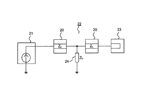
Figure 2 presents an example of detection device implementing according to
the invention. This device comprises at least one reflectometry system 21, or
reflectometer, and a heat-sensitive coaxial cable 22 capable of being
installed along a duct conveying hot air, the cable is represented in the
figure
by its characteristic impedance 20. The heat-sensitive coaxial cable is for
example of the type of that described previously. In all cases, it is
characterized by a modification of the dielectric or insulation properties of
the
material insulating the central conductor, or central core, and the peripheral
conductor, or shielding. This coaxial cable could be replaced by any two-wire
lines in which the two conductors are separated by an insulating material
whose insulation characteristics vary with temperature. The insulation is
characterized by a resistance whose value tends toward infinity at a
temperature corresponding to normal conditions, this value decreasing from
a given temperature to reach a very low resistance value, almost zero,
through the rising temperature.
The invention will nevertheless be described in the case of use of a coaxial
cable. The coaxial cable is not connected in a loop. In particular, one of its
CA 02969483 2017-06-01
ends is linked to the reflectometry system 21 and the other end is for
example open circuit 23, making it possible to reduce the length of cable,
which is a substantial advantage, particularly for an avionic application.
With
a device according to the invention it is in fact no longer necessary to use a
5 cable 22, or a line, connected in a loop. A loop configuration can
nevertheless be used, particularly to increase the location accuracy or to
ensure information redundancy.
This cable 22 is installed along the duct so as to react to a rise produced by
a
leak of hot air. It can be fixed to the duct or fixed to a support in
proximity to
the duct.
The method according to the invention is therefore based on the
reflectometry techniques for locating hot points due to a "bleed" leak. The
reflectometry system 21 used for example performs multicarrier reflectometry
measurements, called MCTDR, but any other type of reflectometry probe
signal may be suitable, provided that the bandwidth is matched to the length
of the cable 22. The injection signal for example observes at least the
following three conditions:
- the frequency band and the sampling of the signal are matched to the
length of the cable to ensure that the signal is not completely
attenuated, retaining a suitable location accuracy;
- the signal observes a condition of perfect harmlessness to the heat-
sensitive cable;
- the signal observes the standards applicable to the environment of a
device implementing the invention, for example EMC.
Advantageously, the MCTDR measurements allow a device according to the
invention to be superimposed on current detection systems, already installed
for example.
Multicarrier reflectometry measurements are notably described in the
document W02009/138391.
The materials used in the heat-sensitive cable are not as good conductors as
copper. The reflectometry signal will therefore undergo a relatively
significant
attenuation, which limits the range if retaining a good location accuracy is
desired. This point is not however very critical in as much as the sum of the
CA 02969483 2017-06-01
6
lengths of the heat-sensitive elements of the detection loops in the airplanes
rarely exceeds 20 meters.
To detect a leak, the device according to the invention uses the local
variation of insulation impedance of the cable 22 in line with the link, in
particular a reduction of the local value of the insulation impedance in the
time domain. In other words, as the air flow increases the temperature of the
hot spot situated at the level of the leak, a spot parallel impedance 24 of
non-
zero value appears between the central core and the shielding of the heat-
sensitive cable. The value Zh of this local impedance 24 becomes
increasingly low, until an almost clean short-circuit.
The reflectometry system 21 generates a source signal which is propagated
in the heat-sensitive cable 22. When it has arrived at the hot spot, a part of
the energy is reflected to the source, at the reflectometry system level,
while
the rest of the signal is transmitted to the end of the cable, at the open
circuit
23 level. The echo obtained in the absence of hot spot is denoted F, this
echo F being produced by the reflection of the reflectometry signal on the
open circuit 23.
By using Z, to denote the value of the characteristic impedance 20 of the
cable and Zn to denote the value of the insulation impedance 24 appearing at
the hot spot, the hot spot will modify the echo F into an echo r according to
the following relationship (1):
F'
2Z,ZhF ¨ 4.2(1 + F)
=
+ 4,2(1+0
In the absence of hot spot, Zn is infinite, so therefore F = , in fact:
2Z Zhl-
__________________________________________________ =F
2ZcZ,
In case of a total, clean short-circuit, Zn is equal to 0, F' = -1, in fact:
Z h 0 F' ¨> ¨1
Figure 3 illustrates the value of the echoes between these two extreme
values, and more particularly the trend of the echoes from the appearance of
CA 02969483 2017-06-01
7
a hot spot, in practice from the appearance of a leak in a duct provoking an
overheating. Figure 3 illustrates the trend of the echoes by a representation
of the trend of the reflectorgram of the carrier wave, the reflectogram being
the signal resulting from the reflectometry measurement.
A first curve 31 represents the echo received by the reflectometer 21 in the
case where there is no hot spot, Zh being infinite. A positive spike 30
corresponds to the reflection on the open circuit 23. A second curve 32
represents the echo in the case of the appearance of a hot spot. A negative
spike 39 appears whereas the positive spike 30 is reduced, corresponding to
the loss of reflected energy at the hot spot level. The distance to the hot
spot
is conventionally obtained from the speed of propagation of the reflectometry
signal and its echo along the line 22. The curves of figure 3 therefore
represent the amplitude of the echo received as a function of the distance.
The other curves 33, 34, 35 represent the trend of the echo received over
time, the negative spike 39 increasing negatively as a function of the
increasing heat, the positive spike decreasing accordingly.
The distance revealed by the negative spike 39 makes it possible to obtain
the location of the hot spot. Advantageously, the location accuracy can be
less than 1% of the total length of the cable 22.
The invention also and advantageously makes it possible to dispense with
local resistance trends independent of temperature, such as, for example,
contact resistance increases at certain junctions. In effect, these local
problems produce echoes which do not follow the trend of the echoes
illustrated by figure 3, echoes that are characteristic of the appearance of a
hot spot.
The cable can be open circuit as illustrated by figure 2 or form a loop. In
the
latter case, it is linked by its two ends to the reflectometer 21. In a loop
configuration, a complementary measurement can be performed at the other
end. A second reflectometry signal is thus sent from this other end to confirm
the location of the hot spot detected by the signal sent from the first end.
The
reliability of the information and its accuracy are thus advantageously
increased. It is advantageously possible, in this case, to use techniques of
D-MCTDR type which makes it possible to inject the signal by both ends at
the same time with no synchronization system.
CA 02969483 2017-06-01
8
The invention also has the advantage that it can be adapted to existing loops,
without their wiring being modified. It is sufficient to provide appropriate
connectors to link in particular the reflectometer to the loop and to be
superimposed on the detection system already present.
It is possible to calculate the value Zh of the insulation resistance from the
echoes received and deduce therefrom the temperature of the hot spot. To
this end, to simplify the calculations, it is possible to assume that there
are no
losses in the cable 22, the loop being open circuit 23. In this case, the
relationship (1) is simplified and a value of the echo F' provoked by the hot
spot is obtained that is a function only of Zh and of the characteristic
impedance Zc :
¨Z,
r= ______________________________________
2z, + Z,
Zh is deduced from this relationship i.e.:
Zh = (1 + F')121' (2)
Knowing the trend law of the insulation impedance Zh as a function of the
temperature, the value Tr, of the temperature at the hot spot is deduced
therefrom.
Figure 4 presents an example of processing implemented by a device
according to the invention advantageously making it possible to compensate
the slow drifts in the heat-sensitive performance levels of the cable 22, and
also to measure these drifts, these measurements being able to be used for
maintenance operations.
In a preliminary step, the reflectogram of the line, looped or open circuit,
is
recorded. This reflectogram is obtained from in-situ measurements, that is to
say with the line arranged along the duct to be monitored, installed
operationally. The recorded reflectogram has a profile of the type of the
curve
31 of figure 3 corresponding to the absence of hot spot and constitutes the
original profile or reference profile. This profile can be regularly measured
and compared to the reference profile to measure the slow drifts of the line.
These measurements can be used subsequently in maintenance to identify
CA 02969483 2017-06-01
9
the drifts and anticipate failings. The slow drifts can notably be due to the
aging of the cable or even to changes of season. In practice, a particular
echo corresponds to the reference profile, the measurements of the drift are
therefore made relative to this echo forming the initial reference.
The initial reference 41 is also used in operation phase as in the example
illustrated by figure 4 for an embedded application. In this operational
phase,
the invention makes it possible to discriminate the rapid drifts, due to a
temperature increase, from the slow drifts, while measuring the latter. The
device therefore retains the initial reference echo 41 to identify the slow
drifts
of the line and for example propose preventive maintenance.
To identify the rapid drifts, provoked by appearance of hot spots, the device
according to the invention uses a floating reference 42, this reference being
modified in time. This floating reference makes it possible in particular to
not
take account of the slow drifts and thus eliminates many sources of false
alarms. The device regularly emits signals to perform the reflectometry
measurements 43. After each signal emitted the echoes received are
measured and then compared 44 to the floating reference 42. If the
amplitude of the current echo measured is less than the floating reference,
another signal is emitted then another measurement is performed and
compared. When the amplitudes of a given number of successive echoes are
increasingly greater than the floating reference, according to the profile of
figure 3, that is to say that the difference relative to the reference
increases
over time, this is an information item indicating the presence of a hot spot.
The taking into account of several successive measurements to disregard
faults which would not be due to the appearance of hot spots. In an extreme
case, it is, however, possible to take this given number as equal to 1.
A calculation of location 45 of the change of insulation impedance Zn is then
performed according to the known rules of reflectometry, this location
indicating the point of appearance of the hot spot. In parallel, an alarm
signal
46 is generated. To confirm the appearance of the hot spot, several
successive measurements are for example made to check whether profiles of
the type of those of figure 3 are obtained. In effect, the trend of the
measurements should correspond to the appearance of a hot spot. As
indicated previously, in case of a loop connection of the line 22, a
CA 02969483 2017-06-01
complementary reflectometry measurement can be made at a second end.
Given the time constants involved, all these complementary measurements
can be performed without problems.
In parallel with the comparisons 44 of the current echoes with the floating
5 reference, measurements 47 of these echoes are performed with the initial
reference. These comparisons 47 can be performed at a lower rate than the
preceding ones 44. In effect, given that it involves measurement of slow
drifts, it is not necessary to perform comparisons according to short periods.
If the result of the comparison 47 between the amplitude of the current echo
10 and the initial reference is greater than a given threshold, an alert 48
is
generated in particular for preventive maintenance. This alert can be stored
or sent to a maintenance center. The value of the floating reference can be
modified following the result of this comparison. In particular, the new value
of the floating reference can be chosen to be greater than the amplitude of
the echo thus detected.
The invention has been described for the detection of leaks in air ducts,
particularly in aircraft. However, the invention can advantageously be applied
for the detection of hot spots in installations other than air ducts, making
it
possible to detect other causes of hot spots, for example beginnings of fire.
In this case, the line 22 runs through the installation to be monitored, the
run
being chosen in a way appropriate to the type of monitoring or protection that
is desired.
For avionics applications, a device according to the invention is not
necessarily embedded. It is in fact possible to use it in maintenance mode.