Note: Descriptions are shown in the official language in which they were submitted.
CA 02970307 2017-06-08
WO 2016/105870
PCMJS2015/062915
- 1 -
STRUCTURED ADSORBENT BEDS, METHODS OF
PRODUCING THE SAME AND USES THEREOF
FIELD
[0001] The present
invention relates to structured adsorbent beds for
purification of gas feedstreams and methods of making such structured
adsorbent
beds. The structured adsorbent beds comprise a substrate with a high cell
density and a coating on the substrate, wherein the coating comprises
adsorbent
particles and a binder.
BACKGROUND
[0002] Gas
separation is important in many industries for removing
undesirable contaminants from a gas stream and for achieving a desired gas
composition. For example, natural gas from many gas fields can contain
significant levels of H20, SO2, H,S, CO2, N2, mercaptans, and/or heavy
hydrocarbons that have to be removed to various degrees before the gas can be
transported to market. It is preferred that as much of the acid gases (e.g.,
H,S
and CO2) be removed from natural gas as possible to leave methane as the
recovered component. Small increases in recovery of methane can result in
significant improvements in process economics and also serve to prevent
unwanted resource loss. It is
desirable to recover more than 80 vol %,
particularly more than 90 vol %, of the methane when detrimental impurities
are
removed.
[0003]
Additionally, synthesis gas (syngas) typically requires removal and
separation of various components before it can be used in fuel, chemical and
power applications because all of these applications have a specification of
the
exact composition of the syngas required for the process. As produced, syngas
can contain at least CO and H2. Other molecular components in syngas can be
CA 02970307 2017-06-08
WO 2016/105870
PCT/US2015/062915
- 2 -
CH4, CO2, H7S, H20, N2, and combinations thereof. Minority (or trace)
components in the gas can include hydrocarbons, NH3, NOR, and the like, and
combinations thereof. In almost all applications, most of the H2S should
typically be removed from the syngas before it can be used, and, in many
applications, it can be desirable to remove much of the CO2.
[0004] Adsorptive gas separation techniques are common in various
industries using solid sorbent materials such as activated charcoal or a
porous
solid oxide such as alumina, silica-alumina, silica, or a crystalline zeolite.
Adsorptive separation may be achieved by equilibrium or kinetic mechanisms.
A large majority of processes operate through the equilibrium adsorption of
the
gas mixture where the adsorptive selectivity is primarily based upon
differential
equilibrium uptake of one or more species based on parameters such as pore
size
of the adsorbent. Kinetically based separation involves differences in the
diffusion rates of different components of the gas mixture and allows
different
species to be separated regardless of similar equilibrium adsorption
parameters.
[0005] Kinetically based separation processes may be operated as pressure
swing adsorption (PSA), temperature swing adsorption (TSA), partial pressure
swing or displacement purge adsorption (PPSA) or as hybrid processes
comprised of components of several of these processes. These swing adsorption
processes can be conducted with rapid cycles, in which case they are referred
to
as rapid cycle thermal swing adsorption (RCTSA), rapid cycle pressure swing
adsorption (RCPSA), and rapid cycle partial pressure swing or displacement
purge adsorption (RCPPSA) technologies, with the term "swing adsorption"
taken to include all of these processes and combinations of them.
[0006] Traditionally, adsorptive separation processes use packed beds of
adsorbent particulates. However, the traditional packed beds are not likely to
CA 02970307 2017-06-08
WO 2016/105870
PCT/US2015/062915
- 3 -
meet the very stringent requirements for natural gas cleanup. Alternatively, a
structured adsorbent bed can be utilized to adsorb certain gas species. The
structured adsorbent bed can be a monolith, either in the form of one single
block or in the form of extrudates with multiple channels or cells, such as a
honeycomb structured monolith. The use of adsorbent monoliths provides one
approach to designing an adsorbent bed that has low pressure drop, good flow
distribution, and low dispersion. Monoliths have very low flow tortuosity and
can also be engineered for almost any user specified void volume to meet a
specified pressure drop. Other monolith advantages include avoidance of bed
fluidization or lifting. In addition to gas separation processes, these types
of
monoliths have historically been employed as catalyst supports in automobile
catalytic converters, catalytic combustion, electrochemical reactors and
biochemical reactors.
[0007] In order to prepare the monoliths for use in gas separation
processes or
as catalyst supports, the cells are washcoated with layers of catalytic or
adsorbent coatings. The cell density of the monolith and the size of the
particles
in the coating have a significant effect on the ability to successfully coat
the cells
in the monolith to provide a structured adsorbent bed. It is known that
coating
difficulty increases as the cell density of the monolith increases (i.e., the
channel
size of the monolith decreases), as the size of the particles in the coating
increases over 2 11M, as the number of coatings increase and as substrate
porosity
decreases toward zero porosity. For example, Agrafiotis, C. et al. report that
the
size of the suspended particles affects the adhesion of the washcoat on the
substrate, namely particles with a diameter of less than 2 Jim have increased
adhesion to a monolith with a cell density of 400 cells per square inch (cpsi)
than
larger diameter particles. J. Mater. Sci. Lett., 18:1421-1424 (1999). Thus,
typically the monoliths used in practice have lower cell densities (e.g., 300-
900
cpsi), the coatings contain small particles (e.g., diameter less than 2 iAm)
and/or
CA 02970307 2017-06-08
WO 2016/105870
PCT/1JS2015/062915
- 4 -
the coating is applied in very thin layers (e.g., 1 jam to 10 jam). For
example,
while U.S. Patent No. 6,936,561 reports a coating layer thickness above 300
jam
on a ceramic honeycomb monolith, the monolith has a low cell density of about
45 cpsi. Similarly, U.S. Patent No. 7,560,154 reports a method of
manufacturing
a honeycomb structure with a coating particle size of 15 to 75 11M, but the
cell
density of the structure is 260 cpsi.
[0008] However, kinetic separation processes, specifically rapid cycle
kinetic
separation processes require structured adsorbent beds with ultra high cell
density (i.e., greater than 1000 cpsi) and thicker coating layers.
Furthermore,
larger particle sizes in the coating are desirable because further milling to
reduce
the particle size can be avoided, thereby avoiding potential fracturing of the
particles which can result in diminished capacity and activity. Therefore,
there
is a need to provide structured adsorbent beds with ultra high cell density as
well
as thicker coating layers and larger particles sizes in the coating.
SUMMARY
[0009] It has been found that a structured adsorbent bed for purification
of a
gas feedstream comprising a substrate having a high cell density (e.g.,
greater
than 1040 cpsi), and a coating on the substrate, wherein the coating comprises
large adsorbent particles (e.g., an average diameter greater than 20 jam) and
a
binder, can be achieved by pretreating the substrate prior to applying the
adsorbent particles and binder.
[0010] Thus, in one aspect, embodiments of the invention provide a
structured adsorbent bed for purification of a gas feedstream comprising: a
substrate having a cell density greater than 1040 cpsi; and a coating on the
substrate, wherein the coating comprises adsorbent particles and a binder.
CA 02970307 2017-06-08
WO 2016/105870
PCT/US2015/062915
- 5 -
[0011] In still another aspect, embodiments of the invention provide a
method
of preparing the structured adsorbent bed described herein, the method
comprising: pretreating the substrate; preparing an aqueous slurry comprising
the adsorbent particles and the binder; and applying the aqueous slurry to the
substrate to form the coating on the substrate.
[0012] In still another aspect, embodiments of the invention provide a gas
separation process comprising contacting a gas mixture containing at least one
contaminant with an adsorbent bed described herein.
[0013] Other embodiments, including particular aspects of the embodiments
summarized above, will be evident from the detailed description that follows.
BRIEF DESCRIPTION OF THE DRAWINGS
[0014] Figure 1 illustrates an example of the distances used for
determining
the axis ratio of an adsorbent particle in a scanning electron microscope
(SEM)
image.
[0015] Figures 2a and 2b illustrate SEM images for a 2700 cpsi ceramic
monolith.
[0016] Figure 3 illustrates a Leica Optical scope picture with 40 x
magnification of a 1440 cpsi 315 stainless steel monolith after 900 C
calcination.
[0017] Figures 4a and 4b illustrate a transmission electron microscopy
(TEM)
image and size analysis results showing average diameter of the binder, 25 nm
colloidal Sisa,.
CA 02970307 2017-06-08
WO 2016/105870
PCT/US2015/062915
- 6 -
[0018] Figures 5a and 5b illustrate TEM image and size analysis results
showing average diameter of the binder, 100 nm colloidal SiO2.
[0019] Figures 6a and 6b illustrate a TEM image and size analysis results
showing average diameter of the binder, string of pearls colloidal SiO2.
[0020] Figure 7 illustrates a Leica Optical scope picture (40 x
magnification)
of a 1440 cpsi metal monolith after 4 coatings with DDR (25-30 um) and SiO2
(100 mu).
[0021] Figure 8 illustrates an SEM image of a DDR (25-30 um) and SiO2
(100 nm) coating on a 1440 cpsi metal monolith and/or glass slide after 500 C
calcination.
[0022] Figure 9 provides photographs of the 25-2-2, 26-6-2, 26-7-3, 26-8-23
and 25-4-23 coupons with coating prior to integrity testing.
[0023] Figure 10 illustrates a 26-8-23C coupon before integrity testing
(top
photograph) and after integrity testing (bottom photograph).
[0024] Figure 11 illustrates a 25-4-23C coupon before integrity testing
(top
photograph) and after integrity testing (bottom photograph).
[0025] Figure 12 illustrates a 26-7-3C coupon before integrity testing (top
photograph) and after integrity testing (bottom photograph).
[0026] Figure 13 illustrates test button D before (left photograph) and
after
(right photograph) adsorptive kinetic separation (AKS) integrity testing.
CA 02970307 2017-06-08
WO 2016/105870
PCT/US2015/062915
- 7 -
[0027] Figure 14 illustrates weight of test button D as superficial gas
velocity
increases during AKS integrity test.
[0028] Figure 15 illustrates zero length chromatography (ZLC) results
comparing a DDR adsorbent (without binder) to SiO2 bound DDR samples with
a DDR:Sia, weight ratio of 85:15 w/w.
[0029] Figure 16 illustrates ZLC results comparing a DDR adsorbent
(without binder) to SiO2 bound DDR samples with a DDR:Si02 weight ratio of
90:10 w/w.
DETAILED DESCRIPTION
[0030] In various aspects of the invention, structured adsorbent beds,
methods of preparing the structured adsorbent beds and gas separation
processes
using the structured adsorbent beds are provided.
I. Definitions
[0031] To facilitate an understanding of the present invention, a number of
terms and phrases are defined below.
[0032] As used in the present disclosure and claims, the singular forms
"a,"
"an," and "the" include plural forms unless the context clearly dictates
otherwise.
[0033] Wherever embodiments are described herein with the language
"comprising," otherwise analogous embodiments described in terms of
"consisting of' and/or "consisting essentially of' are also provided.
CA 02970307 2017-06-08
WO 2016/105870
PCT/US2015/062915
- 8 -
[0034] The term "and/or" as used in a phrase such as "A and/or B" herein is
intended to include "A and B", "A or B", "A", and "B".
[0035] As used herein, the term "adsorption" includes physisorption,
chemisorption, and condensation onto a solid support and combinations thereof.
[0036] The term "monolith" refers to any three-dimensional material that
can
contain numerous parallel channels per square inch and can serve as a support
for adsorbents or catalysts, such as solid pieces of metal or ceramic
materials or
honeycomb structures. The term monolith is meant to be distinguished from a
collection of individual particles packed into a bed formation, in which the
end
product comprises individual particles.
[0037] As used herein, the term "average diameter" of the particle refers
to
the number average of the major axis and minor axis.
[0038] As used herein, the term "porosity" refers to a measure of the void
spaces in a material, and is measured herein as percent between zero and 100%.
[0039] As used herein, the term "macroporosity" refers to the percentage of
pores in a material that have a diameter greater than 50 nm.
[0040] As used herein, the term "microporous" refers to solid materials
having pores with a diameter less than 2 nm.
[0041] As used herein, the term "Si/A1 ratio" is defined as the molar ratio
of
silica to alumina of a zeolitic structure.
II. Structured Adsorbent Bed
CA 02970307 2017-06-08
WO 2016/105870
PCT/US2015/062915
- 9 -
[0042] In a first embodiment a structured adsorbent bed for purification of
a
gas feedstreem is provided comprising a substrate and a coating on the
substrate.
A. Substrate
[0043] As discussed above, substrates traditionally have a lower cell
density
because as cell density of the substrate increases and the channels in the bed
decrease in size, difficulty in coating the substrates increases. However,
substrates, such as monoliths, with higher cell density are provided herein.
In
various aspects, the substrate has a cell density of greater than or equal to
about
900 cpsi, greater than or equal to about 920 cpsi, greater than or equal to
about
940 cpsi, greater than or equal to about 960 cpsi, greater than or equal to
about
980 cpsi, greater than or equal to about 1,000 cpsi, greater than or equal to
about
1,020 cpsi, greater than or equal to about 1,040 cpsi, greater than or equal
to
about 1,060 cpsi, greater than or equal to about 1,080 cpsi, greater than or
equal
to about 1,100 cpsi, greater than or equal to about 1,120 cpsi, greater than
or
equal to about 1,140 cpsi, greater than or equal to about 1,160 cpsi, greater
than
or equal to about 1,180 cpsi, greater than or equal to about 1,200 cpsi,
greater
than or equal to about 1,220 cpsi, greater than or equal to about 1,240 cpsi,
greater than or equal to about 1,260 cpsi, greater than or equal to about
1,280
cpsi, greater than or equal to about 1,300 cpsi, greater than or equal to
about
1,320 cpsi, greater than or equal to about 1,340 cpsi, greater than or equal
to
about 1,360 cpsi, greater than or equal to about 1,380 cpsi, greater than or
equal
to about 1,400 cpsi, greater than or equal to about 1,420 cpsi, greater than
or
equal to about 1,440 cpsi, greater than or equal to about 1,460 cpsi, greater
than
or equal to about 1,480 cpsi, greater than or equal to about 1,500 cpsi,
greater
than or equal to about 1,520 cpsi, greater than or equal to about 1,640 cpsi,
greater than or equal to about 1,760 cpsi, greater than or equal to about
1,880
cpsi, greater than or equal to about 1,900 cpsi, greater than or equal to
about
1,920 cpsi, greater than or equal to about 1,940 cpsi, greater than or equal
to
CA 02970307 2017-06-08
WO 2016/105870
PCT/US2015/062915
- 10 -
about 1,960 cpsi, greater than or equal to about 1,980 cpsi, greater than or
equal
to about 2,000 cpsi, greater than or equal to about 2,100 cpsi, greater than
or
equal to about 2,200 cpsi, greater than or equal to about 2,300 cpsi, greater
than
or equal to about 2,400 cpsi, greater than or equal to about 2,500 cpsi,
greater
than or equal to about 2,600 cpsi, greater than or equal to about 2,700 cpsi,
greater than or equal to about 2,800 cpsi, greater than or equal to about
2,900
cpsi, greater than or equal to about 3,000 cpsi, greater than or equal to
about
3,100 cpsi, greater than or equal to about 3,200 cpsi, greater than or equal
to
about 3,300 cpsi, greater than or equal to about 3,400 cpsi, greater than or
equal
to about 3,500 cpsi, greater than or equal to about 3,600 cpsi, greater than
or
equal to about 3,700 cpsi, greater than or equal to about 3,800 cpsi, greater
than
or equal to about 3,900 cpsi, greater than or equal to about 4,000 cpsi,
greater
than or equal to about 4,100 cpsi, greater than or equal to about 4,200 cpsi,
greater than or equal to about 4,300 cpsi, greater than or equal to about
4,400
cpsi, greater than or equal to about 4,500 cpsi, greater than or equal to
about
4,600 cpsi, greater than or equal to about 4,700 cpsi, greater than or equal
to
about 4,800 cpsi, greater than or equal to about 4,900 cpsi, or greater than
or
equal to about 5,000 cpsi. Particularly, the substrate has a cell density
greater
than about 1,040 cpsi and greater than or equal to about 1,400 cpsi.
Additionally
or alternatively, the substrate has a cell density of less than or equal to
about 900
cpsi, less than or equal to about 920 cpsi, less than or equal to about 940
cpsi,
less than or equal to about 960 cpsi, less than or equal to about 980 cpsi,
less
than or equal to about 1,000 cpsi, less than or equal to about 1,020 cpsi,
less than
or equal to about 1,040 cpsi, less than or equal to about 1,060 cpsi, less
than or
equal to about 1,080 cpsi, less than or equal to about 1,100 cpsi, less than
or
equal to about 1,120 cpsi, less than or equal to about 1,140 cpsi, less than
or
equal to about 1,160 cpsi, less than or equal to about 1,180 cpsi, less than
or
equal to about 1,200 cpsi, less than or equal to about 1,220 cpsi, less than
or
equal to about 1,240 cpsi, less than or equal to about 1,260 cpsi, less than
or
CA 02970307 2017-06-08
WO 2016/105870
PCT/US2015/062915
- 11 -
equal to about 1,280 cpsi, less than or equal to about 1,300 cpsi, less than
or
equal to about 1,320 cpsi, less than or equal to about 1,340 cpsi, less than
or
equal to about 1,360 cpsi, less than or equal to about 1,380 cpsi, less than
or
equal to about 1,400 cpsi, less than or equal to about 1,420 cpsi, less than
or
equal to about 1,440 cpsi, less than or equal to about 1,460 cpsi, less than
or
equal to about 1,480 cpsi, less than or equal to about 1,500 cpsi, less than
or
equal to about 1,520 cpsi, less than or equal to about 1,640 cpsi, less than
or
equal to about 1,760 cpsi, less than or equal to about 1,880 cpsi, less than
or
equal to about 1,900 cpsi, less than or equal to about 1,920 cpsi, less than
or
equal to about 1,940 cpsi, less than or equal to about 1,960 cpsi, less than
or
equal to about 1,980 cpsi, less than or equal to about 2,000 cpsi, less than
or
equal to about 2,100 cpsi, less than or equal to about 2,200 cpsi, less than
or
equal to about 2,300 cpsi, less than or equal to about 2,400 cpsi, less than
or
equal to about 2,500 cpsi, less than or equal to about 2,600 cpsi, less than
or
equal to about 2,700 cpsi, less than or equal to about 2,800 cpsi, less than
or
equal to about 2,900 cpsi, less than or equal to about 3,000 cpsi, less than
or
equal to about 3,100 cpsi, less than or equal to about 3,200 cpsi, less than
or
equal to about 3,300 cpsi, less than or equal to about 3,400 cpsi, less than
or
equal to about 3,500 cpsi, less than or equal to about 3,600 cpsi, less than
or
equal to about 3,700 cpsi, less than or equal to about 3,800 cpsi, less than
or
equal to about 3,900 cpsi, less than or equal to about 4,000 cpsi, less than
or
equal to about 4,100 cpsi, less than or equal to about 4,200 cpsi, less than
or
equal to about 4,300 cpsi, less than or equal to about 4,400 cpsi, less than
or
equal to about 4,500 cpsi, less than or equal to about 4,600 cpsi, less than
or
equal to about 4,700 cpsi, less than or equal to about 4,800 cpsi, less than
or
equal to about 4,900 cpsi, or less than or equal to about 5,000 cpsi. Ranges
expressly disclosed include combinations of the above-enumerated upper and
lower limits, e.g., about 900 cpsi to about 5,000 cpsi, about 1,500 cpsi to
about
3,000 cpsi, about 1,500 cpsi to about 4,000 cpsi, about 1,400 cpsi to about
3,300
CA 02970307 2017-06-08
WO 2016/105870
PCT/US2015/062915
- 12 -
cpsi, etc. Particularly, the substrate has a cell density of about 1,500 cpsi
to
about 4,000 cpsi.
[0044] Exemplary channel geometries in the substrate include, but are not
limited to a trapezoidal geometry and a square geometry.
[0045] In various aspects, the substrate can be a porous solid. Exemplary
porous solids include, but are not limited to a metal oxide, a mixed-metal
oxide,
a ceramic, a zeolite and combinations thereof. Metal oxides that can be used
include, but are not limited to alumina, silica, zirconia and titania. An
example
of a suitable mixed-metal oxide ceramic includes cordierite. Examples of
suitable zeolites include, but are not limited to ZSM-5 and ZSM-58.
[0046] In various aspects, the substrate has a porosity of less than or
equal to
about 40%, less than or equal to about 35%, less than or equal to about 30%,
less
than or equal to about 25%, less than or equal to about 20%, less than or
equal to
about 15%, less than or equal to about 10%, less than or equal to about 9%,
less
than or equal to about 8%, less than or equal to about 7%, less than or equal
to
about 6%, less than or equal to about 5%, less than or equal to about 4%, less
than or equal to about 3%, less than or equal to about 2%, less than or equal
to
about 1% or less than or equal to about 0.5%. Particularly, the substrate has
a
porosity of less than or equal to about 30%. Additionally or alternatively,
the
substrate has a porosity of greater than or equal to about 40%, greater than
or
equal to about 35%, greater than or equal to about 30%, greater than or equal
to
about 25%, greater than or equal to about 20%, greater than or equal to about
15%, greater than or equal to about 10%, greater than or equal to about 9%,
greater than or equal to about 8%, greater than or equal to about 7%, greater
than
or equal to about 6%, greater than or equal to about 5%, greater than or equal
to
about 4%, greater than or equal to about 3%, greater than or equal to about
2%,
CA 02970307 2017-06-08
WO 2016/105870
PCT/1JS2015/062915
- 13 -
greater than or equal to about 1% or greater than or equal to about 0.5%.
Ranges
expressly disclosed include combinations of the above-enumerated upper and
lower limits, e.g., about 0.5% to about 40%, about 1% to about 10%, about 2%
to about 30%, etc.
[0047] Additionally or alternatively, the substrate can be a non-porous
solid
having a porosity of about 0.0%. Exemplary non-porous solids include, but are
not limited to a metal, a glass, and a plastic. The metal can comprise
stainless
steel and/or aluminum.
B. Coating
[0048] In various aspects, the coating can comprise adsorbent particles.
The
adsorbent particles can have an average diameter of greater than or equal to
about 1 jam, greater than or equal to about 2 [im, greater than or equal to
about 4
greater than or equal to about 6 1.im, greater than or equal to about 8 !Am,
greater than or equal to about 10 m, greater than or equal to about 12 m,
greater than or equal to about 14 Ittm, greater than or equal to about 16 in,
greater than or equal to about 18 m, greater than or equal to about 20 m,
greater than or equal to about 21 Ittm, greater than or equal to about 22 p.m,
greater than or equal to about 23 m, greater than or equal to about 24 m,
greater than or equal to about 25 Ittm, greater than or equal to about 26 in,
greater than or equal to about 27 Ittm, greater than or equal to about 28 m,
greater than or equal to about 29 jam, greater than or equal to about 30 !Am,
greater than or equal to about 32 Ittm, greater than or equal to about 34 m,
greater than or equal to about 36 jam, greater than or equal to about 38 !Am,
greater than or equal to about 40 Ittm, greater than or equal to about 42 m,
greater than or equal to about 44 jam, greater than or equal to about 46
greater than or equal to about 48 jam or greater than or equal to about 50 m.
Particularly, the adsorbent particles have an average diameter greater than
about
CA 02970307 2017-06-08
WO 2016/105870
PCT/US2015/062915
- 14 -
20 pm. Additionally or alternatively, the adsorbent particles can have an
average diameter of less than or equal to about 1 pm, less than or equal to
about
2 pm, less than or equal to about 4 pm, less than or equal to about 6 pm, less
than or equal to about 8 m, less than or equal to about 10 pm, less than or
equal
to about 12 pm, less than or equal to about 14 pm, less than or equal to about
16
m, less than or equal to about 18 m, less than or equal to about 20 m, less
than or equal to about 21 pm, less than or equal to about 22 pm, less than or
equal to about 23 m, less than or equal to about 24 pm, less than or equal to
about 25 pm, less than or equal to about 26 pm, less than or equal to about 27
pm, less than or equal to about 28 pm, less than or equal to about 29 pm, less
than or equal to about 30 pm, less than or equal to about 32 pm, less than or
equal to about 34 pm, less than or equal to about 36 pm, less than or equal to
about 38 pm, less than or equal to about 40 pm, less than or equal to about 42
pm, less than or equal to about 44 pm, less than or equal to about 46 m, less
than or equal to about 48 pm or less than or equal to about 50 pm. Ranges
expressly disclosed include combinations of the above-enumerated upper and
lower limits, e.g., about 1 pm to about 50 pm, about 2 pm to about 40 pm,
about 10 IIM to about 36 pm, etc. Particularly, the adsorbent particles can
have
an average diameter of about 2 filn to about 50 pm and/or about 20 pm to about
40 pm.
[0049] Additionally or alternatively, the adsorbent particles described
herein
can generally have a hexagonal disc shape where the particles have hexagonal
faces. The top and bottom hexagonal faces can generally correspond to larger
hexagonal faces, with a smaller depth dimension (roughly) perpendicular to the
top and bottom faces. The hexagonal disc shape of the adsorbent particles can
be seen in Figure 8.
CA 02970307 2017-06-08
WO 2016/105870
PCT/US2015/062915
- 15 -
[0050]
Additionally or alternatively, the adsorbent particles described herein
can generally have a rounded or circular disc shape with top and bottom
rounded
or circular disc faces. The depth dimension for the rounded discs can be
smaller
than the lateral dimension of the rounded faces of the disc.
[0051] One way to
characterize the difference between the hexagonal disc
shape and the rounded disc shape can be based on the difference between the
vertex-to-vertex distance and the edge-to-edge distance in a hexagonal face of
a
crystal. To perform this type of characterization, an initial step can be to
identify
the correct face(s) of the particle for perfon-ning the characterization. For
a
hexagonal disc particle, the combination of a vertex-to-vertex line and an
edge-to-edge line can roughly define a plane. The dimension perpendicular to
this plane can then correspond to the depth of the crystal. For the hexagonal
disc
shape, this depth dimension can generally be shorter than either the vertex-to-
vertex distance or the edge-to-edge distance. If the depth distance is longer
than
either of the other two distances, then either a different hexagonal face
should be
selected for this calculation, or the crystal may not correspond to a
hexagonal
disc shape or round disc shape. After determining that the correct type of
hexagonal (or rounded) face has been selected for characterizing the crystal,
the
vertex-to-vertex distance and the edge-to-edge distance for the hexagonal face
can be compared in order to calculate an axis ratio.
Additionally or
alternatively, the adsorbent particles described herein can be a prismatic
shape.
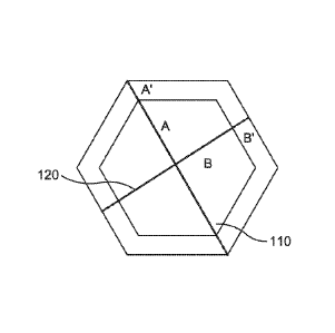
[0052] Figure 1
shows a schematic example of this type of calculation. In
Figure 1, line 110 corresponds to the vertex-to-vertex distance for a hexagon.
Line 120 corresponds to the edge-to-edge distance. For a hexagonal face with
well defined edges and vertices, the vertex-to-vertex distance, by definition,
is
typically larger than the edge-to-edge distance. As the angles and edges of
the
hexagon become smoothed toward forming a circle, to the degree that the
CA 02970307 2017-06-08
WO 2016/105870
PCT/US2015/062915
- 16 -
vertices and edges can still be identified, the vertex-to-vertex distance and
the
edge-to-edge distance can become increasingly closer. In the limiting case of
a
circle, the axis ratio of vertex-to-vertex distance and edge-to-edge distance
becomes 1, with the caveat that the location of a "vertex" and an "edge" in
the
limiting case may be somewhat arbitrary.
[0053] For adsorbent particles of the type shown in Figure 8, the ratio of
vertex-to-vertex distance versus edge-to-edge distance can be determined based
on measuring distances in an SEM micrograph. The adsorbent particles shown
in Figure 8 can be used herein in the coating and the axis ratio of the vertex-
to-vertex distance versus the edge-to-edge distance was observed to be at
least
about 1.15, such as at least about 1.2.
[0054] The characterization of the rounded disc shape particles can be
performed in a similar manner. The depth dimension can be identified in
relation to the rounded (approaching circular) face(s) of the crystal. In some
embodiments, a ratio of the depth dimension to the edge-to-edge distance can
be
about 0.9 or less, e.g., about 0.85 or less. In such embodiments, particles
with a
ratio of depth dimension to edge-to-edge distance of greater than about 0.95
were identified to correspond to a roughly spherical morphology. The rounded
face of the rounded discs can then be characterized using the axis ratio.
Additionally or alternatively, the round disc particles can have an axis ratio
of
the vertex-to-vertex distance versus edge-to-edge distance of about 1.1 or
less,
e.g., about 1.05 or less, or a still lower value that can approach the
limiting axis
ratio value of 1Ø
[0055] Additionally or alternatively, the adsorbent particles comprise a
microporous material, such as a zeolite. The zeolite can have a Si/A1 ratio of
at
least about 200:1, at least about 300:1, at least about 400:1, at least about
500:1,
- 17 -
at least about 600:1, at least about 700:1, at least about 800:1, at least
about 900:1
or at least about 1,000:1. Particularly, the zeolite can have a Si/A1 ratio of
about
600:1. Examples of suitable zeolites include, but are not limited to the
following
zeolite frameworks: CDO, FAU, MFI, DOH, DDR and combinations thereof.
Particularly, the zeolite can be DDR. Examples of DDR framework zeolites
include, but are not limited to Sigma-1, ZSM-58 and SSZ-28. A person of
ordinary skill in the art knows how to make the aforementioned zeolites. For
example, see the references provided in the International Zeolite
Association's
database of zeolite structures found at vvww.iza-structure.org/databases.
Particularly, the DDR framework zeolite can be ZSM-58. For example, ZSM-58
can be formed according to the methods described in U.S. Patent Application
Publication No. 2014/0161717.
Additionally or alternatively, the DDR
framework zeolite can include DDR frameworks formed according to the methods
described in U.S. Provisional Patent Application Serial No. 62/082,210.
[0056]
Additionally or alternatively, the coating can also comprise a binder.
The binder particles are capable of binding the adsorbent particles together
to
form an aggregate of binder particles and adsorbent particles in the coating.
The
binder can comprise particles having an average diameter of greater than or
equal to about 10 nm, greater than or equal to about 15 nm, greater than or
equal
to about 20 nm, greater than or equal to about 25 nm, greater than or equal to
about 30 nm, greater than or equal to about 35 nm, greater than or equal to
about
45 nm, greater than or equal to about 50 nm, greater than or equal to about 55
nm, greater than or equal to about 60 nm, greater than or equal to about 65
nm,
greater than or equal to about 70 nm, greater than or equal to about 75 nm,
greater than or equal to about 80 nm, greater than or equal to about 85 nm,
greater than or equal to about 90 nm, greater than or equal to about 95 nm,
CA 2970307 2018-10-24
CA 02970307 2017-06-08
WO 2016/105870
PCT/US2015/062915
- 18 -
greater than or equal to about 100 nm, greater than or equal to about 110 nm,
greater than or equal to about 120 nm, greater than or equal to about 130 nm,
greater than or equal to about 140 nm, greater than or equal to about 150 nm,
greater than or equal to about 160 nm, greater than or equal to about 170 nm,
greater than or equal to about 180 nm, greater than or equal to about 190 nm,
greater than or equal to about 200 nm, greater than or equal to about 210 nm,
greater than or equal to about 220 nm, greater than or equal to about 230 nm,
greater than or equal to about 240 nm or greater than or equal to about 250
nm.
Additionally or alternatively, the binder can comprise particles can have an
average diameter of less than or equal to about 10 nm, less than or equal to
about
15 nm, less than or equal to about 20 nm, less than or equal to about 25 rim,
less
than or equal to about 30 nm, less than or equal to about 35 nm, less than or
equal to about 45 nm, less than or equal to about 50 urn, less than or equal
to
about 55 nm, less than or equal to about 60 nm, less than or equal to about 65
nm, less than or equal to about 70 nm, less than or equal to about 75 nm, less
than or equal to about 80 nm, less than or equal to about 85 nm, less than or
equal to about 90 nm, less than or equal to about 95 urn, less than or equal
to
about 100 nm, less than or equal to about 110 nm, less than or equal to about
120
nm, less than or equal to about 130 nm, less than or equal to about 140 nm,
less
than or equal to about 150 nm, less than or equal to about 160 nm, less than
or
equal to about 170 nm, less than or equal to about 180 nm, less than or equal
to
about 190 nm, less than or equal to about 200 nm, less than or equal to about
210
nm, less than or equal to about 220 nm, less than or equal to about 230 nm,
less
than or equal to about 240 nm or less than or equal to about 250 nm. Ranges
expressly disclosed include combinations of the above-enumerated upper and
lower limits, e.g., about 10 nm to about 250 nm, about 25 nm to about 200 nm,
about 100 nm to about 200 nm, etc. Particularly, the binder particles can have
an
average diameter of about 100 nm to about 200 nm.
CA 02970307 2017-06-08
WO 2016/105870
PCT/US2015/062915
- 19 -
[0057] Additionally or alternatively, the binder is basic. The binder can
have
a pH of greater than or equal to about 7, greater than or equal to about 7.5,
greater than or equal to about 8, greater than or equal to about 8.5, greater
than
or equal to about 9, greater than or equal to about 9.5, greater than or equal
to
about 10, greater than or equal to about 10.5, greater than or equal to about
11,
greater than or equal to about 11.5, greater than or equal to about 12,
greater than
or equal to about 12.5, greater than or equal to about 13, greater than or
equal to
about 13.5 or greater than or equal to about 14. Particularly, the binder can
have
a pH greater than about 7, particularly about 10. Additionally or
alternatively,
the binder has a pH of less than or equal to about 7, less than or equal to
about
7.5, less than or equal to about 8, less than or equal to about 8.5, less than
or
equal to about 9, less than or equal to about 9.5, less than or equal to about
10,
less than or equal to about 10.5, less than or equal to about 11, less than or
equal
to about 11.5, less than or equal to about 12, less than or equal to about
12.5, less
than or equal to about 13, less than or equal to about 13.5 or less than or
equal to
about 14. Ranges expressly disclosed include combinations of the above-
enumerated upper and lower limits, e.g., about 7 to about 14, about 10 to
about
12, about 11 to about 13.5, about 11 to about 12.5, etc. Particularly, the pH
can
be from about 7 to about 11.
[0058] Exemplary materials suitable for use as the binder include but are
not
limited to silica (SiO2) and alumina (A1203). Particularly, the binder can
comprise SiO2.
[0059] Additionally or alternatively, the coating can be present on the
substrate in a thickness of greater than or equal to about 20 !Am, greater
than or
equal to about 30 1.1m, greater than or equal to about 40 jim, greater than or
equal
to about 50 !Am, greater than or equal to about 60 11M, greater than or equal
to
about 70 1.1m, greater than or equal to about 80 jim, greater than or equal to
about
CA 02970307 2017-06-08
WO 2016/105870
PCT/US2015/062915
- 20 -
90 gm, greater than or equal to about 100 gm, greater than or equal to about
110
gm, greater than or equal to about 120 gm, greater than or equal to about 130
gm, greater than or equal to about 140 gm, greater than or equal to about 150
gm, greater than or equal to about 160 gm, greater than or equal to about 170
gm, greater than or equal to about 180 gm, greater than or equal to about 190
gm, greater than or equal to about 200 gm, greater than or equal to about 210
gm, greater than or equal to about 220 gm, greater than or equal to about 230
gm, greater than or equal to about 240 11M, greater than or equal to about 250
gm, greater than or equal to about 260 gm, greater than or equal to about 270
gm, greater than or equal to about 280 11M, greater than or equal to about 290
gm, or greater than or equal to about 300 gm. Particularly, the coating can be
present on the substrate in a thickness of greater than or equal to about 100
gm.
Additionally or alternatively, the coating can be present on the substrate in
a
thickness of less than or equal to about 20 gm, less than or equal to about 30
gm,
less than or equal to about 40 gm, less than or equal to about 50 gm, less
than or
equal to about 60 gm, less than or equal to about 70 11M, less than or equal
to
about 80 gm, less than or equal to about 90 gm, less than or equal to about
100
gm, less than or equal to about 110 gm, less than or equal to about 120 gm,
less
than or equal to about 130 gm, less than or equal to about 140 gm, less than
or
equal to about 150 gm, less than or equal to about 160 gm, less than or equal
to
about 170 gm, less than or equal to about 180 gm, less than or equal to about
190 gm, less than or equal to about 200 gm, less than or equal to about 210
gm,
less than or equal to about 220 gm, less than or equal to about 230 gm, less
than
or equal to about 240 gm, less than or equal to about 250 gm, less than or
equal
to about 260 gm, less than or equal to about 270 gm, less than or equal to
about
280 gm, less than or equal to about 290 gm, or less than or equal to about 300
gm. Ranges expressly disclosed include combinations of the above-enumerated
upper and lower limits, e.g., about 20 gm to about 300 gm, about 30 gm to
about
CA 02970307 2017-06-08
WO 2016/105870
PCT/US2015/062915
- 21 -
200 gm, about 50 gm to about 100 gm, etc. Particularly, the coating on the
substrate can have a thickness of about 30 gm to about 200 gm.
[0060] Additionally or alternatively, the coating can comprise one or more
layers of adsorbent particles and binder particles. The coating can comprise
two
or more layers, three or more layers, four or more layers, five or more
layers, six
or more layers, seven or more layers, eight or more layers, nine or more
layers,
or ten or more layers of adsorbent particles and binder particles.
Additionally or
alternatively, the coating can comprise two or fewer layers, three or fewer
layers,
four or fewer layers, five or fewer layers, six or fewer layers, seven or
fewer
layers, eight or fewer layers, nine or fewer layers, or ten or fewer layers of
adsorbent particles and binder particles. Ranges expressly disclosed include
combinations of the above-enumerated upper and lower limits, e.g., one to ten
layers, two to eight layers, three to seven layers, etc.
[0061] Additionally or alternatively, the coating on the substrate can have
a
macroporosity of at least about 5%, at least about 10%, at least about 15%, at
least about 20%, at least about 25%, at least about 30%, at least about 35%,
at
least about 40%, at least about 45% or at least about 50%. The coating on the
substrate can have a macroporosity of less than about 5%, less than about 10%,
less than about 15%, less than about 20%, less than about 25%, less than about
30%, less than about 35%, less than about 40%, less than about 45% or less
than
about 50%. Ranges expressly disclosed include combinations of the above-
enumerated upper and lower limits, e.g., about 5% to about 50%, about 10% to
about 40%, about 20% to about 35%, etc. Particularly, the coating on the
substrate can have a macroporosity of about 10% to about 40%.
CA 02970307 2017-06-08
WO 2016/105870
PCT/US2015/062915
- 22 -
C. Primer Layer
[0062] Additionally or alternatively, the adsorbent bed may further
comprise
a primer layer on the substrate. The primer layer can be present between the
substrate and the coating. The primer layer can increase surface roughness of
the substrate and/or provide a surface more similar in composition to the
adsorbent particles in the coating for increased adhesion and improved bonding
of the coating to the substrate. Additionally, when the substrate is a metal,
the
primer layer can reduce exposure of potentially reactive species on the metal
surface and also diminish thermal expansion differences between the metal
surface and the coating. The primer layer can be a zirconium-containing layer.
Particularly, the zirconium-containing layer can comprise zirconium oxide,
zirconium silicate or a combination thereof.
III. Methods of Preparing the Structured Adsorbent Bed
[0063] In various aspects, a method of preparing a structured adsorbent bed
described herein is provided. The method can comprise pretreating the
substrate, preparing an aqueous slurry comprising the adsorbent particles and
the
binder and applying the aqueous slurry to the substrate to form the coating on
the
substrate.
[0064] Additionally or alternatively, pretreating the substrate can
comprise
applying a primer layer, such as the zirconium-containing layer described
herein.
Additionally or alternatively, the substrate can be cleaned prior to
application of
the primer layer.
[0065] Additionally or alternatively, pretreating the substrate can
comprise
heating the substrate and applying a primer layer, such as the zirconium-
containing layer described herein. When the substrate is a metal having no
porosity, heating the substrate prior to application of the primer layer
results in a
CA 02970307 2017-06-08
WO 2016/105870
PCT/US2015/062915
- 23 -
micron-thin metal oxide skin, which roughens the metal surface and creates
anchoring sites on the metal surface thereby improving adhesion and bonding of
the coating. In pretreating the substrate, the substrate can be heated at a
temperature of greater than or equal to about 500 C, greater than or equal to
about 550 C, greater than or equal to about 600 C, greater than or equal to
about
650 C, greater than or equal to about 700 C, greater than or equal to about
750 C, greater than or equal to about 800 C, greater than or equal to about
850 C, greater than or equal to about 900 C, greater than or equal to about
950 C, greater than or equal to about 1,000 C, greater than or equal to about
1,050 C, greater than or equal to about 1,100 C, greater than or equal to
about
1,150 C, greater than or equal to about 1,200 C, greater than or equal to
about
1,250 C, or greater than or equal to about 1,300 C.
Additionally or
alternatively, the substrate can be heated at a temperature of less than or
equal to
about 500 C, less than or equal to about 550 C, less than or equal to about
600 C, less than or equal to about 650 C, less than or equal to about 700 C,
less
than or equal to about 750 C, less than or equal to about 800 C, less than or
equal to about 850 C, less than or equal to about 900 C, less than or equal to
about 950 C, less than or equal to about 1,000 C, less than or equal to about
1,050 C, less than or equal to about 1,100 C, less than or equal to about
1,150 C, less than or equal to about 1,200 C, less than or equal to about
1,250 C, or less than or equal to about 1,300 C. Ranges expressly disclosed
include combinations of the above-enumerated upper and lower limits, e.g.,
about 500 C to about 1,300 C, about 600 C to about 1,100 C, about 900 C to
about 1050 C, etc. The substrate can be heated at a temperature of about 600 C
to about 1,100 C, particularly about 900 C.
[0066]
Additionally or alternatively, the substrate can be pre-treated by
heating the substrate for at least about 1 hour, at least about 2 hours, at
least
about 3 hours, at least about 4 hours, at least about 5 hours, at least about
6
CA 02970307 2017-06-08
WO 2016/105870
PCT/US2015/062915
- 24 -
hours, at least about 7 hours, at least about 8 hours, at least about 9 hours
or at
least about 10 hours, particularly at least about 6 hours. Alternatively or
additionally, the substrate can be heated for less than about 1 hour, less
than
about 2 hours, less than about 3 hours, less than about 4 hours, less than
about 5
hours, less than about 6 hours, less than about 7 hours, less than about 8
hours,
less than about 9 hours or less than about 10 hours. Ranges expressly
disclosed
include combinations of the above-enumerated upper and lower limits, e.g.,
about 1 hour to about 10 hours, about 1 hour to about 2 hours, about 2 hours
to
about 6 hours, etc.
[0067] Additionally or alternatively, the aqueous slurry can comprise the
adsorbent particles and the binder, both as described herein, in a weight
ratio
from about 70:30 w/w to about 90:10 w/w. Particularly, the weight ratio of
adsorbent particles to binder in the aqueous slurry can be about 80:20 w/w or
about 90:10 w/w. Particularly, the binder in the aqueous slurry can be SiO2.
Additionally or alternatively, the aqueous slurry can include viscosity
modifiers,
water and/or dispersants.
[0068] Coating adhesion, particle cohesion and uniformity depend on slurry
properties. Further, the size of the suspended particles has a great influence
on
the stability of the suspension and adhesion to the substrate. In one aspect,
the
adsorbent particles in the slurry have an average diameter of greater than or
equal to about 25 irn. Additionally or alternatively, the binder particles in
the
slurry have an average diameter of from about 100 nm to about 200 nm. The
aqueous slurry as described herein can be stable for many hours, for example
about 5, about 10, about 15, about 20, about 25, about 30 hours if stirred and
minutes if not stirred. Further, the aqueous slurry can have a pH of about 7
to
about 10 and an approximate viscosity of 14.4 cP. Additionally or
alternatively,
CA 02970307 2017-06-08
WO 2016/105870
PCT/US2015/062915
- 25 -
the aqueous slurry can also include organic additives for controlling rheology
of
the slurry and/or to act as temporary binding aids.
[0069] Additionally or alternatively, the aqueous slurry can be applied to
the
substrate by dip coating techniques, pulling the slurry into the substrate
with a
vacuum and/or pumping the slurry into the substrate. Multiple coatings of the
aqueous slurry can be applied to the substrate, for example, at least one
coating,
at least two coatings, at least three coatings, at least four coatings, at
least five
coatings, at least six coatings, at least seven coatings, at least eight
coatings, at
least nine coatings or at least ten coatings.
[0070] Additionally or alternatively, the method further comprises removing
excess coating from the coated substrate, drying the coated substrate and/or
heating the coated substrate.
[0071] Removing the excess coating in a high cell density substrate (e.g.,
monoliths) can be difficult due to the high capillary forces within the cells
as
result of the smaller channel diameter (e.g., 400 lim) of the high cell
density
substrates. To remove excess coating from the channels in the substrate, the
pressure drop across the substrate must be greater than the capillary force
through the channel. Thus, in one aspect, the excess coating can be removed
from the substrate by flowing a gas, such as nitrogen, through the coated
substrate at a rate greater than or equal to about 100 L/min, greater than or
equal
to about 150 L/min, greater than or equal to about 200 L/min, or greater than
or
equal to about 250 L/min. Particularly, the gas can be flowed through the
substrate at a rate greater than or equal to about 100 L/min. Additionally or
alternatively, the gas can be flowed through the substrate at a rate lesser
than or
equal to about 100 L/min, lesser than or equal to about 150 L/min, lesser than
or
equal to about 200 L/min, or lesser than or equal to about 250 L/min. Ranges
CA 02970307 2017-06-08
WO 2016/105870
PCT/US2015/062915
- 26 -
expressly disclosed include combinations of the above-enumerated upper and
lower limits, e.g., about 100 L/min to about 250 L/min, about 100 L/min to
about 200 L/min, etc.
[0072] Additionally or alternatively, drying the coated substrate can
comprise
flash drying the coated substrate. The gas flowed through the substrate at a
high
flow rate to remove excess coating can result in rapid evaporative cooling of
the
slurry in the channels. This can lead to slower water evaporation and drying
of
the slurry, which can contribute to "bridging," resulting in channels being
blocked by unstable, mobile slurry particles bridging the cell diameter in the
monoliths and drying into plugs. Flash drying the coated substrate may
stabilize
the coating films and prevent "bridging" and size segregation of the zeolite
and
binder particles upon vertical standing. The flash drying can comprise heating
a
gas purge, such as the same gas used to remove the excess coating, to about
40 C, about 45 C, about 50 C, about 55 C, about 60 C, about 65 C or about
70 C, particularly between about 50 C and about 60 C. The heated gas purge
can be flowed through the coated substrate at a rate of at least about 100
L/min,
at least about 150 L/min, at least about 200 L/min, or at least about 250
L/min.
Particularly, the heated purge gas can be flowed through the substrate at a
rate of
at least about 100 L/min. Additionally or alternatively, the heated gas purge
can
be flowed through the coated substrate at a rate of no greater than about 100
L/min, no greater than about 150 L/min, no greater than about 200 L/min, or no
greater than about 250 L/min. Ranges expressly disclosed include combinations
of the above-enumerated upper and lower limits, e.g., about 100 L/min to about
250 L/min, about 100 L/min to about 200 L/min, etc.
[0073] Additionally or alternatively, the method further comprises
calcining
the coated substrate, which optionally, can be performed after the coated
substrate is dried. The calcining can be performed in air. The calcining can
be
CA 02970307 2017-06-08
WO 2016/105870
PCT/US2015/062915
- 27 -
performed at a temperature suitable for degrading and/or removing
substantially
all of the volatile organic components and water in the structured adsorbent
bed,
for example, at least about 300 C, at least about 350 C, at least about 400 C,
at
least about 450 C, about 500 C, at least about 550 C or at least about 600 C.
Additionally or alternatively, the calcining can be performed at a temperature
of
less than about 300 C, less than about 350 C, less than about 400 C, less than
about 450 C, less than about 500 C, less than about 550 C or less than about
600 C. Ranges expressly disclosed include combinations of the above-
enumerated upper and lower limits, e.g., about 300 C to about 600 C, about
350 C to about 450 C, about 300 C to about 500 C, etc. Particularly, the
calcining is performed at a temperature of about 500 C, optionally using a
heating ramp, such as: a) drying at about 120 C for about 8 hours; b)
increasing
the temperature to about 500 C over about 4 hours; c) holding at about 500 C
for about 2 hours; and d) cooling to about 120 C over about 2 hours.
IV. Gas Separation Processes
[0074] In various aspects, a gas separation process is provided herein. The
gas separation process comprises contacting a gas mixture containing at least
one contaminant with a structured adsorbent bed as described herein.
[0075] In various aspects, the gas separation process can be achieved by
swing adsorption processes, such as pressure swing adsorption (PSA) and
temperature swing adsorption (TSA). All swing adsorption processes have an
adsorption step in which a feed mixture (typically in the gas phase) is flowed
over an adsorbent that preferentially adsorbs a more readily adsorbed
component
relative to a less readily adsorbed component. A component may be more
readily adsorbed because of kinetic or equilibrium properties of the
adsorbent.
The adsorbent can typically be contained in a contactor that is part of the
swing
adsorption unit. The contactor can typically contain an engineered structured
CA 02970307 2017-06-08
WO 2016/105870
PCT/US2015/062915
- 28 -
adsorbent bed or a particulate adsorbent bed. The bed can contain the
adsorbent
and other materials such as other adsorbents, mesopore filling materials,
and/or
inert materials used to mitigate temperature excursions from the heat of
adsorption and desorption. Other components in the swing adsorption unit can
include, but are not necessarily limited to, valves, piping, tanks, and other
contactors.
[0076] PSA
processes rely on the fact that gases under pressure tend to be
adsorbed within the pore structure of the adsorbent materials. Typically, the
higher the pressure, the greater the amount of targeted gas component that
will
be adsorbed. When the pressure is reduced, the adsorbed targeted component is
typically released, or desorbed. PSA processes can be used to separate gases
of
a gas mixture, because different gases tend to fill the pores or free volume
of the
adsorbent to different extents due to either the equilibrium or kinetic
properties
of the adsorbent. In many
important applications, to be described as
"equilibrium-controlled" processes, the adsorptive selectivity is primarily
based
upon differential equilibrium uptake of the first and second components. In
another important class of applications, to be described as "kinetic-
controlled"
processes, the adsorptive selectivity is primarily based upon the differential
rates
of uptake of the first and second components.
[0077] If a gas
mixture, such as natural gas, is passed under pressure through
a vessel containing a polymeric or microporous adsorbent that is more
selective
towards carbon dioxide than it is for methane, at least a portion of the
carbon
dioxide can be selectively adsorbed by the adsorbent, and the gas exiting the
vessel can be enriched in methane. When the adsorbent reaches the end of its
capacity to adsorb carbon dioxide, it can be regenerated by reducing the
pressure, thereby releasing the adsorbed carbon dioxide. The adsorbent can
then
typically purged and repressurized and ready for another adsorption cycle.
- 29 -
[0078] TSA processes also rely on the fact that gases under pressure
tend to be
adsorbed within the pore structure of the adsorbent materials. When the
temperature of the adsorbent is increased, the adsorbed gas is typically
released, or
desorbed. By cyclically swinging the temperature of adsorbent beds, TSA
processes can be used to separate gases in a mixture when used with an
adsorbent
selective for one or more of the components in a gas mixture. Partial pressure
purge
displacement (PPSA) swing adsorption processes regenerate the adsorbent with a
purge. Rapid cycle (RC) swing adsorption processes complete the adsorption
step
of a swing adsorption process in a short amount of time. For kinetically
selective
adsorbents, it can be preferable to use a rapid cycle swing adsorption
process. If
the cycle time becomes too long, the kinetic selectivity can be lost. These
swing
adsorption protocols can be performed separately or in combinations. Examples
of
processes that can be used herein either separately or in combination are PSA,
TSA,
pressure temperature swing adsorption (PTSA), partial purge displacement swing
adsorption (PPSA), PPTSA, rapid cycle PSA (RCPSA), RCTSA, vacuum pressure
swing adsorption (VPSA), RCPPSA and rapid cycle pressure-temperature swing
adsorption (RCPTSA).
[0079] In PSA processes, a feed gas mixture containing the first and
second
gas components is separated by cyclic variations of pressure coordinated with
cyclic reversals of flow direction in a flow path contacting a fixed bed of
the
adsorbent material in an adsorber vessel. In the case of TSA or PPSA
processes,
cyclic variations of temperature and/or partial pressure of the gas components
may be coordinated with gas flow through a flow path to perform a separation.
The process in any specific PSA application operates at a cyclic frequency
characterized by its period, and over a pressure envelope between a first
relatively higher pressure and a second relatively lower pressure. Separation
in
PSA is achieved by coordinating the pressure variations with the flow pattern
CA 2970307 2018-10-24
CA 02970307 2017-06-08
WO 2016/105870
PCT/US2015/062915
- 30 -
within the flow path, so that the gas mixture in the flow path is enriched in
the
second component (owing to preferential adsorptive uptake of the first
component in the adsorbent material) when flowing in a first direction in the
flow path, while the gas mixture is enriched in the first component (which has
been desorbed by the adsorbent material) when flowing in the opposite
direction
in the flow path. In order to achieve separation performance objectives (i.e.
product gas purity, recovery and productivity), process parameters and
operating
conditions should be designed to achieve a sufficiently high adsorptive
selectivity of the first and second components over the adsorbent material, at
the
cyclic frequency and within the pressure envelope.
[0080] Swing adsorption processes can be applied to remove a variety of
target gases, also referred to as a "contaminant gas" from a wide variety of
gas
mixtures. The "light component" as utilized herein is taken to be the species
or
molecular component(s) not preferentially taken up by the adsorbent in the
adsorption step of the process. Conversely, the "heavy component" as utilized
herein is taken to be the species or molecular component(s) preferentially
taken
up by the adsorbent in the adsorption step of the process.
[0081] An example of a gas mixture that can be separated in the methods
described herein is a gas mixture comprising CH4, such as a natural gas
stream.
A gas mixture comprising CH4 can contain significant levels of contaminants
such as H20, H2S, CO2, N2, mercaptans, and/or heavy hydrocarbons.
Additionally or alternatively, the gas mixture can comprise NOx and/or SOx
species as contaminants, such as a waste gas stream, a flue gas stream and a
wet
gas stream. As used herein, the terms "NO,," and "NOx species" refers to the
various oxides of nitrogen that may be present in waste gas, such as waste gas
from combustion processes. The terms refer to all of the various oxides of
nitrogen including, but not limited to, nitric oxide (NO), nitrogen dioxide
(NO2),
-31 -
nitrogen peroxide (N20), nitrogen pentoxide (N205), and mixtures thereof. As
used herein, the terms "SO,," and "SOx species" refers to various oxides of
sulfur
that may be present in waste gas, such as waste gas from combustion processes.
The terms refer to all of the various oxides of sulfur including, but not
limited to,
SO, SO2, SO3, SO4, S702 and S602. Thus, examples of contaminants include, but
are not limited to H20, 112S, CO2, N2, mercaptans, heavy hydrocarbons, NOx
and/or Sa, species.
[0082] In the practice of the present invention, it may be desirable to
operate
with a multiplicity of structured adsorbent beds, with several coupled in a
heating/cooling operation and others involved in adsorption (and/or
desorption).
In such an operation, the adsorbent bed can be substantially cooled by a
circulating
heat transfer medium before it is switched into service for adsorption. One
advantage of such an operation can be that the thermal energy used to swing
the
bed is retained in the heat transfer medium. If adsorption were to proceed
simultaneously with cooling, then a substantial part of the heat in the bed
could
be lost to the adsorbate-free feed, and a higher heat load could be needed to
restore
the high temperature of the heat transfer medium.
[0083] Adsorptive kinetic separation (AKS) processes, as described
above, are
useful for development and production of hydrocarbons, such as gas and oil
processing. Particularly, as described in U.S. Patent Application Publication
No.
2013/032716, the AKS processes described herein can use one or more kinetic
swing adsorption process, such as pressure swing adsorption (PSA), thermal
swing adsorption (TSA), calcination, and partial pressure swing or
displacement
purge adsorption (PPSA), including combinations of these processes; each swing
adsorption process may be utilized with rapid cycles, such as using one or
more
rapid cycle pressure swing adsorption (RC-PSA) units, with one or more rapid
CA 2970307 2018-10-24
- 32 -
cycle temperature swing adsorption (RC-TSA) units or with one or more rapid
cycle partial pressure swing adsorption (RC-PPSA) units; exemplary kinetic
swing adsorption processes are described in U.S. Patent Nos. 7,959,720;
8,545,602; 8,529,663; 8,444,750; and 8,529,662 and U.S. Provisional
Application
Nos. 61/448,121; 61/447,848; 61/447,869; and 61/447,877. The provided
processes, can be useful for rapid, large scale, efficient separation of a
variety of
target gases from gas mixtures.
[0084] The provided processes and apparatuses may be used to prepare
natural
gas products by removing contaminants. The provided processes and apparatuses
can be useful for preparing gaseous feed streams for use in utilities,
including
separation applications such as dew point control, sweetening/detoxification,
corrosion protection/control, dehydration, heating value, conditioning, and
purification. Examples of utilities that utilize one or more separation
applications
can include generation of fuel gas, seal gas, non-potable water, blanket gas,
instrument and control gas, refrigerant, inert gas, and hydrocarbon recovery.
Exemplary "not to exceed" product (or "target") acid gas removal
specifications
can include: (a) 2 vol % CO2, 4 ppm H2S; (b) 50 ppm CO2, 4 ppm H2S; or (c) 1.5
vol % CO2, 2 ppm H2S.
[0085] The provided processes and apparatuses may also be used to remove
acid gas from hydrocarbon streams. Acid gas removal technology becomes
increasingly important as remaining gas reserves exhibit higher concentrations
of
acid (sour) gas resources. Hydrocarbon feed streams can vary widely in amount
of acid gas, such as from several parts per million to 90 vol %. Non-limiting
examples of acid gas concentrations from exemplary gas reserves can include
concentrations of at least: (a) 1 vol /.3 H2S, 5 vol % CO2, (b) 1 vol % H2S,
15 vol
CA 2970307 2018-10-24
- 33 -
% CO2; (c) 1 vol % H2S, 60 vol % CO2; (d) 15 vol % H2S, 15 vol % CO2; or (e)
15 vol % H2S, 30 vol % CO2.
[0086] One or
more of the following may be utilized with the processes and
apparatuses provided herein, to prepare a desirable product stream, while
maintaining relatively high hydrocarbon recovery:
(a) removing acid gas with RC-TSA using advanced cycles and purges as
described in U.S. Provisional Application No. 61/447,854, filed Mar. 1, 2011,
as
well as the U.S. Patent No. 8,784,533;
(b) using a mesopore filler to reduce the amount of trapped methane in the
adsorbent bed and increase the overall hydrocarbon recovery, as described in
U.S.
Patent Nos. 7,959,720; 8,444,750; and 8,529,663;
(c) depressurizing one or more RC-TSA units in multiple steps to
intermediate pressures so that the acid gas exhaust can be captured at a
higher
average pressure, thereby decreasing the compression required for acid gas
injection; pressure levels for the intermediate depressurization steps may be
matched to the interstage pressures of the acid gas compressor to optimize the
overall compression system;
(d) using exhaust or recycle streams to minimize processing and
hydrocarbon losses, such as using exhaust streams from one or more RC-TSA
units as fuel gas instead of re-injecting or venting;
(e) using multiple adsorbent particles in a single bed to remove trace
amounts of first contaminants, such as H2S, before removal of a second
contaminant, such as CO2; such segmented beds may provide rigorous acid gas
removal down to ppm levels with RC-TSA units with minimal purge flow rates;
(f) using feed compression before one or more RC-TSA units to achieve a
desired product purity;
CA 2970307 2018-10-24
CA 02970307 2017-06-08
WO 2016/105870
PCT/US2015/062915
- 34 -
(g) contemporaneous removal of non-acid gas contaminants such as
mercaptans, COS, and BTEX; selection processes and materials to accomplish
the same;
(h) selecting a cycle time and cycle steps based on adsorbent material
kinetics; and
(i) using a process and apparatus that uses, among other equipment, two
RC-TSA units in series, wherein the first RC-TSA unit cleans a feed stream
down to a desired product purity and the second RC-TSA unit cleans the exhaust
from the first unit to capture methane and maintain high hydrocarbon recovery;
use of this series design may reduce the need for a mesopore filler.
[0087] The processes, apparatuses, and systems provided herein can be
useful
in large gas treating facilities, such as facilities that process more than
five
million standard cubic feet per day (MSCFD) of natural gas, for example more
than 15 MSCFD, more than 25 MSCFD, more than 50 MSCFD, more than 100
MSCFD, more than 500 MSCFD, more than one billion standard cubic feet per
day (BSCFD), or more than two BSCFD.
V. Further Embodiments
[0088] The invention can additionally or alternately include one or more of
the following embodiments.
[0089] Embodiment 1. A structured adsorbent bed for purification of a gas
feedstream comprising: a substrate having a cell density greater than 1040
cpsi;
and a coating on the substrate, wherein the coating comprises adsorbent
particles
and a binder.
CA 02970307 2017-06-08
WO 2016/105870
PCT/US2015/062915
- 35 -
[0090] Embodiment 2. The structured adsorbent bed of embodiment 1,
wherein the adsorbent particles have an average diameter of about 2 jam to
about
40 1,im.
[0091] Embodiment 3. The structured adsorbent bed of embodiment 1,
wherein the adsorbent particles have an average diameter greater than about 20
[0092] Embodiment 4. The structured adsorbent bed of any of the previous
embodiments, wherein the adsorbent particles have an axis ratio of at least
1.2.
[0093] Embodiment 5. The structured adsorbent bed of any of the previous
embodiments, wherein the adsorbent particles comprise a microporous material.
[0094] Embodiment 6. The structured adsorbent bed of embodiment 5,
wherein the microporous material comprises a zeolite, such as DDR (e.g.,
Sigma-1 and ZSM-58).
[0095] Embodiment 7. The structured adsorbent bed of any of the previous
embodiments, wherein the binder comprises particles having an average
diameter of about 25 nm to about 200 nm, particularly 100 nm to about 200 nm.
[0096] Embodiment 8. The structured adsorbent bed of any of the previous
embodiments, wherein the binder has a pH greater than 7.
[0097] Embodiment 9. The structured adsorbent bed of any of the previous
embodiments, wherein the binder comprises SiO2.
CA 02970307 2017-06-08
WO 2016/105870
PCT/US2015/062915
- 36 -
[0098] Embodiment 10. The structured adsorbent bed of any of the previous
embodiments, wherein the substrate has a cell density of about 1400 cpsi or
greater.
[0099] Embodiment 11. The structured adsorbent bed of any of the previous
embodiments, wherein the substrate has a cell density of about 1500 cpsi to
about 4000 cpsi.
[00100] Embodiment 12. The structured adsorbent bed of any of the previous
embodiments, wherein the coating on the substrate has a thickness of at least
100
trn or greater.
[00101] Embodiment 13. The structured adsorbent bed of embodiment 1,
wherein the coating on the substrate has a thickness of about 30 IAM to about
200
1AM.
[00102] Embodiment 14. The structured adsorbent bed of any of the previous
embodiments, wherein the substrate is a porous solid selected from the group
consisting of a metal oxide, a mixed-metal oxide, a ceramic and a zeolite
and/or
has a porosity of about 30% or less, or alternatively the substrate is a non-
porous
solid selected from the group consisting of a metal (e.g., stainless steel), a
glass
and a plastic.
[00103] Embodiment 15. The structured adsorbent bed of any of the previous
embodiments further comprising a zirconium-containing layer (e.g., zirconium
oxide, zirconium silicate and/or a combination thereof).
[00104] Embodiment 16. A method of preparing the structured adsorbent bed
of any of the previous embodiments, the method comprising: pretreating the
CA 02970307 2017-06-08
WO 2016/105870
PCT/US2015/062915
-37 -
substrate; and/or preparing an aqueous slurry comprising the adsorbent
particles
and the binder; and/or applying the aqueous slurry to the substrate to form
the
coating on the substrate.
[00105] Embodiment 17. The method of embodiment 16, wherein pretreating
the substrate comprises: (i) applying the zirconium-containing layer (e.g.,
zirconium oxide, zirconium silicate and/or a combination thereof) to the
substrate; or (ii) heating the substrate, particularly at about 600 C to about
1100
C, and applying the zirconium-containing layer to the substrate.
[00106] Embodiment 18. The method of embodiment 16 or 17, wherein the
binder is
[00107] Embodiment 19. The method of embodiment 16, 17, or 18 wherein
the weight ratio of the adsorbent particles to the binder is from about 70:30
w/w
to about 90:10 w/w.
[00108] Embodiment 20. The method of embodiment 16, 17, 18, or 19 further
comprising: removing excess coating from the coated substrate; and/or drying
the coated substrate; and/or heating the coated substrate.
[00109] Embodiment 21. The method of embodiment 20, wherein the excess
coating is removed from the substrate by flowing a gas through the coated
substrate at a rate equal to or greater than about 100 L/min.
[00110] Embodiment 22. The method of embodiment 20, wherein drying the
coated substrate comprises flash drying the coated substrate wherein a gas
purge
heated from about 50 C to about 60 C is flowed through the coated substrate at
rate of at least 100 L/min.
CA 02970307 2017-06-08
WO 2016/105870
PCT/US2015/062915
- 38 -
[00111] Embodiment 23. The method of embodiments 16, 17, 18, 19, 20, 21,
or 22 wherein the coating has about 10% to about 40% macroporosity.
[00112] Embodiment 24. A gas separation process comprising contacting a
gas mixture containing at least one contaminant with the structured adsorbent
bed of embodiments 1, 2, 3, 4, 5, 6, 7, 8, 9, 10, 11, 12, 13, 14, or 15.
[00113] Embodiment 25. The gas separation process of embodiment 24,
wherein the gas mixture comprises CH_4 and/or the at least one contaminant is
selected from the group consisting Ca?, H20, H2S, NO and SOS.
[00114] Embodiment 26. The gas separation process of embodiment 24 or 25,
wherein the process comprises PSA, TSA, PPSA, PTSA, RCPSA, RCTSA,
RCPPSA or RCPTSA.
EXAMPLES
[00115] The following examples are merely illustrative, and do not limit this
disclosure in any way.
Example 1 - Synthesis
1. Materials
Substrates
[00116] High cell density metal and ceramic substrates were obtained as
follows:
= Spiral-wound 316 stainless steel monoliths were obtained from
Catacel Corporation. The metal monoliths were ¨6 inches long
and had diameters of ¨1.1 inches. Cell densities of the metal
monoliths included ¨1440 cpsi and ¨2918 cpsi. The monoliths
were a corrugated foil matrix which consisted of flat-on-
CA 02970307 2017-06-08
WO 2016/105870
PCT/US2015/062915
- 39 -
corrugated sheets that were wound around a central pin. The
structures were brazed and tack welded for mechanical strength.
The individual cells within the monolith had a trapezoidal
geometry. The cell dimensions of the ¨1440 cpsi monoliths were
approximately 0.55 mm x 0.55 mm. The cell dimensions of the
¨2918 cpsi monoliths were approximately 0.38 x 0.42 mm.
= Very low porosity ceramic monoliths (<6% wall porosity)
consisting of pure Al2O3 were obtained from Applied Ceramics
Company. The ceramic monoliths were ¨6 inches long with
diameters of ¨1.1 inches. The cell densities of the ceramic
monoliths included ¨1500 cpsi and ¨2700 cpsi. The individual
cells had a square geometry. The cell dimensions of the ¨1500
cpsi monoliths were approximately 0.55 mm x 0.55 mm. The cell
dimensions of the ¨2700 cpsi monoliths were approximately 0.40
x 0.40 mm. Scanning electron microscope (SEM) images of the
¨2700 cpsi ceramic monolith is shown in Figures 2a and 2b.
Adsorbent materials:
[00117] DDR zeolites prepared according to the methods described in U.S.
Patent Application Publication No. 2014/0161717 with a Si/A1 ratio of ¨600:1
and a SiO2/Al2O3 ratio of ¨300:1 were used in the coating formulations. The
particle sizes of the DDR zeolites were very large, with the average particle
diameter in the range of ¨25 um to ¨30
2. Pre-treatment of substrate
[00118] Two pre-treatment options were used:
(i) A Zr-based primer layer was applied as a first layer to the
metal and the ceramic monoliths. The metal structures were
first cleaned with a phosphate solution (i.e., ¨1% trisodium
CA 02970307 2017-06-08
WO 2016/105870
PCT/US2015/062915
- 40 -
phosphate solution) to remove any processing oils. The
ceramic structures were pre-cleaned with acetone, ethanol and
water separately to remove any processing materials; or
(ii) A high temperature thermal oxidation treatment was
performed on the metal monoliths followed by an application
of the Zr-based primer.
[00119] The metal monoliths, with 0% wall porosity, and the ceramic
substrates, with very low wall porosity, were pre-treated before coating to
increase adhesion of the adsorbent layer and, thus, increase the lifetime of
the
structured adsorbent.
[00120] The surface of the metal monoliths were modified by a high
temperature (i.e., ¨900 C ¨ ¨1050 C, for ¨6 hours) thermal treatment in air to
develop a micron-thin metal oxide skin, useful for roughening the surface and
creating anchoring sites. An SEM image of the ¨1440 cpsi metal monolith after
pre-treatment at ¨900 C is shown in Figure 3. Following this process, a thin
coating of a Zr-based oxide (Aremco 644-N, diluted with 12% I-170), was
applied by a dip-coating process to apply the primer layer.
[00121] The surface of the ceramic monoliths were primed with the Aremco
644-N to increase surface roughness and anchoring sites on the glass-like,
very
low porosity walls to improve adhesion of the adsorbent layer.
3. Coating
Slurry Preparation
[00122] An aqueous slurry was prepared with ¨35 weight % solids content by
adding deionized water (-40.413 g), colloidal SiO, (Nissan Chemicals US, MP-
1040, ¨100 nm diameter SiO2, ¨40 wt% solids, ¨5.942 g), DDR adsorbent
CA 02970307 2017-06-08
WO 2016/105870
PCT/US2015/062915
- 41 -
(prepared according to the methods described in U.S. Patent Application
Publication No. 2014/0161717) (-25 jam to ¨30 gm average diameter particles,
¨22.050 g), ¨0.5% sodium silicate solution (EMD Corp., ¨29% 5i02, ¨9%
Na2O, ¨0.253 g), ¨2 wt% of 2% aqueous methyl cellulose solution (Dow
Methocel ¨240 S, ¨1.422 g) and ¨3 mole % methanol (-2.43 gm methanol).
Figures 4-6 provide transmission electron microscopy (TEM) images and
particle diameter graphs of the ¨100 mg colloidal 5i02 binder used as well as
other binders utilized, specifically ¨25 nm colloidal 5i02, and string of
pearls
colloidal SiO2.
[00123] The methyl cellulose was used for viscosity control, slurry
stabilization, to aid in uniform film formation, and as a lubricity agent to
improve removal of excess slurry in ultra-fine channels that have associated
very
high capillary forces. Methanol was used to aid particle dispersion (to avoid
particle agglomeration) due to its surface activity. The ratio of DDR
adsorbent
to total 5i02 added was ¨90:10 weight/weight. The slurry was mixed using a
FlackTek asymmetric centrifugal lab mixer for ¨1 minute at ¨2200 rpm to obtain
a homogeneously dispersed mixture. The prepared slurry had a viscosity of ¨14
cP and a final pH of approximately 11.
Coating
[00124] The ultra-high density monoliths were dipped into a well-mixed slurry
of approximately 35 wt% solids for less than a minute. Other techniques that
can be used to immerse the monolith cells in slurry can include mild vacuum
technique, pulling slurry up into the cells, and pumping the slurry into the
monolith cells from above, inside a closed plastic vessel.
[00125] Excess slurry was removed from the cells using a high velocity
nitrogen gas flow (approximately 200 L/min flow rate) for several minutes. The
- 42 -
high flow gas purge resulted in rapid evaporative cooling of the slurry in the
channels. Plugging of the channels by dried slurry was observed. Without being
bound by theory, it is believed that the evaporative cooling led to slower
water
evaporation and drying of the residual coating on the monolith wall. After
discontinuing the gas purge, the monoliths statically air dried for hours (-3
to ¨6
hours) in a vertical position.
[00126] After removal of excess slurry in the monolith channels, the monoliths
were flash dried, to stabilize the films and prevent "bridging" and size
segregation
of the zeolite and binder particles on vertical standing. After the channels
were
initially cleared with a high flow gas purge, the gas stream was then heated
with
an in-line OsramTM heater to 50-60 C to rapidly dry and stabilize films on the
cell
walls. The coating was dried in-situ for several minutes. The monoliths were
then calcined in air to 500 C using a heating ramp: a) 120 C drying for 8 hrs,
b)
increase temperature to 500 C over 4 hours, c) holding at 500 C for 2 hours,
and
d) cooling to 120 C in 2 hours. Figure 7 shows a Leica Optical scope picture
(40 x magnification) of the 1440 cpsi metal monolith after 4 coatings with DDR
(25-30 gm) and SiO2 (100 nm), after removal of excess slurry and 500 C
calcination. Figure 8 provides an SEM image of the DDR (25-30 m) and SiO2
(100 nm) coating on the 1440 cpsi metal monolith and/or a glass slide after
500 C
calcination.
Example 2 - Integrity Testing of Coupons
[00127] Samples of test coupons were prepared and sent to Southwest
Research Institute (SWRI), an independent lab, for coating integrity testing.
The
objective was to test the integrity of a washcoat coating on several test
coupons under conditions of rapid pressurization and depressurization. During
the testing, each coupon was individually installed into a test rig capable of
rapid
CA 2970307 2018-10-24
CA 02970307 2017-06-08
WO 2016/105870
PCT/US2015/062915
- 43 -
pressurization and depressurization. During the testing, a total of 24
pressure
cycle tests were performed on six test coupons at five pressure conditions.
Sample Preparation
[00128] The substrate coupons used were polished 316 stainless steel (# 8
finish), ¨3.25" L x ¨0.5" W x ¨0.060" thick strips with 2 holes measuring
¨0.12
inches in diameter drilled into each coupon for mounting to the test rig.
[00129] A ¨69 wt % solids aqueous slurry was made by mixing ¨1.4 grams of
DDR zeolite (-10 gm to ¨15 m) prepared according to the methods described
in U.S. Patent Application Publication No. 2014/0161717) and 1.526 grams of
colloidal silica (-25 nm, 40 wt % solids, Aremco 644 S) to form a semi-paste.
The paste, representative of the active components in a washcoating slurry,
were
applied to the coupons with a doctor-blade technique. The coated coupons were
air dried at room temperature overnight. They were subsequently dried at
¨120 C for ¨1 day.
[00130] Four sets (A-D) of duplicate samples were prepared by applying slurry
above to coupons. Descriptions of the final coupons and labels are below:
= NB 26027-25-2-2 samples: no pre-thermal oxidation treatment + Zr-
silicate primer coating (Aremco 644-N material);
= 26-6-2 samples: ¨900 C oxidized coupon + Zr-silicate primer coating
(Aremco 644-N material);
= 26-7-3 samples: ¨900 C oxidized coupon + no Zr primer coat +
DDR/Si02 (-25 nm) having a ration of ¨70:30 w/w.
= 26-8-23 samples: ¨900 C oxidized coupon + Zr-silicate primer
coating + DDR/SiO, (-25 nm) having a ratio of ¨70:30 w/w;
= 25-4-23 samples: no pre-thermal oxidation treatment + Zr-silicate
primer coating + DDR/Si02 (-25 nm) having a ratio of ¨70:30 w/w.
CA 02970307 2017-06-08
WO 2016/105870
PCT/US2015/062915
- 44 -
A picture of the samples as prepared is shown in Figure 9. The circled letter
indicates which samples were tested.
Test procedure (SwRI)
[00131] The following test procedure was performed on the coupons:
1. The initial weight of the each coupon was recorded.
2. The coupons were loaded into the test rig and the following conditions
were tested on each coupon in Table 1:
Table 1 - Test Summary
NUMBER OF HIGH
t '""== TEST CYCLES PER PRESSURE PRESSURE
NCONDITION COUPON (psia) (psi.a)
.......................
Base 1 250 783 653
Base 2 250 783 435
Base 3 250 783 218
Stepout 1 250 943 218
Stepout 2 20 1230 218
3. After each test condition was complete, each coupon was removed from
the rig and allowed to sit for at least 5 minutes to allow equilibration with
room humidity. The mass of the coupons were taken by leaving the
coupons on the scale for about 30 seconds to determine if the coupon was
gaining mass through water absorption. Once mass gain had ceased, the
mass for the coupons was recorded.
[00132] There was no significant weight loss for any of the coupons during the
course of testing as shown in Tables 2 and 3 below.
CA 02970307 2017-06-08
WO 2016/105870 PCT/US2015/062915
- 45 -
Table 2 - Weight after Testing
RECORDED WEIGHT (g)
TEST INITIAL AFTER AFTER AFTER AFTER AFTER
COUPON WEIGHT BASE 1 BASE 2 BASE 3 STEPOUT 1 STEPOUT 2
26-8-23C 12. 0983 12.0983 12.O95 12.0995 !.!!!!!1:2:0990
12.0992
25-4-23C 11.9207 11.9210 altggfilM 11.9225
26-7-3C .== 12.1812 12.1812 !i!'.12i101i$i!i!i 12.1827
Mi!qi!il!KigigiU
Table 3 - Change in Test Coupon Weight
INITIAL INITIAL WEIGHT CHANGE
FROM INITIAL (g)
TEST WEIGHT WEIGHT AFTER AFTER AFTER AFTER .. AFTER
COUPON (g) RANGE (g) BASE 1 BASE 2 BASE 3 STEPOUT 1 STEPOUT 2
26-8-23C m12.40940 0.0010 iggozaw 0.0002 Nomozs 0.0007
'H4ii()::9990..pifi
25-4-23C i11.9207i 0.0010 RiDAVOgn 0.0004 a].TOW.t.f
26-7-3C m12414312...ig 0.0009 ii0.00.00.E.
0.0004 HOS,atam .......
Variation in coupon weight was observed, but these variances were on the same
order of magnitude as those observed during the initial four weights obtained
on
each untested coupon.
[00133] No visual indications of coating damage or loss were seen during the
course of these experiments, as can be seen Figures 10-12, which provides
comparison photographs of the coupons take before (top photograph) and after
testing (bottom photograph).
Example 3 - Integrity Testing of Coatings on Coated Monoliths
[00134] A ¨2390 cpsi 316 stainless steel monolith (1.1" d x 3" L) was
oxidized at ¨900 C for ¨6 hr, primed with a Zr-silicate coating and dip coated
multiple times in a slurry of DDR (-25 m) prepared according to the methods
described in U.S. Patent Application Publication No. 2014/0161717 (25 nm
CA 02970307 2017-06-08
WO 2016/105870
PCT/US2015/062915
- 46 -
Aremco 644-S colloidal 5i02). After 500 C calcination, the adsorbent coating
matrix, was 20% by total weight and the resultant coated monolith was mounted
on metal disc resulting in test button D.
[00135] Pressure swing cycles were conducted on the washcoated monolith
using the Test Rig for adsorptive kinetic separation (TRAKS). These tests were
done at a adsorptive kinetic separation (AKS) pilot plant with gas velocities
up
to ¨20 ft/s and pressure drops up to ¨15 bar-a. As shown in Figure 13
(pictures
of test button D before and after testing) and Figure 14 (weight of test
button D
as superficial gas velocity increases), no significant amount of wash-coat was
lost during testing. The results indicate that the washcoat matrix on the
monolith
is robust enough to withstand AKS operating conditions.
Example 4 - Activity Testing of Coatings
[00136] Samples of the washcoating matrix were processed for activity testing.
Aqueous slurries were prepared with ¨50 weight % solids content, as described
in Example 1 above. The slurries were caste onto glass plates (-12" x ¨12")
and
air dried overnight (-8 to ¨16 hours) to form a white colored film on the
glass.
The sample was then dried at ¨120 C for ¨8 hours. The samples were removed
from the glass plates and the shards of samples were calcined to ¨500 C for ¨4
hours. A portion of the samples were then ground to a powder and sieved to ¨75
¨ ¨150 jam for activity testing by Zero Length Chromotography (ZLC)
substantially according to the method described in U.S. Patent Application
Serial
No. 14/573,177.
[00137] The samples tested are summarized below in Table 4.
CA 02970307 2017-06-08
WO 2016/105870
PCT/US2015/062915
- 47 -
Table 4 - Samples for Activity Testing
== MR (25 :u:P14,vg)1:3-4: prep
* .2'5 nm Ammo S02
1 * 0.5% Sc
6Ã
DER (25 urn avo) piep
25 Prn Area= S102
2 a.o% Na-ssatte
13- ;SE Y,,kicesdier
M.R (25. urrs aig), 13-4a prep
nm SO2
3
et"
DDR (25 oirn ayn) 1.1-4R1 Pice,=p,
t string of pearls sio2
4 + :a. Ne-Sikate
5,..E
OCR (25: urg trvgj 134S prep
* .25 nm 4re11100 SO2
0.f.M Ne-SA:Nzzte
la- BE ino
1.1KR (25 ayg). 13-44.g. pr,ifp
nrn se2
6
ES'
MR (25 :um: an) 134g. prep
* sting of pearis 502
7 0.5%
ZLC Measurement
[00138] Samples were tested by ZLC to determine if the additives in the
coating matrix (e.g., 5i02 binders and other additives) affected the kinetics
of
the adsorbent. As shown in Figures 15 and 16, there was minimal effect on
methane diffusivity due to the diameter or amount of silica binder in the
coating
matrix samples compared to a DDR adsorbent ("parent DDR") which was
steamed at 1050 C. As determined from Figures 15 and 16, the parent DDR
had a diffusivity of 4.4 E-14 m2/s and the coating matrix samples with DDR
bound with 5i02 had a diffusivity of 4.0-4.6 E-14 m2/s.
CA 02970307 2017-06-08
WO 2016/105870
PCT/US2015/062915
- 48 -
[00139] Samples made with "string of pearls" (i.e., 4 and 7) exhibit a
slightly
lower methane diffusivity, suggesting a slight selectivation effect by this
type of
binder.