Note: Descriptions are shown in the official language in which they were submitted.
- 1 -
CONTROL DEVICE FOR INTERNAL COMBUSTION ENGINE
[0001]
The present application claims priority to Japanese Patent Applications No.
2016-
133436, filed on July 5, 2016 and No. 2017-35824, filed on February 28, 2017.
Technical Field
[0002]
The present application relates to a control device for an internal combustion
engine and, more particularly, to a control device which is applied to an
internal
combustion engine provided with a spark plug and an in-cylinder injector.
Background
[0003]
An internal combustion engine disclosed in Patent Literature 1 (JP 2011-106377
A)
comprises: an injector which has a plurality of injection holes; and a spark
plug, the
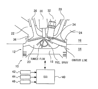
injector and the spark plug being provided in an upper part of a combustion
chamber. In
the internal combustion engine, a distance from a center position of a
discharge gap of the
spark plug to a center position of the injection hole which is closest to the
spark plug
among the plurality of injection holes is set within a specific range. In the
internal
combustion engine, a control for applying a high voltage to the spark plug is
performed
over a period from a time point after a lapse of a predetermined time from the
start of a
fuel injection to a time point when the fuel injection is completed.
CA 2970387 2019-03-15
- 2 -
[0004]
In the above-described control, a fuel injection period of the injector
overlaps with
a period of applying the high voltage to the spark plug. When the fuel is
injected by the
injector which is supplied with the fuel in a pressurized condition, a low
pressure area is
formed by entraining air around the fuel spray injected from each injection
hole
(entrainment). Therefore, when the above-described control is performed, a
discharge
spark generated in the discharge gap is attracted to the low pressure area
formed by the
fuel spray from the injection hole closest to the spark plug. The internal
combustion
engine can thereby improve ignitability of an air-fuel mixture formed around
the spark
plug.
[0005]
Patent Literature 1 further introduces activation of an exhaust gas cleaning
catalyst
as applications of the above described attraction action. Although not
mentioned in
Patent Literature 1, the exhaust gas cleaning catalyst is generally activated
by changing an
ignition period, which is normally set near a compression top dead center
(i.e., a period of
applying a high voltage to the spark plug), to a period retarded from the
compression top
dead center.
[0006]
When the above-described control of Patent Literature 1 is applied for the
general
activation of the exhaust gas cleaning catalyst, the ignition period set at a
retarded side
from the compression top dead center overlaps with a fuel injection period to
improve the
ignitability of the air-fuel mixture formed around the spark plug. However, if
an igniting
environment is changed due to some factors and therefore is out of a desired
range, a
combustion state may become unstable in spite of the above-described
attraction action.
CA 2970387 2017-06-12
- 3 -
In combustion cycles during the control for activating the exhaust gas
cleaning catalyst,
when the number of combustion cycles in which such a situation occurs is
increased, a
combustion fluctuation between cycles becomes large, and drivability is
affected.
[0007]
The present application addresses the above problems, and an aspect of the
present
application is to suppress the combustion fluctuation between cycles when the
control
performed so that the fuel injection period of the injector overlaps with the
period of
applying the high voltage to the spark plug is applied for the activation of
the exhaust gas
cleaning catalyst.
Summary
[0008]
A control device for an internal combustion engine according to the present
application is a device for controlling an internal combustion engine
comprising: an
injector, a spark plug, and an exhaust gas cleaning catalyst. The injector is
configured to
be provided in an upper part of a combustion chamber and is configured to
inject fuel from
a plurality of injection holes into a cylinder. The spark plug is configured
to ignite an
air-fuel mixture in the cylinder using a discharge spark, and is provided on a
downstream
side of the fuel injected from the plurality of injection holes and above a
contour surface
of the fuel spray pattern which is closest to the spark plug among the fuel
spray patterns
injected from the plurality of injection holes. The exhaust gas cleaning
catalyst is
configured to clean an exhaust gas from the combustion chamber.
In order to activate the exhaust gas cleaning catalyst, the control device is
configured to control the spark plug so as to generate the discharge spark in
an ignition
period retarded from a compression top dead center, and control the injector
so as to
CA 2970387 2017-06-12
- 4 -
perform first injection at a timing advanced from the compression top dead
center and
second injection at a timing retarded from the compression top dead center,
the second
injection being performed so that an injection period overlaps with at least a
part of the
ignition period.
When it is determined that a parameter related to combustion fluctuation
between
cycles exceeds a threshold, the control device for an internal combustion
engine according
to the present application is further configured to control the spark plug and
the injector so
that an interval from a start timing of the ignition period to a completion
timing of an
injection period of the second injection is increased as compared with a case
where it is
determined that the parameter is lower than the threshold.
[0009]
An air-fuel mixture containing the fuel spray by the first injection generates
initial
flame in the ignition period. When the second injection is performed so that
an injection
period overlaps with at least a part of the ignition period, at least the
initial flame is
attracted to the low pressure area formed around the fuel spray injected from
the injection
hole which is closest to the spark plug. When the second injection is
performed, the
attracted initial flame is brought into contact with the fuel spray injected
by the second
injection, and the fluctuation for growing the initial flame is to be
promoted.
However, if this contact is not sufficient, the combustion for growing the
initial
flame becomes unstable. When the number of cycles in which the combustion for
growing the initial flame becomes unstable is increased, the combustion
fluctuation
between cycles becomes large.
In this regard, when it is determined that the parameter related to the
combustion
fluctuation between cycles exceeds the threshold, the interval from the start
of the ignition
CA 2970387 2017-06-12
- 5 -
period to the completion of the second injection becomes longer by controlling
so that the
interval from the start timing of the ignition period to the completion timing
of the
injection timing of the second injection is increased as compared with the
case where it is
determined that the parameter is lower than the threshold, and the start of
the second
injection is waited for until the initial flame is grown to some extent.
Accordingly, the
situation that the attracted initial flame and discharge spark and the fuel
spray injected by
the second injection are not sufficiently contacted can be avoided.
[0010]
When the parameter exceeds the threshold, the control device may change an
increasing amount of the interval in accordance with an amount of the
deviation between
the parameter and the threshold.
[0011]
When it is determined that the parameter related to the combustion fluctuation
between cycles exceeds the threshold, the increasing amount of the interval is
changed in
accordance with the amount of the deviation between the parameter and the
threshold,
thereby permitting the reliable and sufficient contact between the attracted
initial flame
and the fuel spray injected by the second injection.
[0012]
The second injection may be completed at a timing advanced from the completion
timing of the ignition period.
[0013]
When the second injection is completed at a timing retarded from the
completion
timing of the ignition period, only the initial flame is attracted to the low
pressure area.
On the other hand, when the second injection is completed at a timing advanced
from the
CA 2970387 2017-06-12
- 6 -
completion timing of the ignition period, both of the initial flame and the
discharge spark
are attracted to the low pressure area. Both of the initial flame and
discharge spark thus
attracted are brought into contact with the fuel spray injected by the second
injection.
Therefore, when the second injection is completed at the timing advanced from
completion timing of the ignition period, the combustion for growing the
initial flame is
further promoted as compared with a case where the second injection is
completed at the
timing retarded from the completion timing of the ignition period.
[0014]
The parameter may be a variation of time required until a crankshaft is
rotated by a
predetermined angle, or a variation of a crank angle period from the start
timing of the
ignition period until a mass fraction burnt reaches a predetermined ratio.
[0015]
When the parameter related to the combustion fluctuation between cycles is the
variation of time required until the crankshaft is rotated by the
predetermined angle, or the
variation of the crank angle period from the start timing of the ignition
period until the
mass fraction burnt reaches the predetermined ratio, the combustion
fluctuation between
cycles is detected with a higher accuracy.
[0016]
A control device for an internal combustion engine according to the present
application can suppress a combustion fluctuation between cycles when a
control
performed so that a fuel injection period of an injector overlaps with a
period of applying a
high voltage to a spark plug is applied for activation of an exhaust gas
cleaning catalyst.
Brief Description of Drawings
[0017]
CA 2970387 2017-06-12
- 7 -
Fig. 1 is a diagram illustrating a system configuration according to an
embodiment
of the present application;
Fig. 2 is a diagram illustrating an outline of a catalyst warming-up control;
Fig. 3 is a diagram illustrating an expansion stroke injection;
Fig. 4 is a diagram illustrating an attraction action of a discharge spark and
initial
flame by the expansion stroke injection;
Fig. 5 is a graph showing a relationship between an interval from a start of
an
ignition period to a completion of an expansion stroke injection (interval
between the
ignition start and the injection completion) and a combustion fluctuation
rate;
Fig. 6 is a diagram illustrating an example of a base adaptive value map;
Fig. 7 is a graph showing transition of an ignition timing of a spark plug 32
(more
precisely, the start timing of the ignition period) and an engine coolant
temperature at a
cold start-up of an internal combustion engine;
Fig. 8 is a diagram illustrating an in-cylinder state when a growth speed of
an initial
flame is slow;
Fig. 9 is a diagram for illustrating the in-cylinder state when a distance
between an
outer spray pattern and an electrode part 34 is increased;
Fig. 10 is a graph showing problems when the ignition timing is advanced;
Fig. 11 is a graph showing a modification method of the interval from the
start of
the ignition period to the completion of the expansion stroke injection;
Fig. 12 is a diagram illustrating the in-cylinder state when a base adaptive
value is
modified to increase the interval from the start of the ignition period to the
completion of
the expansion stroke injection;
CA 2970387 2017-06-12
- 8 -
Fig. 13 is a graph explaining the effects when the base adaptive value is
modified
to increase the interval from the start of the ignition period to the
completion of the
expansion stroke injection;
Fig. 14 is a flowchart illustrating an example of a process performed by an
ECU 40
in the embodiment of the present application;
Fig. 15 is a graph showing an example of a Gat 30 when the internal combustion
engine is cold-started, and transition of a variation a of the Gat 30;
Fig. 16 is a graph showing the relationship between the difference between the
variation a of the Gat 30 and the criterion and the correction value for
increasing the
interval;
Fig. 17 is a graph showing the relationship between the combustion fluctuation
rate
and the variation of the SA-CA10 when the internal combustion engine is cold-
started;
and
Fig. 18 is a graph showing an example of transition of the variation a of the
SA-
CA10.
Description of Embodiments
[0018]
Hereafter, embodiments of the present application are described based on the
drawings. Note that common elements in the respective figures are denoted by
the same
signs, and the duplicated descriptions are omitted. The present application is
not limited
by the following embodiments.
[0019]
[Description of System Configuration]
CA 2970387 2017-06-12
- 9 -
Fig. 1 is a diagram illustrating a system configuration according to the
embodiment
of the present application. As illustrated in Fig. 1, a system according to
the present
embodiment comprises an internal combustion engine 10 mounted in a vehicle.
The
internal combustion engine 10 is a four-stroke one-cycle engine. The internal
combustion engine 10 has a plurality of cylinders, and one cylinder 12 is
illustrated in Fig.
1. The internal combustion engine 10 comprises a cylinder block 14 in which
the
cylinder 12 is formed, and a cylinder head 16 disposed on the cylinder block
14. A
piston 18 is disposed in the cylinder 12, the piston 18 reciprocatingly moving
in an axial
direction of the piston 18 (a vertical direction in the present embodiment). A
combustion
chamber 20 of the internal combustion engine 10 is defined by at least a wall
surface of
the cylinder block 14, a bottom surface of the cylinder head 16, and a top
surface of the
piston 18.
[0020]
Two intake ports 22 and two exhaust ports 24 which are communicated with the
combustion chamber 20 are formed in the cylinder head 16. An intake valve 26
is
provided in an opening of the intake port 22 which is communicated with the
combustion
chamber 20. An exhaust valve 28 is provided in an opening of the exhaust port
24 which
is communicated with the combustion chamber 20. An injector 30 is provided in
the
cylinder head 16 so that a tip of the injector 30 faces the combustion chamber
20 from
substantially center of an upper part of the combustion chamber 20. The
injector 30 is
connected to a fuel supply system comprising a fuel tank, a common rail, a
supply pump,
and the like. The tip of the injector 30 has a plurality of injection holes
arranged radially.
When a valve of the injector 30 is opened, fuel is injected from these
injection holes in a
high pressure state.
CA 2970387 2017-06-12
- 10 -
[0021]
In the cylinder head 16, a spark plug 32 is provided so as to be located on
the
exhaust valve 28 side of the injector 30 and in the upper part of the
combustion chamber
20. The spark plug 32 has an electrode part 34 at a tip thereof, the
electrode part 34
comprising a center electrode and a ground electrode. The electrode part 34 is
disposed
so as to protrude to an area above a contour surface of a fuel spray pattern
(hereinafter also
referred to as an "outer spray pattern") injected from the injector 30 (i.e.,
an area from the
outer spray pattern to the bottom surface of the cylinder head 16). More
particularly, the
electrode part 34 is disposed so as to protrude to the area above the contour
surface of the
fuel spray pattern which is closest to the spark plug 32 among the fuel spray
patterns
injected radially from the injection holes of the injector 30. Note that a
contour line
drawn in Fig. 1 represents the contour surface of the fuel spray pattern which
is closest to
the spark plug 32 among the fuel spray patterns injected from the injector 30.
[0022]
The intake port 22 extends substantially straight from an inlet on an intake
passage
side toward the combustion chamber 20. A flow passage cross-sectional area of
the
intake port 22 is reduced at a throat 36 which is a connection part with the
combustion
chamber 20. Such a shape of the intake port 22 generates a tumble flow in
intake air
which flows from the intake port 22 into the combustion chamber 20. The tumble
flow
swirls in the combustion chamber 20. More particularly, the tumble flow
proceeds from
the intake port 22 side to the exhaust port 24 side in the upper part of the
combustion
chamber 20, and then proceeds from the upper part of the combustion chamber 20
downward at the exhaust port 24 side. The tumble flow proceeds from the
exhaust port
24 side to the intake port 22 side in the lower part of the combustion chamber
20, and then
CA 2970387 2017-06-12
- 11 -
proceeds from the lower part of the combustion chamber 20 upward at the intake
port 22
side. A recess is formed on the top surface of the piston 18 forming the lower
part of the
combustion chamber 20 in order to conserve the tumble flow.
[0023]
As illustrated in Fig. 1, the system according to the present embodiment
comprises
an ECU (Electronic Control Unit) 40 as control means. The ECU 40 comprises a
RAM
(Random Access Memory), a ROM (Read Only Memory), a CPU (Central Processing
Unit), and the like. The ECU 40 receives signals from various sensors mounted
on the
vehicle, and processes the received signals. The various sensors comprise at
least a crank
angle sensor 42 which detects a rotation angle of a crankshaft connected to
the piston 18,
an accelerator opening sensor 44 which detects a depression amount of an
accelerator
pedal operated by a driver, and a temperature sensor 46 which detects a
temperature of
coolant in the internal combustion engine 10 (hereinafter referred to as
"engine coolant
temperature"). The ECU 40 processes the signals received from the individual
sensors to
operate various actuators according to a predetermined control program. The
actuator
operated by the ECU 40 comprises at least the injector 30 and the spark plug
32 described
above.
[0024]
[Starting Control by ECU 40]
In the present embodiment, the control for promoting the activation of an
exhaust
gas cleaning catalyst (hereinafter also referred to as ''catalyst warming-up
control") is
performed by the ECU 40 illustrated in Fig. 1 as control immediately after the
cold start-
up of the internal combustion engine 10. The exhaust gas cleaning catalyst is
a catalyst
which is provided in an exhaust passage of the internal combustion engine 10.
An
CA 2970387 2017-06-12
- 12 -
example of the exhaust gas cleaning catalyst comprises a three-way catalyst
which cleans
nitrogen oxides (N0x), hydrocarbons (HC), and carbon monoxide (CO) in the
exhaust gas
when the atmosphere of the catalyst in an activated state is near the
stoichiometry.
[0025]
The catalyst warming-up control performed by the ECU 40 is described with
reference to Figs. 2 to 7. Fig. 2 illustrates a timing of the injection by the
injector 30 and
a starting timing of an ignition period of the spark plug 32 (a starting
timing of a discharge
period of the electrode part 34) during the catalyst warming-up control. As
illustrated in
Fig. 1 during the catalyst warming-up control, the injector 30 performs first
time injection
(first injection) in an intake stroke, and then performs second time injection
(second
injection) with an amount (as an example, about 5 mm3/st) smaller than the
first time
injection in an expansion stroke after a compression top dead center. Note
that, in the
following description, the first time injection (first injection) is referred
to as "intake
stroke injection," and the second time injection (second injection) is
referred to as
"expansion stroke injection." As illustrated in Fig. 2, during the catalyst
warming-up
control, the starting timing of the ignition period of the spark plug 32 is
set to a timing
retarded from the compression top dead center. In Fig. 2, the expansion stroke
injection
is performed at a timing retarded from the starting timing of the ignition
period, but the
expansion stroke injection may be started at a timing advanced from the
starting timing of
the ignition period. In this regard, the description is provided with
reference to Fig. 3.
[0026]
Fig. 3 is a diagram illustrating a timing relationship between an injection
period
and an ignition period in the expansion stroke injection. Fig. 3 illustrates
four injections
A, B, C and D which are started at different timings, respectively. The
injections A, B, C
CA 2970387 2017-06-12
- 13 -
and D are started at different timings, respectively, but all injection
periods thereof have
the same length in the expansion stroke injection. The ignition period
illustrated in Fig. 3
is equal to the ignition period during the catalyst warming-up control
(setting period). In
the present embodiment, the injection B performed during which the ignition
period is
started, the injection C performed during the ignition period, and the
injection D
performed during which the ignition period is completed, as illustrated in
Fig. 3,
correspond to the expansion stroke injection. The injection A performed at a
timing
advanced from the start timing of the ignition period does not correspond to
the expansion
stroke injection in the present embodiment. This is because it is necessary
that at least a
part of the injection period overlaps with the ignition period in the
expansion stroke
injection in order to achieve an attraction action described later.
[0027]
[Attraction Action by Expansion Stroke Injection]
Fig. 4 is a diagram illustrating an attraction action of a discharge spark and
initial
flame in the expansion stroke injection. An upper part and a middle part (or a
lower part)
of Fig. 4 illustrate two different states of the discharge spark generated by
the electrode
part 34 during the ignition period of the spark plug 32 and the initial flame
generated by
the discharge spark from an air-fuel mixture containing the fuel spray
injected by the
intake stroke injection, respectively. The upper part of Fig. 4 illustrates a
state where the
expansion stroke injection is not performed. The middle part (or the lower
part) of Fig. 4
illustrates a state where the expansion stroke injection is performed. Note
that, for
convenience of the description, Fig. 4 illustrates only fuel spray pattern
which is closest to
the spark plug 32 among fuel spray patterns injected by the expansion stroke
injection.
[0028]
CA 2970387 2017-06-12
- 14 -
As illustrated in the upper part of Fig. 4, when the expansion stroke
injection is not
performed, the discharge spark generated by the electrode part 34 and the
initial flame
extend in a tumble flow direction. On the other hand, as illustrated in the
middle part of
Fig. 4, when the expansion stroke injection is performed, a low pressure area
is formed
around the fuel spray (entrainment), and the discharge spark generated by the
electrode
part 34 and the initial flame are attracted in a direction opposite to the
tumble flow
direction. Thus, as illustrated in the lower part of Fig. 4, the attracted
discharge spark
and initial flame are brought into contact with the fuel spray injected by the
expansion
stroke injection, are entrained in the fuel spray, and grows rapidly. The
growth of the
initial flame caused by both of the discharge spark and initial flame thus
attracted occurs
in the injections B and C in illustrated in Fig. 3. The growth of the initial
flame in the
injection D in Fig. 3 is described later.
[0029]
The fuel spray injected in the expansion stroke is affected by the tumble flow
and
the in-cylinder pressure. When the expansion stroke injection is performed at
a timing
advanced from the starting timing of the ignition period of the spark plug 32
(see the
injection A in Fig. 3), the fuel spray injected by this injection changes in
its shape before
reaching the electrode part 34. As a result, a concentration of the air-fuel
mixture around
the spark plug is unstable, and a combustion fluctuation between cycles
becomes large.
However, if the expansion stroke injection is performed so that at least a
part of the
injection period overlaps with the ignition period (see the injections B, C in
Fig. 3), the
attraction action illustrated in the middle part of Fig. 4 can be achieved.
Even if the fuel
spray injected by the expansion stroke injection changes in its shape, the
combustion for
growing the initial flame (hereinafter also referred to as "initial
combustion'') can be
CA 2970387 2017-06-12
- 15 -
stabilized, thereby suppressing the combustion fluctuation between cycles.
Furthermore,
the combustion following the initial combustion or the grown initial flame can
stabilize
the combustion further involving the air-fuel mixture containing the fuel
spray injected by
the intake stroke injection (hereinafter also referred to as "main
combustion"). In the
injection D illustrated in Fig. 3, the discharge spark disappears when the
ignition period is
completed, but the initial flame remains. The attraction action caused by the
fuel spray
injected by the expansion stroke injection allows the initial flame to be
brought into
contact with the fuel spray. Accordingly, the initial flame is stabilized
similarly to the
cases of the injections B, C illustrated in Fig. 3, thereby suppressing the
combustion
fluctuation between cycles.
[0030]
[Interval Control]
In the catalyst warming-up control, the ECU 40 controls an interval from the
start
of the ignition period of the spark plug 32 to the completion of the expansion
stroke
injection. Fig. 5 is a graph showing a relationship between the interval from
the start of
the ignition period to the completion of the expansion stroke injection
(interval between
the ignition start and the injection completion) and a combustion fluctuation
rate. The
combustion fluctuation rate in Fig. 5 is obtained by changing the start timing
of the
expansion stroke injection whose injection period (that is, injection amount)
is fixed while
fixing the start timing and completion timing of the ignition period. As shown
in Fig. 5,
a line which indicates the combustion fluctuation rate with respect to the
''interval between
the ignition start and the injection completion" is a downward convex line. In
Fig. 5,
when the start timing of the ignition period (ignition start) and the start
timing of the
expansion stroke injection (injection start) are matched, the combustion
fluctuation rate
CA 2970387 2017-06-12
- 16 -
indicates the smallest value at the retarded side from the timing of the
ignition start which
is the same as the timing of the injection start.
[0031]
The ROM of the ECU 40 stores a map of a value of the ''interval between the
ignition start and the injection completion" when the combustion fluctuation
rate indicates
the smallest value as shown in Fig. 5 (hereinafter also referred to as a "base
adaptive
value") associated with the engine operation state (hereinafter also referred
to as a "base
adaptive value map"), and the map is read out from the ROM when the catalyst
warming-
up control is performed. Fig. 6 is a diagram illustrating an example of the
base adaptive
value map. As illustrated in Fig. 6, the base adaptive value map is created as
a two-
dimensional map by defining an engine speed and an engine load kl as both
axes. Since
the base adaptive value map is created by each of the engine coolant
temperature regions
divided at intervals of a predetermined temperature, there are a plurality of
such two-
dimensional maps actually. As indicated by an arrow in Fig. 6, the base
adaptive value is
set to have a value on the retarded side as the engine speed becomes higher or
as the
engine load becomes lower. This reason is because the growth of the initial
flame is
relatively retarded when the engine speed is high, and the growth of the
initial flame is
relatively fast as the in-cylinder environment is improved when the engine
load is high.
[0032]
In the catalyst warming-up control, specifically, the start timing of the
ignition
period of the spark plug 32 and the completion timing of the expansion stroke
injection are
decided as follows. First, the start timing of the ignition period of the
spark plug 32 is
decided in accordance with a basic ignition timing and a retard correction
amount. Then,
the completion timing of the expansion stroke injection is decided by adding
the base
CA 2970387 2017-06-12
- 17 -
adaptive value obtained from the base adaptive value map and the engine
operation state
to the decided start timing of the ignition period. Fig. 7 is a graph showing
transition of
the ignition timing of the spark plug 32 (more precisely, the start timing of
the ignition
period) and the engine coolant temperature at the cold start-up of the
internal combustion
engine. When the engine is started up at a time to indicated in Fig. 7, an
operation mode
for performing the catalyst warming-up control (hereinafter also referred to
as a "catalyst
warming-up mode") is started from a time ti immediately after the time to, and
the ignition
timing is gradually set to a value on the retarded side. The catalyst warming-
up mode is
completed at a time t2 when the engine coolant temperature reaches a criterion
(as an
example, 50 C), and then the ignition timing is gradually set to the value on
the retarded
side.
[0033]
Note that the basic ignition timing is stored in the ROM of the ECU 40 as a
value
according to the engine operation conditions (mainly, the intake air amount
and the engine
speed). The retard correction amount is decided based on the map of the retard
correction amount associated with the engine coolant temperature (hereinafter
also
referred to as a "retard correction amount map"). The retard correction amount
map is
stored in the ROM of the ECU 40 similarly to the base adaptive value map, and
is read out
from the ROM when the catalyst warming-up control is performed.
[0034]
[Problems When Igniting Environment Is Out Of Desired Range]
In the system illustrated in Fig. 1, if an igniting environment is changed due
to
some factors and therefore is out of a desired range, a combustion state
easily may become
unstable in spite of the above-described attraction action caused by the
expansion stroke
CA 2970387 2017-06-12
- 18 -
injection. For example, when deposits are accumulated in the injection holes
of the
injector 30, the injection amount of the intake stroke injection is reduced.
Even when the
air amount is incorrectly read in an amount smaller than the original amount
when the
injection amount of the intake stroke injection is calculated, the injection
amount of the
intake stroke injection is reduced. When the injection amount of the intake
stroke
injection is reduced, the fuel concentration around the spark plug 32 becomes
lower and
the growth speed of the initial flame (referred to as a growth speed of the
initial flame
before contacting with the fuel spray injected by the expansion stroke
injection, the same
shall apply hereinafter) becomes slower. In a case of poor learning regarding
valve
timings of the intake valve 26 and the exhaust valve 28, a ratio of exhaust
gas remaining in
the combustion chamber 20 is increased, and the growth speed of the initial
flame
becomes slower. When the growth speed of the initial flame becomes slower, the
initial
flame may not be brought into contact with the fuel spray injected by the
expansion stroke
injection, and the combustion fluctuation between cycles becomes large.
[0035]
Fig. 8 is a diagram illustrating the in-cylinder state when the growth speed
of the
initial flame is slow. An upper part of Fig. 8 illustrates the in-cylinder
state when the
igniting environment is within the desired range, the in-cylinder state being
the same as
the in-cylinder state illustrated in the lower part of Fig. 4. In this case,
the discharge
spark and initial flame generated by the electrode part 34 are attracted to
and brought into
contact with the fuel spray injected by the expansion stroke injection, and
the initial flame
is rapidly grown as described above. That is, there is no particular problem
in the growth
speed of the initial flame in this case. On the other hand, the lower part of
Fig. 8
illustrates the in-cylinder state when the growth speed of the initial flame
is slow. In this
CA 2970387 2017-06-12
- 19 -
case, the discharge spark generated by the electrode part 34 is attracted to
the fuel spray
injected by the expansion stroke injection, but the intended attraction of the
initial flame
whose growth speed is slow may not be achieved. Therefore, the initial flame
may not
be brought into contact with the fuel spray injected by the expansion stroke
injection.
The initial combustion becomes unstable, and the main combustion following the
initial
combustion also becomes unstable.
[0036]
For example, when a projection amount of the electrode part 34 to the
combustion
chamber 20 is reduced due to replacement of the spark plug 32, and when the
spray angle
is changed due to accumulation of deposits in the injection holes of the
injector 30, the
distance between an outer spray pattern and the electrode part 34 is
increased. When the
distance between the outer spray pattern and the electrode part 34 is
increased, the initial
flame may not be brought into contact with the fuel spray injected by the
expansion stroke
injection, and the combustion fluctuation between cycles may become large.
[0037]
Fig. 9 is a diagram for illustrating the in-cylinder state when the distance
between
the outer spray pattern and the electrode part 34 is increased. An upper part
of Fig. 9
illustrates the in-cylinder state when the igniting environment is within the
desired range,
the in-cylinder state being the same as the in-cylinder states illustrated in
the lower part of
Fig. 4 and the upper part of Fig. 8. On the other hand, the lower part of Fig.
9 illustrates
the in-cylinder state when the distance between the outer spray pattern and
the electrode
part 34 is increased. In this case, since the distance between the low
pressure area and
the discharge spark and initial flame generated by the electrode part 34 is
increased, the
low pressure area being formed around the fuel spray injected by the expansion
stroke
CA 2970387 2017-06-12
- 20 -
injection, the intended attraction may not be achieved. Therefore, the initial
flame may
not be brought into contact with the fuel spray injected by the expansion
stroke injection.
Note that a contour line drawn in Fig. 9 represents the contour surface of the
fuel spray
pattern which is closest to the spark plug 32 among the fuel spray patterns
injected from
the injector 30.
[0038]
If the start timing of the ignition period is advanced, the in-cylinder
environment is
improved. When the growth speed of the initial flame is reduced (see the lower
part of
Fig. 8), the initial flame can be brought into contact with the fuel spray
injected by the
expansion stroke injection by mitigating the reduction of the growth speed.
When the
distance between the outer spray pattern and the electrode part 34 is
increased (see the
lower part of Fig. 9), the initial flame can be brought into contact with the
fuel spray
injected by the expansion stroke injection by promoting the growth speed of
the initial
flame. However, if the start timing of the ignition period is advanced, the
exhaust energy
which can be applied to the exhaust gas cleaning catalyst is reduced, and the
time is
required for the activation of the exhaust gas cleaning catalyst.
[0039]
These problems are described in detail with reference to Fig. 10. When the
igniting environment is within the desired range, the period until the initial
flame
generated from the fuel spray injected by the intake stroke injection is grown
to a size
enough to be brought into contact with the fuel spray injected by the
expansion stroke
injection can be a period within a proper range. As indicated a solid line (in
a normal
state) in a middle part of Fig. 10, even when the ignition timing (more
precisely, the start
timing of the ignition period) is set to a crank angle CAI on the retarded
side, the growth
CA 2970387 2017-06-12
-21 -
speed of the initial flame can be a value (vi) within the proper range. As
indicated in a
solid line (in the normal state) in an upper part of Fig. 10, the combustion
fluctuation rate
can be smaller than the criterion. However, when the igniting environment is
changed
and therefore is out of a desired range, the period until the initial flame
generated from the
fuel spray injected by the intake stroke injection is grown to a size enough
to be brought
into contact with the fuel spray injected by the expansion stroke injection is
increased.
As indicated by a broken line (when the combustion is deteriorated) in the
middle part of
Fig. 10, when the ignition timing is set to the crank angle CAI, the growth
speed of the
initial flame is reduced to a value (v2) which is out of the proper range.
Therefore, as
indicated by a broken line (when the combustion is deteriorated) in the upper
part of Fig.
10, the combustion fluctuation rate exceeds the criterion.
[0040]
Even when the igniting environment is out of the desired range, the tendency
of the
growth speed of the initial flame can be changed by changing the ignition
timing to the
advanced side. Specifically, if the ignition timing is reset from the crank
angle CAI to
the crank angle CA2, the growth speed of the initial flame can be returned
from the value
(v2) which is out of the proper range to the value (vi) which is within the
proper range.
Thus, the initial flame generated from the fuel spray injected by the intake
stroke injection
can be brought into contact with the fuel spray injected by the expansion
stroke injection,
thereby allowing the combustion fluctuation rate to be smaller than the
criterion.
However, as shown in a lower part of Fig. 10, when the ignition timing is
reset to the
crank angle CA2, the exhaust energy is reduced as compared with the case where
the
ignition timing is set to the crank angle CAI. Therefore, the time is required
for the
activation of the exhaust gas cleaning catalyst only by the reduction of the
exhaust energy.
CA 2970387 2017-06-12
- 22 -
[0041]
In the present embodiment, to avoid such situations, the base adaptive value
obtained from the base adaptive value map is modified when it is expected that
the initial
flame may not be brought into contact with the fuel spray injected by the
expansion stroke
injection because the igniting environment is changed. Fig. 11 is a graph
showing a
modification method of the interval from the start of the ignition period to
the completion
of the expansion stroke injection. Similarly to Fig. 5, Fig. 11 illustrates a
relationship
between the "interval between the ignition start and the injection completion'
and the
combustion fluctuation. As seen from comparing Figs. 5 and 11, the
relationship is
drawn by a solid line in Fig. 5, but is drawn by a broken line in Fig. 11.
[0042]
As explained in Figs. 8 to 10, when the initial flame may not be brought into
contact with the fuel spray injected by the expansion stroke injection, the
combustion
fluctuation rate becomes large. That is, as shown in Fig. 11, the relationship
between the
"interval between the ignition start and the injection completion" and the
combustion
fluctuation is changed from the relationship drawn by a broken line to the
relationship
drawn by a solid line. However, when the expansion stroke injection is
performed with
the combustion fluctuation rate set to the base adaptive value, the combustion
fluctuation
rate exceeds the criterion. In this regard, if the base adaptive value is
modified to
increase the "interval between the ignition start and the injection
completion" according to
the relationship indicated by the solid line after the change, the combustion
fluctuation rate
can be smaller than the criterion.
[0043]
CA 2970387 2017-06-12
- 23 -
Note that, as described above, the base adaptive value is a value of the
"interval
between the ignition start and the injection completion" when the combustion
fluctuation
rate indicates the smallest value in the case where the igniting environment
is within the
desired range. Even when the expansion stroke injection is performed based on
the
modified "interval between the ignition start and the injection completion,"
the
combustion fluctuation rate itself does not become small as compared with the
case where
the igniting environment is within the desired range. However, if the base
adaptive value
is modified to increase the "interval between the ignition start and the
injection
completion," the combustion fluctuation rate can be made to approach the
combustion
fluctuation rate in the case where the igniting environment is within the
desired range by
making the combustion fluctuation rate smaller than the criterion.
[0044]
Fig. 12 is a diagram illustrating the in-cylinder state when the base adaptive
value
is modified to increase the interval from the start of the ignition period to
the completion
of the expansion stroke injection. Both of an upper part and a lower part of
Fig. 12
illustrate the in-cylinder state when the igniting environment is out of the
desired range.
As a difference between the upper part and the lower part of Fig. 12, the
upper part
illustrates the case where the ignition timing is advanced with the "interval
between the
ignition start and the injection completion" fixed to the base adaptive value,
and the lower
part illustrates the case where the base adaptive value is modified to
increase the "interval
between the ignition start and the injection completion."
[0045]
As seen from comparing the upper part and the lower part of Fig. 12, when the
"interval between the ignition start and the injection completion" is fixed to
the base
CA 2970387 2017-06-12
- 24 -
adaptive value (see the upper part), the initial flame whose growth speed is
slow may not
be brought into contact with the fuel spray injected by the expansion stroke
injection. On
the other hand, if the base adaptive value is modified to increase the
"interval between the
ignition start and the injection completion" (see the lower part), the initial
flame can be
brought into contact with the fuel spray injected by the expansion stroke
injection at a
stage when the initial flame is grown to some extent. The state where the
initial flame
comes into contact with the fuel spray injected by the expansion stroke
injection
approaches the state where both of the initial flame and the fuel spray are
contacted when
the igniting environment is within the desired range. Therefore, the initial
combustion
can be stabilized to suppress the combustion fluctuation, and the main
combustion can be
also stabilized.
[0046]
If the base adaptive value is modified to increase the "interval between the
ignition
start and the injection completion," it is not necessary to largely advance
the ignition
timing, thereby suppressing the reduction of the exhaust energy to be applied
to the
exhaust gas cleaning catalyst. Fig. 13 is a graph explaining the effects when
the base
adaptive value is modified to increase the interval from the start of the
ignition period to
the completion of the expansion stroke injection. The "base adaptive value (in
a normal
state) in Fig. 13 represents the exhaust energy to be applied to the exhaust
gas cleaning
catalyst when the catalyst warming-up control is performed in accordance with
the base
adaptive value and the combustion fluctuation rate in the catalyst warming-up
control in
the case where the igniting environment is within the desired range. The "base
adaptive
value (when the combustion is deteriorated)" represents the exhaust energy and
the
combustion fluctuation rate when the catalyst warming-up control is performed
in
CA 2970387 2017-06-12
- 25 -
accordance with the base adaptive value in the case where the igniting
environment is out
of the desired range. As seen from comparing both base adaptive values, the
exhaust
energy corresponding to the "base adaptive value (when the combustion is
deteriorated)"
is equivalent to that corresponding to the "base adaptive value (in the normal
state)", but
the combustion fluctuation rate corresponding to the "base adaptive value
(when the
combustion is deteriorated)" is larger than the criterion.
[0047]
An "ignition advance angle (fixed interval)" in Fig. 13 represents the exhaust
energy and the combustion fluctuation rate when the catalyst warming-up
control is
performed in accordance with the base adaptive value while advancing the
ignition timing
(more precisely, the start timing of the ignition period) in the case where
the igniting
environment is out of the desired range. As seen from comparing the "ignition
advance
angle (fixed interval)" and the "base adaptive value (when the combustion is
deteriorated)",
the combustion fluctuation rate corresponding to the "ignition advance angle
(fixed
interval)" is smaller than the criterion, but the exhaust energy corresponding
to the
"ignition advance angle (fixed interval)" is reduced.
[0048]
The value of "present application" in Fig. 13 represents the exhaust energy
and the
combustion fluctuation rate when the catalyst warming-up control is performed
in
accordance with the modified base adaptive value in the case where the
igniting
environment is out of the desired range. As seen from comparing the value of
"present
application" and the other values, the combustion fluctuation rate
corresponding to the
value of "present application" can be smaller than the criterion. The exhaust
energy
corresponding to the value of "present application" can be obtained which is
lower than
CA 2970387 2017-06-12
- 26 -
that corresponding to the "base adaptive value (in the normal state)", but is
higher than
that corresponding to the value of "ignition advance angle with fixed
interval".
Therefore, the exhaust energy required for early activation of the exhaust gas
cleaning
catalyst can be secured while suppressing the combustion fluctuation rate
increase even
when the igniting environment is out of the desired range.
[0049]
[Specific Process]
Fig. 14 is a flowchart illustrating an example of a process performed by the
ECU
40 in the embodiment of the present application. Note that routines
illustrated in this
figure are repeatedly performed in each cylinder by cycle after the start-up
of the internal
combustion engine 10.
[0050]
In the routines illustrated in Fig. 14, first, it is determined whether the
engine
coolant temperature reaches the criterion, or whether a flag regarding the
completion of
the catalyst warming-up mode is set (step S100). Specifically, in step S100,
it is
determined whether the engine coolant temperature reaches the criterion (see
Fig. 7) in
accordance with a detection value of the temperature sensor 46, or whether the
completion
flag (see step S110) is set. When it is determined that the engine coolant
temperature
reaches the criterion, or when it is determined that the completion flag is
set (in a ease of
''Yes"), the process goes out of this routine.
[0051]
When it is determined in step S100 that the engine coolant temperature does
not
reach the criterion and the completion flag is not set (in a case of "No"),
the start timing of
the ignition period of the spark plug 32 and the completion timing of the
expansion stroke
CA 2970387 2017-06-12
- 27 -
injection are decided based on the engine operation state (step S102). In step
S102, first,
the engine coolant temperature is obtained in accordance with the detection
value of the
temperature sensor 46, and the retard correction amount is obtained based on
the retard
correction amount map. The start timing of the ignition period of the spark
plug 32 is
decided in accordance with the retard correction amount and the basic ignition
timing.
The base adaptive value is obtained in accordance with the engine speed
calculated in
accordance with the detection value of the crank angle sensor 42, the engine
load
calculated in accordance with the detection value of the accelerator opening
sensor 44, and
the engine coolant temperature calculated in accordance with the detection
value of the
temperature sensor 46, and the base adaptive value map. The completion timing
of the
expansion stroke injection is decided by adding the obtained base adaptive
value to the
decided start timing of the ignition period of the spark plug 32.
[0052]
Subsequently to step S102, it is determined whether the igniting environment
is
changed (step S104). In step S104, it is determined whether a variation
(standard
deviation) a of Gat 30 exceeds the criterion after the start of the catalyst
warming-up
control, for example. A rotor of the crank angle sensor 42 is provided with
teeth having
intervals of 30 . The crank angle sensor 42 is configured to transmit a signal
every time
the crankshaft rotates by 30 . The Gat 30 is calculated as a time between
signals to be
transmitted, that is, a time required to rotate the crankshaft by 30 . Fig. 15
is a graph
showing an example of the Gat 30 when the internal combustion engine is cold-
started,
and transition of the variation a of the Gat 30. In Fig. 15, the abscissa
represents an
elapsed time after the engine is started, and a time ti represents the start
timing of the
catalyst warming-up control. As shown in Fig 15, the fluctuation of the Gat 30
is small
CA 2970387 2017-06-12
- 28 -
between the time ti and the time t3. Therefore, it is determined that the
variation a of the
Gat 30 is smaller than the criterion. When it is determined that the variation
a of the Gat
30 is smaller than the criterion (in a case of "No"), the process proceeds to
step S108.
[0053]
On the other hand, as shown in Fig. 15, the fluctuation of the Gat 30 becomes
large
between the time t3 and the time t4. Therefore, it is determined that the
variation a of the
Gat 30 is larger than the criterion. When it is determined that the variation
a of the Gat
30 exceeds the criterion (in a case of "Yes"), it can be determined that there
are the
possibilities that the igniting environment is changed due to some factors and
therefore is
out of the desired range, and the initial flame may not come into contact with
the
combustion spray injected by the expansion stroke injection. Therefore, the
start timing
of the ignition period of the spark plug 32 and the completion timing of the
expansion
stroke injection are modified (step S106). In step S106, first, the retard
correction
amount is obtained in accordance with the engine coolant temperature and the
retard
correction amount map. The start timing of the ignition period of the spark
plug 32 is
decided in accordance with the retard correction amount and the basic ignition
timing.
The base adaptive value is obtained in accordance with the engine speed, the
engine load
and the engine coolant temperature, and the base adaptive value map. The
process so far
is the same as the process in step S102. In step S106, the obtained base
adaptive value is
added to the decided start timing of the ignition period of the spark plug 32.
Furthermore,
the correction value (fixed value) for increasing the interval is further
added thereto. The
completion timing of the expansion stroke injection is decided.
[0054]
CA 2970387 2017-06-12
- 29 -
Subsequently to step S106, in step S108 it is determined whether the exhaust
gas
temperature exceeds the criterion Ti. In this step, it is determined whether
the exhaust
gas temperature exceeds the criterion T1 in accordance with the detection
value of the
temperature sensor provided on the downstream side of the exhaust gas cleaning
catalyst,
for example. If it is determined that the engine coolant temperature reaches
the criterion
(in a case of "Yes''), the completion flag is set (step S110).
[0055]
According to the routines illustrated in Fig. 14, it can be determined whether
the
igniting environment is changed in accordance with the variation a of the Gat
30 after the
catalyst warming-up control is started. When, as a result of the
determination, it is
determined that there is the possibility that the igniting environment is
changed due to
some factors and therefore is out of the desired range, the interval from the
start of the
ignition period to the completion of the expansion stroke injection can be
increased.
Even when the igniting environment is out of the desired range, the combustion
fluctuation between cycles can be suppressed.
[0056]
[Modification of Embodiment]
In the embodiment, the tumble flow formed in the combustion chamber 20 swirls
from the upper part of the combustion chamber 20 downward at the exhaust port
24 side
and from the lower part of the combustion chamber 20 upward at the intake port
22 side.
However, the tumble flow may swirl in a direction opposite to this flow
direction, that is,
the tumble flow may swirl from the upper part of the combustion chamber 20
downward at
the intake port 22 side and from the lower part of the combustion chamber 20
upward at
the exhaust port 24 side. In this case, it is necessary to change a location
of the spark
CA 2970387 2017-06-12
- 30 -
plug 32 from the exhaust valve 28 side to the intake valve 26 side. By thus
changing the
location of the spark plug 32, the spark plug 32 is located on the downstream
side of the
injector 30 in the tumble flow direction, thereby achieving the attraction
action by the
expansion stroke injection.
Furthermore, the tumble flow may not be formed in the combustion chamber 20,
because the above-described combustion fluctuation between cycles occurs
regardless of
the presence of the tumble flow formation.
[0057]
In the embodiment, the first time injection (first injection) by the injector
30 is
performed in the intake stroke, and the second time injection (second
injection) is
performed in the expansion stroke at the timing retarded from the compression
top dead
center. However, the first time injection (first injection) may be also
performed in the
compression stroke. In addition, the first time injection (first injection)
may be dividedly
performed in a plurality of times, or a divided part of the first time
injection may be also
performed in the intake stroke and the remainder may be also performed in the
compression stroke. Thus, the injection timing and the number of injections in
the first
time injection (first injection) may be modified in various ways.
[0058]
In the above-described embodiment, in the process in step S106 of Fig. 14, the
correction value for increasing the interval is defined as a fixed value.
However, the
correction value for increasing the interval may not be the fixed value. For
example, the
correction value for increasing the interval may be set to be increased as a
difference
between the variation a of the Gat 30 and the criterion shown in Fig. 15
becomes large.
When such a setting is performed, a map indicating the relationship between
the difference
CA 2970387 2017-06-12
- 31 -
between the variation a of the Gat 30 and the criterion and the correction
value for
increasing the interval (see Fig. 16) is stored in the ROM of the ECU 40, and
may be read
out from the ROM of the ECU 40 in the process of step S106.
[0059]
In the above-described embodiment, in the process in step S104 of Fig. 14, the
determination whether the igniting environment is changed is performed using
the
variation a of the Gat 30 after the start of the catalyst warming-up control.
Instead of
this variation a, the variation a of the crank angle period (hereinafter also
referred to as an
"SA-CA10") from the start timing of the ignition period until the mass
fraction burnt
(MFB) reaches 10% may be used to perform the determination. The MFB is
calculated
based on an analysis result of the in-cylinder pressure data obtained using an
in-cylinder
pressure sensor (not illustrated) provided separately in the combustion
chamber 20 and the
crank angle sensor 42, and the SA-CA10 is calculated based on the calculated
MFB.
Note that a method of calculating the MFB from the analysis result of the in-
cylinder
pressure data and a method of calculating the SA-CA10 are described in detail
in JP 2015-
094339 A and JP 2015-098799 A, and the descriptions thereof are omitted.
[0060]
Fig. 17 is a graph showing the relationship between the combustion fluctuation
rate
and the variation a of the SA-CA10. Fig. 18 is a graph showing an example of
transition
of the variation a of the SA-CA 10 when the internal combustion engine is cold-
started.
As shown in Fig. 17, the combustion fluctuation rate becomes large as the
variation a of
the SA-CA10 becomes large. That is, the variation a of the SA-CA10 is
correlated with
the combustion fluctuation rate. For example, it is determined that the
variation a of the
SA-CA10 exceeds the criterion between the time t5 and the time t6 as shown in
Fig. 18
CA 2970387 2017-06-12
- 32 -
after the start of the catalyst warming-up control, the process after step
S106 of Fig. 14
may be performed by determining that there are the possibilities that the
igniting
environment is changed due to some factors and therefore is out of the desired
range, and
the initial flame may not come into contact with the combustion spray injected
by the
expansion stroke injection variation.
In addition, not only the Gat 30 and SA-CA10, but also the time required to
rotate
the crankshaft by 600 in the ignition period (Gat60), the crank angle period
from the start
timing of the ignition period until the MFB reaches 5% (SA-CAS), and the crank
angle
period from the start timing of the ignition period until the MFB reaches 15%
(SA-CA15)
may be used. Thus, the parameters which can determine the state where the
initial flame
comes into contact with the fuel spray injected by the expansion stroke
injection
(parameters relating to the combustion fluctuation between cycles) can be used
as indexes
of the determination whether the igniting environment is changed in the above
embodiment.
CA 2970387 2017-06-12