Note: Descriptions are shown in the official language in which they were submitted.
WO 2011/073772 PCT/1B2010/003249
- 1 -
DIRECT CURRENT ARC FAULT CIRCUIT INTERRUPTER, DIRECT
CURRENT ARC FAULT DETECTOR, NOISE BLANKING CIRCUIT FOR A
DIRECT CURRENT ARC FAULT CIRCUIT INTERRUPTER, AND
METHOD OF DETECTING ARC FAULTS
BACKGROUND
Field
The disclosed concept pertains generally to arc fault detection and,
more particularly, to direct current arc fault circuit interrupters. The
disclosed
concept also pertains to direct current arc fault detectors, noise blanking
circuits for
direct current arc fault circuit interrupters, and methods of detecting arc
faults.
Background Information
It is believed that there is no known mechanism in photovoltaic (PV)
(e.g., photovoltaic; solar electric) systems to detect arcing faults and stop
strings or
string arrays from generating energy under an in-circuit (series) fault or a
short circuit
fault (e.g., without limitation, a parallel arc), which can result in a fire.
For example,
fuses at the load end of a string do not prevent this fault. For example, arcs
consume
energy that does not transfer to an inverter or load.
Known practice places a protective device (i.e., a fuse) at the load end
of a string, in one feed conductor (e.g., wire; typically the positive wire)
to open when
back feed currents exceed 150% of the fuse rating during back feed conditions
and
back feed shorts. Depending on the manufacturer, either the positive or
negative feed
wire will contain a protective device (i.e., a fuse). Depending on the local
building
codes, the system may have a grounded conductor or may be un-grounded. Some
known combiner boxes include fuses on both conductors for ungrounded systems
at
the feed end but not at the remote end. It is believed that protective devices
are not
used at the PV generating modules, at the remote end of a string, or in the
return
conductor. It is believed that all of the connecting feed conductors between
the PV
generating modules and the return conductors are un-protected from arcing
events or
short circuits of many kinds.
Figure 1 shows several parallel strings 2,4,6 of series-connected direct
current (DC) electrical generating modules 8 (e.g., PV generating modules)
with a
protective device 10 located in the positive conductor 12 of each string. This
CA 2970448 2017-06-13
WO 2011/073772 PCT/1B2010/003249
- 2 -
protective device 10 is a fuse and only protects against a reverse over
current when
the corresponding string 2,4,6 shorts and is back fed by the other PV strings
which are
bussed together at the main DC bus 14 in the combiner box 16.
It is known to employ fuses for over current protection and diodes to
block reverse current. It is believed that known strings and arrays of DC
electrical
generating modules do not provide series or parallel arc fault protection.
It is believed that fuses are essentially useless in PV power systems
since such fuses are sized at 125% and typically must open at 150% of full
load
current, while the maximum short circuit current for PV arrays does not exceed
100%
of full load current. In PV power systems, fuses protect conductors, such as
wires,
from over currents. Over currents can only result from a back feed condition.
Forward feed currents for silicon PV modules are typically limited to about
7.5 A by
the structure of the PV modules, which cannot produce more than about 7.5 A
even
when short circuited. Therefore, string fuses are useless for providing
protection from
a forward feed fault, or bus faults that occur above the string fuses.
It is believed that fuses also cannot provide protection from an arcing
fault. A fuse is typically used on each string, which is a series connected
number of
PV modules to achieve, for example, a 600 VDC potential. The string is
terminated
iri a central junction box commonly referred to as a combiner box.
Module DC/DC converters can turn off power to exposed connectors,
but are believed to lack a detection mechanism for faults. Otherwise, there is
no
protection or control at the PV module and, therefore, no way to turn off the
potential
generated by the PV modules other than to block the light and prevent
illumination of
the silicon diodes of the PV module by covering the PV modules, an impractical
strategy in the field.
DC/DC converters can help prevent backfed faults as they maintain
voltage consistency between the voltage provided by the string and the voltage
required by the DC bus to reach the maximum power point (MPP). However, there
is
no protection for series arcing faults or many short circuits between the
positive and
negative feed wires or ground.
There is room for improvement in direct current arc fault circuit
interrupters.
CA 2970448 2017-06-13
=
W02011/073772 PCT/1B2010/003249
-3 -
There is also room for improvement in direct current arc fault
detectors.
There is further room for improvement in methods of detecting arc
faults.
SUMMARY
These needs and others are met by embodiments of the disclosed
concept, which detect arcing in direct current (DC) circuits.
In accordance with one aspect of the disclosed concept, a direct current
arc fault circuit interrupter comprises: separable contacts; an operating
mechanism
structured to open and close the separable contacts; a trip circuit
cooperating with the
operating mechanism to trip open the separable contacts, the trip circuit
comprising: a
number of alternating current sensors structured to sense a current flowing
through the
separable contacts, a number of filter circuits cooperating with the number of
alternating current sensors to output a number of alternating current signals,
a number
of peak detectors cooperating with the number of filter circuits to output a
number of
peak current signals, and a processor cooperating with at least the number of
peak
detectors and the operating mechanism, the processor being structured to (a)
input the
number of peak current signals as a plurality of peak current signals or (b)
input the
number of peak current signals and determine the plurality of peak current
signals, the
processor also being structured to determine if the plurality of peak current
signals
exceed corresponding predetermined thresholds for a predetermined time, and
responsively cause the operating mechanism to trip open the separable
contacts.
The trip circuit may further comprise a direct current sensor structured
to sense the current flowing through the separable contacts; and the processor
may be
further structured to detect a level shift in the sensed current employing the
direct
current sensor.
As another aspect of the disclosed concept, a noise blanking circuit is
for a direct current arc fault circuit interrupter comprising separable
contacts and a
number of alternating current channels operatively associated with a plurality
of
alternating current signals for the separable contacts. The noise blanking
circuit
comprises: a direct current sensor structured to be in series with the
separable contacts
of the direct current arc fault circuit interrupter; and a processor
cooperating with the
CA 2970448 2017-06-13
WO 2011/073772 PCT/1B2010/003249
- 4 -
direct current sensor, the processor being structured to input a sensed direct
current
signal from the direct current sensor, and disable the number of alternating
current
channels if a rate of change of the sensed direct current signal is greater
than a first
predetermined threshold or enable the number of alternating current channels
if the
rate of change is less than a different second predetermined threshold, which
is less
than the first predetermined threshold.
As another aspect of the disclosed concept, a method of detecting arc
faults of a direct current string comprises: sensing an alternating current
flowing
through the direct current string; filtering the sensed alternating current
with a number
of filter circuits and outputting a number of alternating current signals;
determining a
plurality of peak current signals from the number of alternating current
signals; and
determining if the plurality of peak current signals exceed corresponding
predetermined thresholds for a predetermined time, and responsively tripping
the
direct current string.
As another aspect of the disclosed concept, a method detects arc faults
of an array comprising a plurality of direct current strings electrically
connected in
parallel to form the array. The method comprises: sensing an alternating
current
flowing through the array; filtering the sensed alternating current with a
number of
filter circuits and outputting a number of alternating current signals;
determining a
plurality of peak current signals from the number of alternating current
signals; and
determining if the plurality of peal( current signals exceed corresponding
predetermined thresholds for a predetermined time, and responsively tripping
the
array.
As another aspect of the disclosed concept, a direct current arc fault
detector comprises: a number of alternating current sensors structured to
sense a
current flowing through a conductor; a number of filter circuits cooperating
with the
number of alternating current sensors to output a number of alternating
current
signals; a number of peak detectors cooperating with the number of filter
circuits to
output a number of peak current signals; an output; and a processor
cooperating with
at least the number of peak detectors and the output, the processor being
structured to
(a) input the number of peak current signals as a plurality of peak current
signals or
(b) input the number of peak current signals and determine the plurality of
peak
CA 2970448 2017-06-13
WO 2011/073772
PCT/1B2010/003249
- 5 -
current signals, the processor also being structured to determine if the
plurality of
peak current signals exceed corresponding predetermined thresholds for a
predetermined time, and responsively activate the output.
As another aspect of the disclosed concept, a direct current arc fault
circuit interrupter comprises: separable contacts; an operating mechanism
structured
to open and close the separable contacts; a trip circuit cooperating with the
operating
mechanism to trip open the separable contacts, the trip circuit comprising: an
alternating current sensor structured to sense a current flowing through the
separable
contacts, a broadband filter circuit cooperating with the alternating current
sensor to
output an alternating current signal, a peak detector cooperating with the
broadband
filter circuit to output a peak current signal, and a processor cooperating
with at least
the peak detector and the operating mechanism, the processor being structured
to
input and integrate the peak current signal and to determine if the integrated
peak
current signal exceeds a predetermined threshold for a predetermined time, and
responsively cause the operating mechanism to trip open the separable
contacts.
BRIEF DESCRIPTION OF THE DRAWINGS
A full understanding of the disclosed concept can be gained from the
following description of the preferred embodiments when read in conjunction
with the
accompanying drawings in which:
Figure 1 is a block diagram in schematic form of a plurality of strings
of direct current (DC) electrical generating modules with a single protective
device
for each string located in the positive conductor.
Figure 2 is a block diagram of a photovoltaic (PV) power system
including a plurality of DC arc fault circuit interrupters in accordance with
embodiments of the disclosed concept.
Figure 3 is a plot of arc voltage and arc current for a DC arc fault.
Figure 4 is a frequency plot showing a fast Fourier transform (FFT) of
both an arcing condition and a non-arcing condition showing a significant
difference
in signal strength of the frequencies for these two conditions.
Figure 5 is a block diagram in schematic form of a DC arc fault circuit
interrupter in accordance with other embodiments of the disclosed concept.
CA 2970448 2017-06-13
W02011/073772 PCT/1B2010/003249
- 6 -
Figures 6A and 6B are flowcharts of routines providing DC arc fault
detection, control and protection, and noise blanking, respectively, for the
processor
of Figure 5.
Figure 7 is a block diagram in schematic form of a DC arc fault circuit
interrupter including three current transformers (CTS) employing three
predetermined
relatively narrow frequency bands to avoid known noise sources in accordance
with
another embodiment of the disclosed concept.
Figure 8 is a block diagram in schematic form of a DC arc fault circuit
interrupter including a single CT with three windings in accordance with
another
embodiment of the disclosed concept.
Figure 9 is a block diagram in schematic form of a DC arc fault circuit
interrupter including a shunt transformer current sensor with three active
bandpass
filters in accordance with another embodiment of the disclosed concept.
Figure 10 is a block diagram in schematic form of a DC arc fault
circuit interrupter including a broadband circuit in accordance with another
embodiment of the disclosed concept.
Figure 11 is a block diagram in schematic form of a DC arc fault
circuit interrupter including a frequency sweep circuit in accordance with
another
embodiment of the disclosed concept.
Figure 12 is a plot of a direct current signal, three alternating current
signals at different frequencies, and a trip signal before, during and after
an arc.
Figure 13 is a block diagram in schematic form of a DC arc fault
circuit interrupter including a digital signal processor in accordance with
another
embodiment of the disclosed concept.
DESCRIPTION OF THE PREFERRED EMBODIMENTS
As employed herein, the term "number" shall mean one or an integer
greater than one (i.e., a plurality).
As employed herein, the term "processor" means a preprogranuned,
programmable or dedicated logic analog (e.g., without limitation, a number of
amplifiers, filters, capacitors and/or analog timing elements) and/or digital
device that
can store, retrieve, and process data; a computer; a workstation; a personal
computer;
a microprocessor; a microcontroller; a microcomputer; a central processing
unit; a
CA 2970448 2017-06-13
WO 2011/073772
PCT/1B2010/003249
- 7 -
mainframe computer; a mini-computer; a server; a networked processor; or any
suitable processing device or apparatus.
As employed herein, the term "short circuit" means a bolted fault or an
arcing fault to the opposite polarity or to ground.
As employed herein, the term "bolted fault" means a solid or direct or
suitably low impedance electrical connection to the opposite polarity or to
ground,
typically resulting in an increase in current flow.
As employed herein, the term "arcing fault to the opposite polarity"
means an electrical connection to the opposite polarity through a conductive
plasma.
For example and without limitation, such arcing faults can include: (1) a
metal vapor
arc (or spark); (2) a plasma arc that requires a relatively hot ionized
conduction path;
and (3) arcing over a surface which has suffered from a deterioration of its
insulating
capability by way of an electrolyte contamination or carbon tracking.
As employed herein, the term "in-circuit arcing fault" or "in-circuit
arc" means a sustained arcing break (e.g., a plasma) in series electrical
connection(s),
internal to a generating module, between plural generating modules, or in
electrical
circuits running to or from a combiner box or any other electrical
junction(s),
terminal(s) or connection(s). Here, series means that there is another circuit
element
(e.g., without limitation, an inverter) present that prevents the arc from
being directly
electrically connected from the power line to the return.
As employed herein, the term "open circuit" means a break without
arcing in a series circuit electrical connection of a string.
As employed herein, the terms "arc fault circuit interrupter", "AFCI"
and "arc fault protector" mean an arc fault detector and a number of separable
contacts responsive to the arc fault detector.
As employed herein, the term "string" means a series electrical circuit
connection of a plurality of electrical generating modules.
As employed herein, the term "string protector" means a protection
device for a string and/or an electrical generating module of a string. The
string
protector includes a number of AFCI, over current and/or reverse current
protection
functions.
CA 2970448 2017-06-13
WO 2011/073772 PCT/1132010/003249
- 8 -
As employed herein, the term "combiner box" means a box, an
enclosure or another suitable structure where one end of a plurality of
strings are
fused and/or protected. A combiner box electrically combines in parallel DC
currents
from several strings.
As employed herein, the term "direct current electrical generating
module" means a photovoltaic electrical generating module, a battery or a fuel
cell.
As employed herein, the term "power line" generally refers to a power
conductor at the feed end of a string, which electrically connects electrical
generating
modules in series.
As employed herein, the term "return line" generally refers to a power
conductor extending from the remote end to the feed end of a string with no
electrical
generating modules in series.
A photovoltaic string of generating modules is an example of a series
circuit electrical connection of a plurality of electrical generating modules.
An "in-
circuit arc" can occur, for example, when an electrical circuit, comprised of
a series
circuit electrical connection of a plurality of generating modules, is opened
under load
creating an arc across a gap that sustains the arc.
A "short circuit arc" can occur, for example, when an alternative (e.g.,
a change from the "normal" conduction path (e.g., from the return conductor at
the
inverter, through all the generating modules, to the feed conductor, and back
to the
inverter)) short circuit path to the opposite polarity or ground is
established.
A short circuit can, for example and without limitation, form an
alternative and un-wanted electrical path that a conventional protection
function
cannot detect or protect for currents taking an alternative path, such that
excessive
currents can cause overheating and arcs can cause fires.
An alternative short circuit path (e.g., such as the above un-wanted
electrical path) can result in over currents due to back feed currents from
adjacent
strings to the short circuit path.
A short circuit path can be established at any point along series-
connected electrical generating modules.
A short circuit path can also be established between the return or
power line conductors from several strings routed in a common location or
raceway,
CA 2970448 2017-06-13
W02011/073772 PCT/IB2010/003249
- 9 -
to a grounded frame, conduit, or conductor, or between the return or power
line
conductors from a combiner box to an inverter.
The disclosed concept is described in association with arc fault
protection for photovoltaic (PV) circuits, although the disclosed concept is
applicable
to a wide range of DC applications, including, for example and without
limitation,
relatively higher DC voltage circuits, such as wind power, hybrid vehicles,
electric
vehicles, marine systems and aircraft.
The disclosed concept is described in association with strings including
a plurality of photovoltaic electrical generating modules, although the
disclosed
concept is applicable to strings and string arrays including a plurality of
direct current
electrical generating modules (DC EGMs).
The disclosed concept detects arcing in a DC power system by
monitoring various frequencies in the DC power feed. Typically, a base line of
electrical noise exists in the DC power feed (e.g., DC line; DC return).
Therefore,
monitoring multiple (e.g., two or more; preferably three to ensure that an arc
is
present without nuisance tripping; any suitable plural count) frequencies is
employed
to ensure correct arc detection and trip declaration and to minimize nuisance
trips.
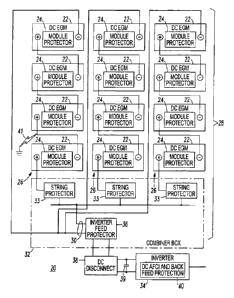
Referring to Figure 2, a photovoltaic (PV) power system 20 is shown
including a plurality of direct current (DC) arc fault circuit interrupters
(AFCIs), as
will be described. The PV power system 20 includes a plurality of DC
electrical
generating modules (EGMs), such as the example PV modules 22, each of which
includes a DC AFCI, such as the example module protector 24. Each of a
plurality of
strings 26 is formed by a plurality of the PV modules 22, which are
electrically
connected in series. An array 28 including a DC bus 30 is formed by the DC
strings
26 as are electrically connected in parallel in the combiner box 32 including
a string
protector 33 for each of the DC strings 26. The DC bus 30 of the array 28 is
electrically connected to an inverter 34 by an inverter feed protector 36 and
a DC
disconnect 38. One or both of the inverter feed protector 36 and the DC
disconnect
38 can include a DC AFCI. The inverter 34 includes a DC AFCI 40, which
provides
back feed protection.
CA 2970448 2017-06-13
W02011/073772 PCT/IB2010/003249
- 10 -
Figure 3 shows a plot of arc voltage 42 and arc current 44 versus time
46 for a DC arc fault, which occurs in time toward the left side (with respect
to Figure
3) of the plot.
Figure 4 shows a frequency plot 48 of a fast Fourier transform (FFT)
of both an arcing condition at arcing FFT 50 and a non-arcing condition at non-
arcing
FFT 52. The frequency plot 48 shows a significant difference (e.g., without
limitation, about 30 dB or more) in signal strength of the frequencies for
these two
arcing and non-arcing conditions. No inverter was present during this test.
Referring to Figure 5, a direct current (DC) arc fault circuit interrupter
(AFCI) 60 includes separable contacts 62, an operating mechanism 64 structured
to
open and close the separable contacts 62, and a trip circuit 66 cooperating
with the
operating mechanism 64 to trip open the separable contacts 62.
As will be discussed, below, in connection with Figures 7-11, the trip
circuit 66 includes a number of alternating current sensors, such as 102,
structured to
sense a current 67 flowing through the separable contacts 62, a number of
filter
circuits 68 cooperating with the number of alternating current sensors 102 to
output a
number of alternating current signals, a number of peak detectors 70
cooperating with
the number of filter circuits 68 to output a number of peak current signals
266, and a
processor 72 cooperating with at least the number of peak detectors 70 and the
operating mechanism 64. The processor 72 is structured to: (a) input the
number of
peak current signals 266 as a plurality of peak current signals or (b) input
the number
of peak current signals 266 and determine the plurality of peak current
signals 318
(Figure 11). The processor 72 is also structured to determine if the plurality
of peak
current signals exceed corresponding predetermined thresholds 74 (as shown,
for
example, with respect to line 74 of Figure 4), and responsively cause the
operating
mechanism 64 to trip open the separable contacts 62.
The processor 72 can provide the corresponding predetermined
thresholds 74 for arc detection. For example, as shown in Figure 4, the
thresholds 74
can be set above the typical total noise at the non-arcing FFT 52 and below
the typical
arc signal at the arcing FFT 50.
As shown in Figure 7, for example, the trip circuit 66 provides an arc
fault detector including a number of alternating current sensors (e.g.,
without
CA 2970448 2017-06-13
WO 2011/073772 PCT/1B2010/003249
- 11 -
limitation, three example inductive coils Li, L2, L3 are shown) structured to
sense a
current (e.g., typically, a direct current, which may have a number of
alternating
current components) flowing through a conductor 63 (e.g., in series with
separable
contacts 62), a number of filter circuits 68 cooperating with the number of
alternating
current sensors to output a number of alternating current signals, a number of
peak
detectors 70 cooperating with the number of filter circuits 68 to output a
number of
peak current signals 266 (e.g., without limitation, three are shown), an
output 73 (e.g.,
without limitation, including a signal indicating an arc fault indication; a
trip signal to
an inverter (e.g., to shutoff), a direct current disconnect, a circuit
interrupter, a switch,
and the separable contacts 62 through coil 76), and the processor 72
cooperating with
at least the number of peak detectors 70 and the output 73. The processor 72
is
structured to (a) input the number of peak current signals 266 as a plurality
of peak
current signals or (b) input the number of peak current signals 266 and
determine the
plurality of peak current signals. The processor 72 is also structured to
determine if
the plurality of peak current signals 266 exceed the corresponding
predetermined
thresholds 74 for a predetermined time, and responsively activate the output
73.
Example 1
Referring again to Figure 5, the example DC AFCI 60 can be for a
string (e.g., without limitation, DC string 26 of Figure 2 having a string
voltage of
about 24 VDC to about 600 VDC at greater than about 7 A maximum) or a DC EGM,
such as the PV module 22 of Figure 2. The DC AFCI 60 includes the current
sensor
102, an analog front end 104 and the processor 72 (e.g., without limitation,
microprocessor) that monitors the sensed string current 108 and reports the
same (e.g.,
without limitation, through communication port 110). The DC AFCI 60 can
monitor
current (I) and voltage (V). The processor 72 can include a number (e.g., one,
some
or all) of an over current protector routine 112, an arc fault protector
routine 114 (e.g.,
series; parallel) and a reverse current protector routine 116, which can
provide various
protection/alarm functions, as well as string performance (e.g., open; low
output).
The example DC AFCI 60 also includes the separable contacts 62 controlled by
the
processor 72. The DC AFCI 60 can isolate, for example, the DC EGM 22 from the
string 26 of Figure 2 responsive to at least one of the over current
protector, the arc
fault protector and the reverse current protector routines 112,114,116. The DC
AFCI
CA 2970448 2017-06-13
W02011/073772 PCT/1B2010/003249
-12-
60 can be structured to measure current through the current sensor 102 and
voltage
generated by the DC EGM 22 through divider 118. Using the current sensor 102,
the
DC AFCI 60 can sense reverse flowing (back feed) currents under any short
circuit
condition. The ability to sense back feed currents permits such DC AFCI 60 to
be
commanded to terminate the flow of such back feed currents. Back feed currents
are
unwanted, since they can over heat a DC EGM and reduce the net current
delivered to
the inverter 34 (Figure 2) or its load (not shown). Back feed currents can be
greater
than the forward feed currents if no fuse or other protection is present.
Opening the
separable contacts 62 mitigates against and/or prevents hazardous and/or
unwanted
currents if no fuse or other protection is present. Opening the separable
contacts 62
mitigates against and/or prevents hazardous and/or unwanted currents (e.g.,
reducing
energy delivered from the array 28 (Figure 2) to the load) from flowing.
Preferably, the number of local status indicators 120 and/or the
communication port 110 are also provided for remote monitoring and alarms. The
DC AFCI 60 can be structured to report a fault state or health of a
corresponding one
of the strings 26 (Figure 2) to a remote location, such as 122 (shown in
phantom line
drawing).
The DC AFCI 60 includes a power supply 124 that can receive power
from an external power supply (not shown) (switch 126 at positions "A" and
"D"),
from a main bus (not shown) (switch 126 at positions "A" and "D") and/or from
a
corresponding local DC EGM 22 (switch 126 at positions "B" and "C").
Example 2
Figure 6A shows a routine 150 providing DC arc fault detection,
control and protection for the processor 72 of Figure 5. The routine 150
enables the
processor 72 to detect a series arc fault or a parallel arc fault, such as a
parallel arc to
ground or to the return conductor. In Figure 6A, the AC (frequency) thresholds
of
step 156 (thresholds 74 of Figure 4) are valid for both series and parallel
arcs.
The routine 150 starts at 152 after which the processor 72 is initialized
at 153 and an integer, i, is set equal to zero. Next, at 154, a suitable delay
(e.g.,
without limitation, 3 mS; any suitable delay time) is introduced. Then, at
155, the
signal level is measured or input in all AC (high frequency) ranges of
interest. Next,
at 156, it is determined if a plurality (e.g., without limitation, three; any
suitable plural
CA 2970448 2017-06-13
W02011/073772 PCT/1B2010/003249
- 13 -
count) of the peak current signals (e.g., 266 of Figure 7) exceed the
corresponding
predetermined thresholds 74. If not, then at 158, the integer, i, is
decremented if it is
currently greater than zero, after which step 154 is repeated. Steps 160 and
162
determine whether the peak current signals exceed the corresponding
predetermined
thresholds 74 for a predetermined time. At 160, the integer, i, is incremented
and, at
162, it is determined if the integer, i, is equal to a predetermined value
(e.g., without
limitation, n = 10; any suitable plural count). If not, then step 154 is
repeated.
Otherwise, an arc fault is detected at 164, which causes the separable
contacts 62 to
open and causes an arc fault indicator (e.g., 120 of Figure 5) to indicate the
arc fault
condition. Finally, step 166 waits for a reset command, which resets the DC
AFCI 60
to its initial state.
For example, in Figure 7 the processor 72 is structured to determine if
all three example peak current signals 266 exceed three corresponding
predetermined
thresholds 74 for a predetermined time, and responsively cause the operating
mechanism 64 to trip open the separable contacts 62. For example, this
minimizes
nuisance trips when responsively tripping a DC string, such as 26 (Figure 2).
An optional noise blanking routine 200 of Figure 6B is a separate
routine that runs parallel to the arc fault detection routine 150 of Figure
6A. The
noise blanking routine 200 reduces nuisance trips by blocking noise from
entering the
number of filter circuits 68 and the number of peak detectors 70 when a
transient
condition occurs including a significant change in DC current level.
As is shown, for example, in Figures 7-11, the trip circuit 66 can
further include a direct current sensor 202 in series with the separable
contacts 62.
The processor 72 is further structured to cooperate with the direct current
sensor 202,
input a sensed direct current signal 204 from the direct current sensor 202,
and disable
the number of filter circuits 68 if a rate of change of the sensed direct
current signal
204 is greater than a first predetermined threshold or enable the number of
filter
circuits 68 if the rate of change is less than a different second
predetermined
threshold, which is less than the first predetermined threshold.
In the noise blanking routine 200 of Figure 6B, step 206 inputs the
sensed direct current signal 204 and accumulates an average thereof. Next, at
208, it
is determined if the number of AC channels formed by the number of filter
circuits 68
CA 2970448 2017-06-13
WO 2011/073772 PCT/1B2010/003249
- 14 -
are on. If so, then at 210, it is determined if the present sensed direct
current signal
204 is less than, for example and without limitation, half of the average of
step 206.
If so, then the number of AC channels are turned off at 212. Otherwise, or
after 212,
the routine 200 returns at 214 and is run again at 206 after a suitable delay.
On the other hand, if the number of AC channels are not on, as
determined at 208, then at 216, it is determined if the present sensed direct
current
signal 204 is, for example and without limitation, greater than 0.9 times the
average of
step 206. If not, then the routine 200 returns at 214. Otherwise, at 218, a
suitable
delay (e.g., without limitation, 50 liS; any suitable time) is provided, after
which the
number of AC channels are turned on at 220 before the routine 200 returns at
214.
This delay of step 218 is for the case when the AC channels are turned off and
should
not detect a transient condition. This provides noise blanking for at least
the period of
the delay.
The example noise blanking routine 200 is provided for transients
other than series arcs or parallel arcs or other than current changes due to
changes in
illumination. The noise blanking routine 200 can detect, for example,
relatively very
large DC steps. A relatively large (and fast or high di/dt) step will create
high
frequencies and saturate all of the high frequency AC channels. For example,
if an
inverter turns off input currents for a few microseconds, then the DC AFCI 60
(Figure
5) would see all the frequencies during this transient. Hence, it is
advantageous to
turn off the high frequency AC channels when detecting a relatively fast
transition
that went all the way (or close to) zero amperes, and then turn the high
frequency AC
channels back on when there are normal currents.
The example noise blanking routine 200 can be interrupt driven at a
suitable rate (e.g., without limitation, 120 times per second; any suitable
rate if a
transient occurs at that rate).
Example 3
Referring to Figure 7, a DC arc fault circuit interrupter (AFCI) 250 is
shown including three current transformers (CTS) 252,254,256 employing three
example predetermined, relatively narrow frequency bands (fi, f2, f3) to avoid
known
noise sources (e.g., without limitation, from a specific inverter (e.g., 34 of
Figure 2)
with known switching frequencies). For example, the inductance (of the
inductive
CA 2970448 2017-06-13
WO 2011/073772 PCT/1B2010/003249
- 15 -
coils LI, L2, L3) and the capacitance (of the capacitors C1, C2, C3) can be
provided for
suitable center frequencies of interest (e.g., without limitation, 1 kHz, 4
kHz, 10 kHz).
In this example, the number of filter circuits 68 is a plurality of filter
circuits, the number of alternating current signals is a plurality of
alternating current
signals (e.g., one for each of the narrow frequency bands (fi, f2, f3)), the
number of
peak detectors 70 of the analog processing circuit 258 is a plurality of peak
detectors,
and the number of peak current signals 266 provided to the processor 72 is a
plurality
of peak current signals.
Example 4
As shown in Figure 7, a plurality (e.g., two or more; preferably three to
ensure that an arc is present without nuisance tripping; any suitable plural
count) of
sets of inductive coils (LI, L2, L3) and capacitors (CI, C2, C3) are selected
to resonate
at predetermined frequencies selected to avoid load and source interference
(see, for
example, Example 16, below). The outputs of the example filters 260,262,264
are
input by the analog processing circuit 258. The processor 72 applies the
plurality of
peak current signals 266 to accumulators (not shown) and then to a suitable
logic
function (see, for example, Figure 6A). If a plurality of the threshold
detectors at
steps 156,160,162 of Figure 6A report activity above the corresponding
predetermined thresholds 74 (see, for example, Example 15, below; as set
between the
typical maximum system noise and the typical minimum arc noise), which
persists for
a predetermined time (see, for example, Example 9, below), then the processor
72
causes a trip.
In this example, a plurality of alternating current sensors are provided
by the inductive coils (Li, L2, L3), which can be a plurality of current
transformers,
one for each of the different frequencies (f1, f2, f3), and the number of
filter circuits is
a plurality of the filters 260,262,264, one for each of the different
frequencies.
In connection with the example DC strings 26 of Figure 2, a method of
detecting arc faults of a corresponding one of the DC strings 26 by one of the
string
protectors 33 includes sensing an alternating current flowing through the DC
string
26, filtering the sensed alternating current with a number of filter circuits
68 and
outputting a number of alternating current signals, determining the plurality
of peak
current signals 266 from the number of alternating current signals, and
determining if
CA 2970448 2017-06-13
WO 2011/073772 PCT/1B2010/003249
- 16 -
the plurality of peak current signals 266 exceed corresponding predetermined
thresholds 74 (Figure 4) for a predetermined time, and responsively tripping
the DC
string 26.
In connection with the example array 28 and the example inverter feed
protector 36 of Figure 2, a method detects arc faults of the array 28 by
sensing an
alternating current flowing through the array 28, filtering the sensed
alternating
current with a number of filter circuits 68 and outputting a number of
alternating
current signals, determining a plurality of peak current signals 266 from the
number
of alternating current signals, and determining if the plurality of peak
current signals
266 exceed corresponding predetermined thresholds 74 (Figure 4) for a
predetermined
time, and responsively tripping the array 28.
If the sensed DC current 204 of Figure 7 goes negative, then the back
feed trip 268 is initiated.
Example 5
In Figure 7, the DC current sensor 202 can be, for example and without
limitation, a shunt or a Hall sensor.
Example 6
In Figure 7, suitable AC current sensors can include, for example and
without limitation, a CT (e.g., one of the CTs 252,254,256), a shunt without
isolation,
a shunt with transformer (e.g., isolated, providing a suitably wide frequency
response), or a Hall sensor (e.g., for less than about 50 kHz).
Suitable filters 260,262,264 for the three example AC current sensor
frequencies (f1, f2, f3), can include, for example and without limitation,
filters
discussed in Examples 7, 8, 17 and 18, below. These can include CT resonators
(Examples 7 and 8; Figures 8 and 9), an active filter per frequency including
one of
the peak detectors 70 and a resonant circuit including a CT and a capacitor
(one of the
capacitors C1, C2, C3 as shown in Figure 7), a broadband filter 270 with
processor
integrator (Example 17; Figure 10), and an adaptive (switched capacitor)
filter 272
including sweep selected frequencies (Example 18; Figure 11) or hop selected
frequencies (Example 21; Figure 11).
CA 2970448 2017-06-13
WO 2011/073772 PCT/1B2010/003249
- 17 -
Example 7
Figure 8 shows a single CT 274 with three windings 276,278,280 that
provide CT resonators (e.g., one CT having plural windings, one winding for
each of
the different frequencies (f1, f2, f3)). Otherwise, the DC arc fault circuit
interrupter
(AFCI) 250A is similar to the DC arc fault circuit interrupter (AFCI) 250 of
Figure 7.
Example 8
Figure 9 shows a shunt transformer current sensor 282 with three
active bandpass filters 284,286,288 (e.g., one for each of the different
frequencies
(e.g., fb f2, f3)). This provides a CT resonator with three AC channels
290,292,294.
The shunt transformer current sensor 282 includes a shunt 296 in series with
the
separable contacts 62, a capacitor 298 and a transformer 300 including a
primary
winding 302 and a secondary winding 304. The series combination of the
capacitor
298 and the primary winding 302 is electrically connected in parallel with the
shunt
296. The secondary winding 304 outputs a sensed alternating current signal 306
through a suitable amplifier 308 to a number (e.g., without limitation, three
in this
example; any suitable number) of filter circuits, such as the bandpass filters
284,286,288. Also, in this example, the trip circuit 66 further includes a
blanking gate
310 controlled by the processor 72 and steps 212,220 of the noise blanking
routine
200 of Figure 6B.
Suitable filtering and frequency band selection for the different
frequencies (ft, f2, f3) is preferably employed with a predetermined frequency
separation with rolloff (e.g., employing non-overlapping frequencies; f3 is
preferably
at least about ten times f1) therebetween. The different frequencies are
selected to
avoid, for example, inverter noise.
The DC current transducer 202 can be, for example, a Hall Effect
device, such as, for example and without limitation, an Allegro ACS714. The
DC
current transducer 202 provides galvanic isolation from the relatively high
voltage of
the DC EGM 22 and the corresponding DC string 26 (Figure 2). The shunt 296,
the
capacitor 298 and the transformer 300 provide an AC current sensor. The
capacitor
298 isolates the primary winding 302 of the transformer 300 from direct
current to
avoid core saturation. The transformer 300 employs a relatively large step-up
ratio to
provide "free" voltage gain and serves as a galvanic barrier for a relatively
high string
CA 2970448 2017-06-13
WO 2011/073772 PCT/1B2010/003249
- 18 -
voltage. The post-transformer amplifier 308, along with the gain from the
corresponding filter 284,286,288 and the corresponding peak detector 70,
amplify the
AC signal to a suitable level for the processor 72. The three example bandpass
filters
284,286,288 are tuned to suitable frequencies chosen to avoid false tripping
from
inverter noise. The three example peak detectors 70 extract the peak value of
the
filtered AC signal to present to the A/D converter (not shown) of the
processor 72.
The processor 72 analyzes the three example AC channels 290,292,294 to detect
if an
arc is present in the example PV power system 20 (Figure 2). If so, it
commands the
separable contacts 62 to open.
If the noise blanker routine 200 of Figure 6B is employed, then the
processor 72 also controls the blanking gate 310 , which blocks non-arc
related
inverter noise and step or inrush transients from causing false tripping.
Otherwise, the DC arc fault circuit interrupter (AFCI) 250' is similar to
the DC arc fault circuit interrupter (AFCI) 250 of Figure 7.
Example 9
The trip decision logic of the DC arc fault detection routine 150 of step
156 of Figure 6A can be a logical AND for three example selected frequencies
each
frequency being above a predetermined threshold (see, for example, Example 15,
below) for greater than a predetermined count of samples (e.g., without
limitation,
greater than 10 samples; greater than a percentage of samples; greater for all
samples
over a predetermined count; 30 mS; any suitable time or value), in order to
indicate an
arc is present, which causes a trip.
As shown in Figures 7-11, the trip circuit 66 can include the direct
current sensor 202 structured to sense the current flowing through the
separable
contacts 62, and the processor 72 can be structured to detect a level shift in
the sensed
current from the direct current sensor 202. This is discussed in Examples 10-
13,
below.
Example 10
Preferably, additional logic is employed to prevent nuisance trips. For
example, the processor 72 can turn off AC signal input if the DC current level
has a
significant step change down (Figure 6B) (e.g., noise blanking during inverter
startup
CA 2970448 2017-06-13
WO 2011/073772
PCT/1B2010/003249
- 19 -
and other conditions, such as inverter PWM during saturation). The processer
72 can
detect a level shift in DC current as an additional "qualifier" for detecting
an arc. For
example, when the array 28 (Figure 2) is generating more power than the
inverter 34
can receive and convert, the inverter 34 may PWM (i.e., turn off briefly and
periodically) to limit the incoming current. This transient should not cause
the DC
AFCI (e.g., without limitation, module protector 24; string protector 33;
inverter feed
protector 36) to nuisance trip.
Example 11
Preferably, additional logic is employed to detect a parallel arc on the
bus/feed line: if the arc is present and the DC current steps up at the feed
end. This is
for an arc above the DC string 26 at the DC bus 30 since the current in the
feed
always drops (goes more negative) when the parallel arc, such as 41, is below
the
string protector 33 even without backfeed.
Example 12
Preferably, additional logic is employed to detect a parallel arc: if the
arc is present and the DC current steps up at the remote end. This always
occurs
because a fault is placed in parallel across the remote DC EGMs 22 (Figure 2)
(below
the fault) that lowers the impedance and increases the current. Typically,
baseline and
arc noise are both lower since the inverter 34 is not "seen" by the remote end
under a
parallel arc (short), although arc noise is detected.
Example 13
Preferably, additional logic is employed to detect when the inverter 34
shuts off: bus voltage goes up and the DC current goes down. If all DC strings
26, in
parallel, are equally illuminated, then the current approaches zero since all
DC strings
26 produce the same open circuit voltage. If there is a difference in voltage
between
the DC strings 26 due to, for example, illumination, then the higher producing
DC
strings 26 will backfeed the lower producing DC strings 26, still causing all
currents
to decrease compared to when the inverter 34 was present. The maximum backfeed
current in a 7 A string is about 1 A when all diodes (not shown) are present
(no fault).
One exception to the current being reduced is when all DC strings 26 are
shadowed
except one, which could permit that string's current to rise when the inverter
34 is
CA 2970448 2017-06-13
WO 2011/073772 PCT/1B2010/003249
- 20 -
disconnected because its maximum power point just before inverter
disconnection
could be at a relatively very low voltage with respect to rated voltage.
Example 14
Preferably, additional logic is employed to discriminate between
random (e.g., arcing) and periodic (e.g., inverter) signals to further reduce
nuisance
trips. See, for example, Example 18, below. For example, if a bandpass filter
peak
detector 70 (Figure 9) is active, then the processor 72 looks to see if it
contains a
signal that varies over time within the trip time window. This would most
conveniently occur at the "baseband" rectified-signal level, with the
variation
measured at a rate less than the bandwidth of the corresponding baseband
filter
284,286,288 (i.e., in other words, a relatively slower average). It could also
be
achieved by looking at a minimum and maximum over the period of samples, or by
considering a statistical parameter akin to a standard deviation within
hardware or
software logic.
Example 15
Table 1 provides example measured relative signal strengths for az.- cing
and non-arcing conditions (see Figure 4).
Table 1
Frequency Arcing Condition Non-Arcing Condition
1 IcHz -50 dB -85 dB
4 kHz -60 dB -90 dB
10 kHz -70 dB -95 dB
40 kHz -75 dB -100 dB
The values of Table 1 were produced using an FFT with 65K points sampled at 1
MHz. To relate the dB values to amperes, the number of points in the FFT
contained
within the bandwidth of a filter must be determined as "n" (in this case, the
frequency
resolution is about 15 Hz, so n = FilterBandwidth(Hz)/15). Then, amperes =
*
Average_dB over filter bandwidth.
CA 2970448 2017-06-13
WO 2011/073772 PCT/1B2010/003249
- 21 -
Example 16
Typical switching frequencies for inverters, such as 34 (Figure 2),
include, for example, 20 kHz for relatively small inverters or 8 kHz for
relatively
large inverters. DC to DC converters typically switch at about 30 kHz to about
40
kHz.
Typically, the inverter noise is narrow band with one or more
significant odd harmonics. Thus, selection of the filter detection frequencies
(e.g.,
without limitation, fb f2, f3) requires that they span a factor of at least
about 10, and
preferably about 30 (or about 1.5 orders of magnitude) in order that at least
one
frequency in the, for example and without limitation, AND decision of Figure
6A is
unaffected.
Example 17
Referring to Figure 10, a broadband filter 270 with processor integrator
or rectifier with filtering is shown. Otherwise, the DC arc fault circuit
interrupter
(AFCI) 250" is similar to the DC arc fault circuit interrupter (AFCI) 250' of
Figure 9.
Somewhat similar to the routine 150 of Figure 6A, the processor 72' integrates
or
averages the output of the broadband filter 270 and peak detector 70 over
time, feeds
the average signal into one threshold detector (e.g., similar to step 156 of
Figure 6A,
albeit for one signal), and performs a suitable logic function. A broadband
sensor
output of shunt transformer current sensor 282' includes the frequencies from
the
broadband sensor (e.g., F low to F high) (these two frequencies are preferably
respectively below and above the range offi, f2 and f3 of Figure 7, but could
be any
suitable broadband range of frequencies that preferably avoids or overpowers
inverter
fundamentals). The processor 72' integrates a value for the frequencies
between F
low and F high. If the integrated value exceeds a predetermined threshold, and
if a
DC current decrease is optionally detected, then the processor 72' causes a
trip.
This example provides integration over a suitable frequency band (e.g.,
between F low and F high) in order that no single peak frequency causes a
trip. This
provides a relatively low cost solution, but might have nuisance tripping in
connection
with certain inverters.
In Figure 10, the single broadband filter 270 has a relative low Q (e.g.,
typically, Q <= 1 or <<1). For some inverters, such as 34 (Figure 2),
switching noise
CA 2970448 2017-06-13
W02011/073772 PCT/IB2010/003249
- 22 -
is not adequate (since the peaks are typically relatively narrow) to raise the
total
activity in broadband like an arcing fault.
In Figure 10, the number of filter circuits 68 (Figure 7) is one
broadband filter circuit 270. The number of peak detectors 70 is one peak
detector 70
cooperating with the broadband filter circuit 270 to output a peak current
signal 273 to
the processor 72'. The peak current signal 273 is representative of the
plurality of
different frequencies of the frequency band (e.g., between F low and F high).
Example 18
Referring to Figure 11, an adaptive (switched capacitor) filter 272 is
employed by a DC arc fault circuit interrupter (AFCI) 250", which is similar
to the
DC arc fault circuit interrupter (AFCI) 250" of Figure 10. The processor 72"
employs
a routine similar to the routine of Figure 6A, although an additional step
(not shown)
is added at the step 153 (in order to commission with a new inverter) to
identify the
frequencies to ignore, and the "valley" frequencies to use). The adaptive
(switched
capacitor) filter 272 provides a frequency sweep circuit, which is controlled
by a
clock signal 312 from the processor 72".
In Figure 11, the number of filter circuits 68 (Figure 7) is one
frequency agile filter circuit 272. The number of peak detectors 70 is a peak
detector
314 cooperating with the one frequency agile filter circuit 272 to output a
peak current
signal 316 to the processor 72". The processor 72" is structured to control
the one
frequency agile filter circuit 272 to determine a plurality of peak current
signals 318,
one for each of a plurality of different frequencies.
This sweep frequency circuit of Figure 11 employs a sweeping detector
to identify relatively strong signals in a relatively narrow frequency band
(or sweep
window) and ignore them (by looking for "spikes" above a nominal noise floor)
as
noise. The sweep frequency sweeping detector measures activity in the sweep
window. The sweep frequency circuit outputs the signal 316 to the processor
72"
including the frequencies from the sweep frequency sensor 282" (F low to F
high).
The processor 72" looks for narrow band noise at relatively high strength
frequencies
representing common radio frequency (RF) noise from, for example, power
supplies
or inverters, such as 34 (Figure 2), and ignores those frequency bands. If a
frequency
band was high during "normal" operation due to load (inverter) characteristic
noise,
CA 2970448 2017-06-13
WO 2011/073772 PCT/IB2010/003249
- 23 -
then the processor 72" does not consider that band when looking for an arc by
seeing
high levels in multiple different bands. The processor 72" then calculates a
threshold
value for the remaining frequency bands. For the remaining frequency bands, if
the
average value is above a predetermined threshold value, excluding load
characteristic
noise, then the circuit causes a trip.
This example finds (and avoids) inverter noise frequencies by selecting
"valley" frequencies for detecting arcs. This provides robust arc fault
detection in
order to accommodate new inverters with different switching frequencies.
In Figure 11, the circuit first finds the inverter noise frequencies (e.g.,
count of N >-= 2), and then avoids them by selecting (1 - N) "valley"
frequencies for
detecting the arc. This approach works well regardless of the inverter type.
If the noise blanker routine 200 of Figure 6B is employed, then the
processor 72" also controls the blanking gate 310, which blocks non-arc
related
inverter noise from causing false tripping.
Example 19
Alternatively, the randomness of the broadband signal 283 output by
the shunt transformer current sensor 282' of Figure 10 can be considered. If
no arc is
present, then the broadband signal 283 is relatively constant due to inverter
switching.
However, with an arc, the broadband signal 283 is a random high frequency
signal. A
suitable circuit or routine of the processor 72' can detect the randomness of
the
broadband signal 283 and command the separable contacts 62 to open.
Example 20
Figure 12 shows a plot of the current signal 319 and three example
signals: 2.5 kHz 320, 8 kHz 322 and 90 kHz 324, before, during and after an
arc 325.
Prior to the arc, the 2.5 kHz and 8 kHz signals 320,322 are relatively low and
"quiet"
(i.e., there is relatively little change). During arcing, these signals
320,322 have
elevated levels and, also, there are relatively many changes in magnitude
(e.g., many
steps (e.g., relatively high levels of di/dt) can be seen). A constant high
frequency
signal, like the one from an inverter's switching frequency, might result in
an elevated
level of high frequency as is shown by the example 90 kHz signal 324. However,
it
will stay relatively very constant. In contrast, an arcing signal will put out
a
broadband of frequencies, but the arcing signal will also change in magnitude
rapidly
CA 2970448 2017-06-13
WO 2011/073772
PCT/1B2010/003249
- 24 -
over time. This can be used to detect arcing. As the processor 72 (Figure 9)
samples
the frequency bands, it can check for rapid magnitude changes over time and
determine an arcing event. For example, the region 326 with a relatively high
level of
randomness (di/dt changes) is shown during the arc 325 with the example 2.5
kHz and
8 kHz signals 320,322.
Example 21
Referring again to Figure 11, the processor 72" can employ a
frequency hopping routine 328. Instead of three example frequencies (e.g.,
Figure 9),
there are N frequencies, and the processor 72" can look for some or all of
them to
increase above the corresponding threshold 74 (Figure 4) when an arc is
present.
Note that when no arc is present, some frequencies may still be above the
corresponding threshold due to inverter noise. The frequency hopping routine
328
can employ a predetermined set of frequencies (e.g., without limitation, 1
kHz, 2 kHz,
5 kHz, 10 kHz, 20 kHz, 50 kHz, 100 kHz) that are preferably mutually exclusive
of
all known noise models (see, for example, Example 16, above) for a particular
application and include frequencies that are not multiples of each other to
avoid
harmonics of the fundamentals of switching frequencies. This frequency hopping
routine 328 hops to each of the predetermined frequencies to measure the
strength of
the signal. If the signal is above a predetermined threshold level for some or
all of the
frequency bands (see, for example, Example 15, above) indicating a DC arc,
then the
routine 328 causes a trip.
This example sequences through selected frequencies to assess noise
levels and detect arcing (e.g., inverter switching is present at some
frequencies during
normal operation, with higher levels being on all frequencies during arcing).
Preferably, to confirm and validate a correct declaration of arcing, several
hop
frequencies are detected before declaring an arcing condition.
The frequency hopping routine 328 sequences through a sequence of
frequencies to assess noise levels. Under normal operation, inverter noise
will be
relatively high in some bands, but still higher in all bands during arcing.
For example, if N is 10 different frequencies, then, for example, I = 3
of those frequencies might correspond to inverter noise. Hence, only M = N ¨ I
= 7
frequencies are considered. By using the frequency hopping routine 328, it is
possible
CA 2970448 2017-06-13
WO 2011/073772 PCT/1B2010/003249
- 25 -
to consider relatively more frequencies than would be practically available
using, say,
an individual bandpass circuit per frequency as in Figure 9. In turn, if each
of a
majority of those frequencies (e.g., without limitation, 4, 5, 6 or 7
frequencies, in this
example) have a signal above a corresponding threshold, then an arcing
condition is
declared.
Here, for example, the processor 72" can be further structured to
eliminate a number of the plurality of different frequencies and to eliminate
the same
number of the plurality of peak current signals based upon a number of
external noise
sources.
Another non-limiting technique of sampling relatively many
frequencies is to use a frequency sweep method from, for example, 1 to 100 kHz
over
0.25 S in which virtually all of the sampled frequencies are above a
predetermined
threshold, which would not be true in the presence of a single switching
frequency
and its harmonics. This approach and the frequency hopping concept might even
be
able to accommodate more than one inverter type working in parallel.
Example 22
The disclosed DC AFCIs 250,250',250",250" can be employed to
provide stand-alone detection, control and protection, for example and without
limitation, as a module protector for one or more of a direct current
electrical
generating module, a string protector, an array protector, a protector for a
combiner
box, a protector of a sub-combiner box, a protector for a remote combiner box,
a
protector for an inverter or a central inverter or a string inverter, a
protector for a
converter, a protector for a module converter, a protector for a module
junction box,
and a protector for a disconnect or a circuit breaker.
As shown in Figure 5, the example DC AFCI 60 can include separable
contacts 62, the current sensor 102 for the detection of arcing and over
current events,
and the trip circuit 66 including analog and digital components suitable for
processing
signals for the detection of arcing and over currents, and for processing
ON/OFF
command signals 332 (Figure 7) from remote locations (e.g., through
communication
port 110 of Figure 5).
Arc fault detection can be accomplished using the suitable current
sensor 102 on the positive DC connection (as shown) and/or the negative DC
CA 2970448 2017-06-13
W02011/073772 PCT/1B2010/003249
- 26 -
connection (not shown), that senses the current level entering and/or leaving
the DC
EGM 22 (Figure 2). The personality of the current waveform is interrogated to
determine if there is an arcing event or if there is a bolted fault. Arc fault
and bolted
fault events are determined by current waveform attributes from DC and AC
sensors.
Example 23
The example string protector 33 (Figure 2) is structured to detect and
provide at least one of string performance information (e.g., without
limitation, DC
current; whether equal to nominal, less than nominal, greater than nominal, or
zero),
string alarm information (e.g., without limitation, arc fault; zero current;
reverse
current; module shorted (Vsc=0)); and annunciation information (e.g., without
limitation, reduced power output (e.g., current power output is compared to
one of a
predetermined value, a remotely determined and communicated value based upon
current illumination level, or a learned value); open circuit; reverse/over
current; short
circuit). A learned value could be, for example, an average value logged at
the same
time of day (maybe at the same hour) over the previous 10 days, or another
suitable
statistical value. Another approach is to measure illumination, and compare
with a
suitable performance measure (like module power) with the MPP consistent
optimum
power at that illumination (and temperature).
Through the example status indicators 120 (Figure 5), the DC AFCI 60
can indicate alarm information locally (e.g., at a DC EGM or string) with, for
example, LEDs, and indicate string performance with, for example, an LED bar
(e.g.,
0%, 20%, 40%, 60%, 80%, 100%, 120% of nominal). Otherwise, if these are
communicated to a remote location 122 through communication port 110, then
they
can be displayed on a suitable user interface (not shown).
Example 24
As shown with reference to Figures 6B and 9-11, a DC AFCI noise
blanking circuit 330 includes the direct current sensor 202 structured to be
in series
with the separable contacts 62, and a processor 72,72%72" cooperating with the
direct
current sensor 202. The processor routine 200 is structured to input a sensed
direct
current signal from the direct current sensor 202, and disable the number of
alternating current channels 290,292,294 (Figure 9) if a rate of change of the
sensed
direct current signal in the negative direction is greater than a first
predetermined
CA 2970448 2017-06-13
WO 2011/073772 PCT/IB2010/003249
- 27 -
threshold or enable the number of alternating current channels 290,292,294 if
the rate
of change is less than a different second predetermined threshold, which is
less than
the first predetermined threshold.
For example and without limitation, if the routine 200 is executed
every millisecond and the current sample drops below 0.5 times the average of
the
previous 10 samples, then the alternating channels 290,292,294 will be
disabled at
212 for a predetermined time. When the sample value at one of the next samples
reaches a value greater than 0.9 times the average value, these alternating
channels
290,292,294 will be enabled again.
Example 25
As shown by steps 206,208,210,212 of Figure 6B, the routine 200
accumulates an average of the sensed direct current signal from the direct
current
sensor 202, determines if the number of alternating current channels
290,292,294 are
enabled, and responsively disables the number of alternating current channels
290,292,294 if the averaged sensed direct current signal is less than a third
predetermined threshold (e.g., without limitation, less than one-half of the
average;
any suitable fraction of the average).
Example 26
As shown by steps 206,208,216,218,220 of Figure 6B, the routine 200
accumulates an average of the sensed direct current signal from the direct
current
sensor 202, determines if the number of alternating current channels
290,292,294 are
disabled, and responsively enables the number of alternating current channels
290,292,294 if the averaged sensed direct current signal is greater than a
fourth
predetermined threshold (e.g., without limitation, greater than 0.9 of the
average; any
suitable fraction of the average), which is greater than the third
predetermined
threshold.
Example 27
As shown by steps 216,218,220 of Figure 6B, the routine 200 delays
for a predetermined time (e.g., without limitation, 50 uS; any suitable time)
after
determining that the averaged sensed direct current signal is greater than the
fourth
predetermined threshold and before responsively enabling the number of
alternating
current channels 290,292,294.
CA 2970448 2017-06-13
WO 2011/073772 PCT/1B2010/003249
- 28 -
Example 28
Referring to Figures 2 and 7, the inverter 34 is powered by the array
28. The inverter feed protector 36 senses the alternating high frequency
current
flowing through the array 28 with a number of current sensors (e.g., without
limitation, inductive coils LI,L2,L3 of Figure 7). The plurality of different
frequencies
(e.g., without limitation, fi,f2,f3 of Figure 7) operatively associated with
the number of
filter circuits 68 and the number of peak current signals 266 are employed. A
capacitor 39 (Figure 2) is disposed between the number of current sensors of
the
inverter feed protector 36 and the inverter 34 to limit crosstalk between
different ones
of the direct current strings 26 at the different frequencies. The capacitor
39 acts as a
short for AC noise on the conductors between the DC EGMs 22. The AC noise
propagates from an arc 41 (e.g., in the string 26 on the left side with
respect to Figure
2) toward the inverter 34 and not toward the adjacent, parallel strings 26
(e.g., the
strings 26 on the center and right sides with respect to Figure 2). The
capacitor 39 can
be located inside of a protection device, it can be a separate external
component, or it
can be part of the input circuit of the inverter 34.
Example 29
The input capacitance of the inverter 34 often provides an adequate
capacitance to create a suitable low impedance path for the high frequency
signal. It
can be advantageous to add more capacitance to ensure that enough capacitance
is
present. A capacitance can be added at the location of the protection device
upstream
of the alternating current sensor to present an impedance on the bus which is
relatively small compared to the impedance of a non-faulted string (e.g., to
provide
AC isolation between the strings or sub-arrays). For example and without
limitation,
a capacitance of about 50 uF provides a suitably low impedance path compared
to the
inverter input impedances for frequencies higher than about 2.5 kHz.
Example 30
Referring to Figures 2 and 5, with the string protectors 33, a user can
identify (e.g., by looking at the local status indicators 120 of the DC AFCI
60; by
looking at the remote monitoring / alarm 122 if communicated by the
communication
port 110) which of the plurality of direct current strings 26 (Figure 2) is
faulted.
CA 2970448 2017-06-13
W02011/073772 PCT/1132010/003249
- 29 -
Example 31
At some point, the series connections in the string of DC EGMs 22
might be so damaged that the entire string 26 of Figure 2 needs to be turned
off. The
corresponding string protector 33 located in the combiner box 32 provides
protection
at that level.
At some point, the number of strings 26 in a fault mode may be so
large that the array 28 needs to be turned off and separated from the PV power
system
20 of Figure 2. An array protector, such as the inverter feed protector 36,
provides
protection at that level.
The disclosed DC AFCI 60 can protect, for example and without
limitation, the relatively higher current, high voltage conductors between the
string
array 28 and the inverter 34 of Figure 2 and can be commanded to turn off
under a
plurality of fault scenarios that can develop in the power circuits of the
string array
28.
The disclosed string protector 33 or DC AFCI 60 can also be located in
or at any component (e.g., without limitation, circuit breaker; combiner box;
sub-
combiner box; remote combiner box; DC EGM; inverter; central inverter; string
inverter; converter; module converter; module junction box; disconnect) of any
PV
system, string or array.
Example 32
Although separable contacts 62 are disclosed, suitable solid state
separable contacts may be employed. For example, the disclosed DC AFCI 60
includes a suitable circuit interrupter mechanism, such as the separable
contacts 62
that are opened and closed by the operating mechanism 64, although the
disclosed
concept is applicable to a wide range of circuit interruption mechanisms
(e.g., without
limitation, solid state switches like FET or IGBT devices; contactor contacts)
and/or
solid state based control/protection devices (e.g., without limitation,
drives; soft-
starters, DC/DC converters) and/or operating mechanisms (e.g., without
limitation,
electrical, electro-mechanical, or mechanical mechanisms).
Example 33
Referring to Figure 13, a digital signal processor (DSP) 72" is
employed by a DC arc fault circuit interrupter (AFCI) 250", which is similar
to the
CA 2970448 2017-06-13
WO 2011/073772 PCT/1B2010/003249
- 30 -
DC arc fault circuit interrupter (AFCI) 250" of Figure 11, except that the
processor is
different and the hardware filter 272 and peak detector 314 are implemented by
the
DSP 72". The output from the amplifier 308 goes straight into the A/D
converter
(not shown) of the DSP 72" through the optional blanking gate 310. The DSP 72"
samples fast enough to do a FFT (e.g., without limitation, sampling at 200 kHz
to
cover frequencies up to about 100 kHz). The firmware 328' in the DSP 72" can
determine, for example, a plurality of peaks in the spectrum of an analog
current
signal 318' from the amplifier 308, noise level, switching frequencies,
changes due to
arcing, and it can, for example, be adaptive.
While specific embodiments of the disclosed concept have been
described in detail, it will be appreciated by those skilled in the art that
various
modifications and alternatives to those details could be developed in light of
the
overall teachings of the disclosure. Accordingly, the particular arrangements
disclosed are meant to be illustrative only and not limiting as to the scope
of the
disclosed concept which is to be given the fulI breadth of the claims appended
and
any and all equivalents thereof.
CA 2970448 2017-06-13