Note: Descriptions are shown in the official language in which they were submitted.
FLUID-END OF A HIGH PRESSURE PUMP
FIELD OF THE INVENTION
100011 The present invention relates to reciprocating pumps, and more
particularly, to the
inlet bore of reciprocating pumps.
BACKGROUND
100021 Well-servicing pumps are often used in high fluidic pressure
applications to service a
pre-drilled oil well. Conventional well-servicing pumps typically include a
power-end for
driving the pump and a fluid-end for allowing reciprocation of pistons and
fluid. The fluid-end
includes at least one suction bore, at least one plunger bore, at least one
discharge bore, and at
least one valve cover bore that all converge at a common intersection or
crossbore. The
intersection can experience fluidic pressure in excess of 15,000 psi.
SUMMARY
100031 In one embodiment, the invention provides a pump including a housing
defining a
plurality of plunger bores, a plurality of inlet bores, and a plurality of
discharge bores. The pump
further includes a plurality of plungers each disposed within one of the
plunger bores and
reciprocal along one of a plurality of plunger axes. A first interior wall is
arranged to at least
partially define a first of the plurality of inlet bores. The first interior
wall has a contour in a
cross section taken normal to the plunger axes. The first interior wall is at
least partially defined
by the revolution of the contour about a first inlet axis that is normal to
and intersects a first of
the plurality of plunger axes. The contour includes a cylindrical portion
arranged parallel to the
first inlet axis, a planar portion extending in a direction perpendicular to
the first inlet axis and
spaced a first distance from the plunger axis, and a convex bulge portion
extending from the
cylindrical portion and spaced a second distance from the plunger axis. The
second distance is
less than the first distance. The contour further includes a V-shaped groove
portion extending
from the convex bulge portion.
1
CA 2970467 2017-06-12
[0004] In another embodiment, the invention provides a pump including a
housing defining
an inlet bore and a plunger bore. The pump further includes a plunger disposed
within the
plunger bore and reciprocal along a plunger axis. A first interior wall is
arranged to at least
partially define the inlet bore. The first interior wall has a contour in a
cross section taken
normal to the plunger axis. The first interior wall is at least partially
defined by the revolution of
the contour about a first inlet axis that is normal to and intersects the
plunger axis. The contour
includes a cylindrical portion arranged parallel to the first inlet axis, a
planar portion extending in
a direction perpendicular to the first inlet axis and spaced a first distance
from the plunger axis,
and a convex bulge portion extending from the cylindrical portion and spaced a
second distance
from the plunger axis. The second distance is less than the first distance.
The contour further
includes a V-shaped groove portion extending from the convex bulge portion.
[0005] In yet another embodiment, the invention provides a pump including a
housing, a
cross-bore intersection formed in the housing, and a plunger bore formed in
the housing. The
plunger bore has a plunger axis and is in communication with the cross-bore
intersection via a
plunger port. The pump further includes a plunger received within the plunger
bore. The
plunger reciprocates within the plunger bore along the plunger axis. The pump
further includes a
discharge bore formed in the housing. The discharge bore has a discharge axis
and is in
communication with the cross-bore intersection via a discharge port. The pump
further includes
a valve cover bore formed in the housing. The valve cover bore has a valve
cover axis and is in
communication with the cross-bore intersection via a valve cover port. The
pump further
includes an inlet bore formed in the housing. The inlet bore has an inlet axis
and is in
communication with the cross-bore intersection via an inlet port. The pump
further includes a
plunger bore transition area at the plunger port. The plunger bore transition
area is adjacent the
cross-bore intersection. The pump further includes a valve cover bore
transition area at the valve
cover port. The valve cover bore transition area is adjacent the cross-bore
intersection. The
pump further includes a V-shaped groove portion traversing a curvilinear path
between the
plunger bore transition area and the valve cover bore transition area. The V-
shaped groove
portion is adjacent the cross-bore intersection and extends about the inlet
axis. An interior wall
is defined by the inlet bore. The interior wall is adjacent the V-shaped
groove portion. The
interior wall has a convex bulge portion that converges radially inward,
relative to the inlet axis,
2
CA 2970467 2017-06-12
gradually from the V-shaped groove portion. The interior wall has a concave
portion that
converges radially outward, relative to the inlet axis, gradually from the
convex portion.
[0006] Other aspects of the invention will become apparent by consideration
of the detailed
description and accompanying drawings.
BRIEF DESCRIPTION OF THE DRAWINGS
[00071 FIG. 1 is a perspective view of a pump in accordance with an
embodiment of the
invention, illustrating a fluid-end and a drive-end.
[0008] FIG. 2 is a cross-sectional view alone line 2-2 of the pump of FIG.
1.
10009] FIG. 3 is a rear perspective view of a housing for the fluid-end.
100101 FIG. 4 is a perspective cross-sectional view along line 4-4 of FIG.
3, illustrating an
inlet bore, a plunger bore, a discharge bore, and a valve cover bore.
[00111 FIG. 5 is another perspective cross-sectional view along line 4-4 of
FIG. 3.
[0012] FIG. 6 is a plan cross-sectional view along line 4-4 of FIG. 3.
[00131 FIG. 7 is a plan cross-sectional view along line 7-7 of FIG. 3.
DETAILED DESCRIPTION
100141 Before any embodiments of the invention are explained in detail, it
is to be
understood that the invention is not limited in its application to the details
of construction and the
arrangement of components set forth in the following description or
illustrated in the following
drawings. The invention is capable of other embodiments and of being practiced
or of being
carried out in various ways.
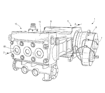
[0015] FIGS. 1 and 2 illustrate a pump 1 including a drive-end 5 and a
fluid-end 10. The
drive-end 5 includes a housing 6, a crankshaft 7 rotatably supported with the
housing 6, and a
gear train 8 to drive the crankshaft 7 via a motor. The drive-end 5 further
includes a connecting
3
CA 2970467 2017-06-12
rod 9 eccentrically mounted to the crankshaft 7. The fluid-end 10 includes a
housing 15 that
couples to the housing 6 of the drive-end 5.
[0016] With reference to FIGS. 3 and 4, formed within the housing 15 is a
plurality of
plunger bores 20, a plurality of discharge bores 25, a plurality of valve
cover bores 30, and a
plurality of inlet bores 35. The fluid-end 10 also includes plungers 40 that
are disposed within
each one of the plunger bores 20 (FIG. 2). The plungers 40 may also be
referred to as pistons or
other reciprocating members in other embodiments. The plunger bores 20 each
define a plunger
axis 45. Each inlet bore 35 defines inlet axes 60 and are in communication
with a fluid inlet 50.
The inlet axes 60 are perpendicular and intersect the plunger axes 45. The
respective bores 20,
25, 30, 35 converge to a common intersection, referred to as cross-bore
intersections 55. Each
discharge bore 25 defines discharge axes 65 and are in communication with a
fluid outlet 70.
The discharge axes 65 are coaxial with the inlet axes 60.
[0017] The fluid-end 10 of the illustrated embodiment is formed as a
monolithic component
via single casting, forging, or other suitable process. In other embodiments,
the fluid-end 10
may be formed as multiple pieces via machining, casting, and forging
processes. Each of the
plunger bores 20, discharge bores 25, valve cover bores 30, inlet bores 35,
and cross-bore
intersections 55 are substantially identical and therefore only one plunger
bore 20, discharge bore
25, valve cover bore 30, inlet bore 35, and cross-bore intersection 55 will be
subsequently
described for sake of convenience and brevity.
[0018] With reference to FIGS. 1 and 2, the valve cover bore 30 includes a
threaded region
75 to threadably engage a cover 80. The cover 80 is therefore removably
coupled to the valve
cover bore 30 along a valve cover axis 85. In other embodiments, the cover 80
may be
removably connected to the valve cover bore 30 through other fastening means.
When the cover
80 is removed from the valve cover bore 30, an operator can access and
maintenance
components disposed within the housing 15 of the fluid-end 10.
100191 With continued reference to FIGS. 4 and 5, the plunger bore 20
interfaces with the
cross-bore intersection 55 via a plunger port 90. Similarly, the valve cover
bore 30 interfaces
with the cross-bore intersection 55 via a valve cover port 95. The plunger
port 90 and the valve
4
CA 2970467 2017-06-12
cover port 95 each define a transition area 100, 105 that smooths potential
sharp corners between
the bores 20, 30 and the cross-bore intersection 55. As a result of the
transition areas 100, 105,
stresses at the cross-bore intersection 55 are decreased.
[0020] Similarly, a V-shaped groove 110 of the inlet bore 35 is disposed
adjacent the cross-
bore intersection 55 and also decreases stress at the cross-bore intersection
55. The V-shaped
groove 110 traverses along a curvilinear path between the plunger transition
area 100 and the
valve cover transition area 105. Also, the V-shaped groove 110 extends around
the inlet axis 60.
100211 With reference to FIG. 6, the inlet bore 35 is further defined by an
interior wall 115.
The interior wall 115 has a contour when viewed in a cross section taken along
line 4-4 of FIG.
3. The contour is revolved around the inlet axis 60, such that the contour is
substantially
identical when viewed in a cross section taken normal to the plunger axis 45
(FIG. 7). As shown
in FIG. 6, the contour includes a concave or cylindrical portion 120 that is
arranged parallel to
the inlet axis 60.
100221 With continued reference to FIG. 6, the contour of the interior wall
115 further
includes a planar portion 125 that extends in a direction normal to the inlet
axis 60. The planar
portion 125 is adjacent the fluid inlet 50 and is spaced a first distance DI
away from the plunger
axis 45. A fillet portion 130 of the interior wall 115 interconnects the
cylindrical portion 120 and
the planar portion 125, such that the cylindrical and planar portions 120, 125
tangentially
converge to form a concavity.
[00231 The interior wall of the illustrated embodiment further includes a
convex bulge
portion 135 extending from the cylindrical portion 120. Particularly, the
convex bulge portion
135 is interposed between the cylindrical portion 120 and the V-shaped groove
110. The convex
bulge portion 135 tangentially converges with the V-shaped groove 110 and the
cylindrical
portion 120. The convex bulge portion 135 is spaced a second distance D2
relative to the
plunger axis 45 that is less than the first distance DI. Essentially, the
convex bulge portion 135
extends radially inward from the V-shaped groove 110 and the cylindrical
portion 120.
100241 With reference to FIG. 6, the interior wall 115 creates a stress
reducing taper angle
140. The taper angle 140 is defined between the valve cover axis 85 and the
surface where the
CA 2970467 2017-06-12
V-shaped groove 110 and the convex bulge portion 135 tangentially converge.
The taper angle
140 is an obtuse angle such that the taper angle 140 is above 90 degrees. The
taper angle 140 is
generally greater than 90 degrees and less than 150 degrees. More
specifically, the taper angle
140 is 120 degrees.
[00251 In one specific embodiment of the invention, at an outermost radial
extent of the V-
shaped groove 110 relative to the inlet axis 60, the V-shaped groove 110 is
spaced between 70
mm to 99 mm away from the inlet axis 60. Specifically, the V-shaped groove 100
is spaced 73.4
mm away from the inlet axis 60 at the outermost radial extent of the V-shaped
groove 110.
Furthermore, at an outermost radial extent (i.e., radial distance RI) of the
cylindrical portion 120
relative to the inlet axis 60, the cylindrical portion 120 is spaced between
76 mm to 101 mm
away from the inlet axis 60. Specifically, the radial distance RI of the
cylindrical portion 120 is
spaced 83.75 mm away from the inlet axis 60 (FIG. 4). Also, at an innermost
radial extent (i.e.,
radial distance R2) of the convex bulge portion 135 relative to the inlet axis
60, the convex bulge
portion 135 is spaced between 60 rum to 98 mm away from the inlet axis 60.
Specifically, the
radial distance R2 of the convex bulge portion 135 is spaced 70.6 mm away from
the inlet axis
60 (FIG. 4).
[00261 In operation, each plunger 40 reciprocates along the plunger axis 45
of each plunger
bore 20. As each plunger 40 reciprocates along the plunger axes 45, away from
the valve cover
bore 30, fluid is drawn into each inlet bore 35 through the fluid inlet 50.
Subsequently, the fluid
passes into cross-bore intersections 55 along the inlet axes 60. At this
point, each plunger 40
reciprocates along the plunger axes 45, toward the valve cover bore 30, which
causes the fluid to
exit the fluid-end 10 of the pump through each discharge bore 25 along the
discharge axes 65.
Specifically, the fluid exits through the fluid outlet 70 disposed within the
discharge bore 25.
Each plunger continuously reciprocates along the plunger axes 45 to draw fluid
into the fluid-end
and to eject the fluid from the fluid-end 10.
6
CA 2970467 2017-06-12
[0027]
Thus, the invention provides, among other things, an interior wall 115 of an
inlet bore
35 having a geometry to reduce stresses on a fluid-end 10 of a pump caused by
fluidic pressures.
The invention minimizes operating stresses in the lower quadrant (or
hemisphere) of the cross-
bore intersection 55. The invention improves the fatigue life of the fluid-end
10 of the pump.
The taper angle 140 tends to reduce the stress concentration at the cross-bore
intersection 55 by
blending the geometry of the inlet bore 35 and better distributing the load
around the cross-bore
intersection 55. Various features and advantages of the invention are set
forth in the following
claims.
7
CA 2970467 2017-06-12