Note: Descriptions are shown in the official language in which they were submitted.
Automated Pig Launching System
FIELD OF THE DISCLOSURE
[0002] This subject matter of the present disclosure relates to
devices and
methods for launching pipeline pigs. More specifically, the disclosed subject
matter relates to a system and methods for staging multiple pigs of any type
and launching them individually with a fully-automated, semi-automated, or
manually-operated pig launch system that can be horizontally oriented.
BACKGROUND OF THE DISCLOSURE
(0OO) Pigging systems are installed on pipeline systems for the
purpose of
inserting a pipeline pig without interruption of the pipeline flow. Pipeline
pigs are typically sized to the nominal pipeline diameter and configured of
different designs and materials to serve the purpose of cleaning, liquid
removal, drying, hatching, chemical treatment, or inspection. Traditional
pigging systems (sometimes known as launchers and receivers) have been
utilized for decades to insert and retrieve pipeline pigs without interrupting
the product flow. The launcher is installed upstream in the traditional
pigging system and the receiver unit is installed downstream of the section of
the pipeline to be pigged.
[0004) Fig. 1A illustrates a pig launcher 10 according to the prior
art, and
Figure 1B illustrates a pig receiver 20 according to the prior art. Briefly,
the
launcher 10 has an oversized barrel section 11 connected by an eccentric
reducer 12 to a nominal line section 13. A closure 14 on the barrel section 11
provides access to its interior for inserting a pig (not shown). The line
CA 2970485 2018-11-13
CA 02970485 2017-06-09
WO 2016/094525
PCT/US2015/064727
2
section 13 has a flange 16 for connecting to a line pipe of a piping system.
The barrel section 11 includes a blow-down connection 18A, a kicker
connection 18B, and a drain connection 18C. The line section 13 includes a
pig signaler 15 and a vent 17.
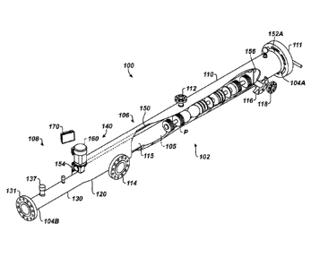
[0005] The receiver 20 is similar and has a nominal line section 23
connected by a concentric reducer 22 to an oversized barrel section 21. A
closure 26 on the barrel section 21 provides access to its interior for
removing pigs (not shown). The line section 23 has a flange 24 for
connecting to a line pipe of the piping system. The barrel section 21 includes
a blow-down connection 28A, a bypass connection 28B, and a drain
connection 28C. The line section 23 includes a pig signaler 25 and a vent 27.
[0006] These units 10, 20 are isolated from the mainline with isolation
valves (not shown) to allow the pressure to be released and the product
drained or vented so that pipeline pigs can be inserted or retrieved from the
pipeline system with no pressure or product in the launcher 10 and receiver
20. Such traditional units 10, 20 of the pigging system as shown in Figs. 1A-
1B are manually operated to launch and receive a single pipeline pig for each
pigging operation.
[0007] Other pigging systems in the art have an automated pig launcher
that can provide improved pipeline flow efficiency, cost savings, and safety
by
not requiring each pig to be loaded individually. To date, automated pig
launchers use a vertical or angled design orientation where the pipeline pigs
are gravity fed to the downstream launch mechanism. In particular, the
existing launch mechanism has two pins that are retracted by means of
hydraulics or pneumatics allowing the pipeline pig to be launched by gravity.
Additionally, current automated pig launchers are designed for a specific type
of pig and product type.
[0008] Because current automated pigging systems are gravity fed, the
systems need to be elevated at an installation. This requires the installation
to have a platform to provide access to the system components and requires
lifting equipment to be used for the operation of the unit. Additionally,
CA 02970485 2017-06-09
WO 2016/094525
PCT/US2015/064727
3
because current automated pigging systems use hydraulics or pneumatics to
actuate launch mechanism, the existing system requires supply gas to drive
the hydraulics, which complicates the installation and its operation. In fact,
the controller for these current automated pigging systems can be complex,
making them harder to operate and maintain.
[0009] The subject matter of the present disclosure is directed to
overcoming, or at least reducing the effects of, one or more of the problems
set forth above.
SUMMARY OF THE DISCLOSURE
[0010] A method and system stages multiple pigs and individually launches
each pig in a fully-automated, semi-automated, or manually operated
manner. The system has a launcher oriented in a horizontal position with a
flow-through barrel and a launch mechanism. In general, the launch
mechanism can be operated by a programmable logic controller, a user-
operated switch, or manual operation.
[0011] In one embodiment, the launch mechanism can use a geared feed
screw system that moves a paddle along the internal length of the oversized
launch barrel to advance the pigs staged in the barrel. The staged pigs are
engaged with the paddle of the geared feed screw launch mechanism, and one
of the pipeline pigs is pushed into a reducer transitioning the larger
diameter
barrel to a pipeline section of the launcher. Differential pressure is created
when the pig seals at least partially in the area of the reducer of the
launcher
located downstream of a flow-through nozzle. The process flow behind the
advanced pig then allows the pig to be launched into the downstream piping.
The gears on the drive mechanism can be manually operated, operated on-
demand, or programed with an independent controller that allows pig
launches to be made at a specific time or time interval.
[0012] The launcher does not require gravity to feed the pigs. Therefore,
the launcher can be positioned horizontal at a site. This has the benefits of
eliminating the need for an elevated platform and associated structures,
lifting
CA 02970485 2017-06-09
WO 2016/094525
PCT/US2015/064727
4
equipment, and the like. In addition, the horizontal arrangement reduces costs
and the complexity of ancillary piping.
[0013] In general, the launch mechanism includes a guide and an actuator.
The mechanism can use a motor, a feed screw, a cable, a cylinder, or other
drive member used in conjunction with a paddle, a cradle, a tray, or the like.
Pigs may also be positioned for launch using a conveyor belt type mechanism.
[0014] In the system, the launcher has a pipeline connection flange through
which process flow normally flows. Pigs are positioned for launch using the
controlled feed of the launch mechanism, which is independent of the
particular pig. The launch and sequencing are not dependent on specific pig
dimensions and can be programmed, thereby allowing the use of pigs of
varying purpose, dimensions, and manufacture. Pigs for differing purpose
and physical size/configuration may be loaded in the same batch. Finally, the
flow-through pipeline connection on the launcher obviates the need for
actuating pipeline valves. This reduces cost and complexity of unit
[0015] In operation, process flow is initially diverted from the launcher,
and
any residual fluid is drained from the launcher. The closure door of the
launcher is opened to provide access to the launcher's chamber. A batch of
pigs is loaded in the launcher, which is then closed and filled with process
flow.
[0016] Pig information and launch requirements are entered into the
controller, and flow is redirected through the launcher. At the programed
time, a pig is fed into the process flow by the launch mechanism and
launched. The pig moves through the pipeline, accomplishes an intended
task, and ultimately enters a receiver. At the programed time, the next pig in
sequence is moved into the process flow and launched to move through
pipeline and then enter the receiver. The sequence can be repeated until an
entire batch of pigs is launched and received. A typical batch quantity can be
about seven pigs.
[0017] The foregoing summary is not intended to summarize each potential
embodiment or every aspect of the present disclosure.
CA 02970485 2017-06-09
WO 2016/094525
PCT/US2015/064727
BRIEF DESCRIPTION OF THE DRAWINGS
[0018] Fig. 1A illustrates a pig launcher according to the prior art.
[0019] Fig. 1B illustrates a pig receiver according to the prior art.
[0020] Fig. 2A illustrates a perspective view of a pig launcher according
to
the present disclosure with flow-through and kicker piping.
[0021] Fig. 2B illustrates a perspective view of the disclosed pig launcher
isolated from the additional piping.
[0022] Fig. 2C illustrates a perspective view of the disclosed pig launcher
with a cutaway showing internal components thereof.
[0023] Fig. 3A illustrates a perspective view of a pig receiver according
to
the present disclosure with flow-through and flow-exit piping.
[0024] Fig. 3B illustrates a perspective view of the disclosed pig receiver
without the additional piping.
[0025] Figs. 4A-4C illustrate details of nozzles disposed on the disclosed
pig
launcher.
[0026] Figs. 5A-5D illustrate embodiments of launch mechanisms for
guiding and mechanically feeding pigs in the disclosed pig launcher.
[0027] Fig. 6A illustrates a gear box for the disclosed pig launcher.
[0028] Fig. 6B illustrates a worm gear feed screw for the disclosed pig
receiver.
[0029] Fig. 6C illustrates a support bearing for the disclosed pig
launcher.
[0030] Fig. 7 illustrates a cross-sectional view of a high pressure seal
for the
worm gear of the disclosed pig launcher.
[0031] Fig. 8 illustrates a launch paddle for the disclosed pig launcher.
[0032] Figs. 9A-9B illustrate perspective and end views of a launch tray
for
the disclosed pig launcher.
[0033] Fig. 10A-10B show example user interface screens for a controller of
the disclosed pig launcher.
DETAILED DESCRIPTION OF THE DISCLOSURE
A. Pigging System
CA 02970485 2017-06-09
WO 2016/094525
PCT/US2015/064727
6
[0034] A pigging system of the present disclosure includes a pig launcher
100 (Figs. 2A-2C) and a pig receiver 200 (Figs. 3A-3B) for a pipeline. As will
be appreciated, a typical pipeline can conduct any type of process flow,
product or non-solid material, such as a gas, a liquid, or a colloidal
suspension capable of being transported through the pipeline. Examples of
products that are transported through a pipeline may include: natural gas,
propane, crude oil, water, and petroleum condensate.
[0035] The pig launcher 100 is assembled on the pipeline from where pigs P
are to be launched to perform an intended task related to pigging. The
launcher 100 is typically placed at the start of a pipeline section to be
pigged.
For its part the pig receiver 200 is assembled on the pipeline to where pigs P
are received after performing their intended tasks related to pigging. The
receiver 200 is typically placed at the end of a pipeline section to be
pigged.
[0036] As is known, a pig P is a device that is inserted into the pipeline
to
perform a specific task. In various embodiments, pigs P may be utilized to
perform tasks that may include: cleaning, liquid removal, drying, batching,
chemical treatment and inspection. A pig may be unidirectional or
bidirectional.
[0037] In Fig. 2A, the pig launcher 100 is shown with additional piping 30,
while the pig launcher 100 is shown in an isolated view in Fig. 2B and is
shown with internal components visible in Fig. 2C. The pig launcher 100 is
used for staging multiple pigs P and launching them individually into a
pipeline (not shown) via an introductory pipe or line L. As discussed below,
operation of the pig launcher 100 can be fully-automated, semi-automated, or
manual, as desired for a particular implementation.
[0038] The pig launcher 100 includes a housing 102 defining a chamber 105
and having an inlet 104A and an outlet 104B. The inlet 104A receives one or
more pigs P into the chamber 105 and is sealable, for example, using a
closure 111, such as a door. The outlet 104B connects in sealed
communication with the process flow in the line L of the piping system 30.
CA 02970485 2017-06-09
WO 2016/094525
PCT/US2015/064727
7
The outlet 104B passes the one or more pigs P out of the chamber 105 to the
process flow.
[0039] Internally as best shown in Fig. 2C, a guide 106 is disposed in the
chamber 105 and guides the one or more pigs P in the chamber 105.
Additionally, an actuator 108 mechanically feeds the one or more pigs P
guided by the guide 106 to the outlet 104B. A portion of the chamber 105 is
in communication with the process flow of the piping system 30 via a number
of connections and valves discussed below.
[0040] In Fig. 3A, the pig receiver 200 is shown with additional piping 40
for flow-through and flow-exit while the pig receiver 200 is shown in an
isolated view in Fig. 3B. The pig receiver 200 includes a nominal line pipe
section 230, a concentric reducer 220, and an oversized barrel section 210.
The receiver's barrel section 210 is of extended length to accommodate
multiple pigs received from the line L to which the receiver 200 is coupled
with an isolation valve 42.
[0041] Looking more closely now at the pig launcher 100 of Figs. 2A-2C, the
housing 102 has an oversized barrel section 110, an eccentric reducer 120,
and a nominal line section 130. A launching mechanism 140 incorporated
into the housing 102 includes the guide 106 and the actuator 108.
[0042] The barrel section 110 is elongated to stage multiple pigs P in its
interior chamber 115. During operation, the launching mechanism 140
launches the pigs P individually into the process flow of the line L to which
the launcher 100 is coupled with an isolation valve 32 at the outlet 104B of
the launcher 100.
[0043] The pig launcher 100 has a horizontally oriented design that
connects by means of a flange connection 131 at the outlet 104B to the
isolation valve 32. The barrel section 110 is oversized in its diameter, which
allows for flow to bypass the pigs and relieves any motive force. For example,
the diameter of the barrel section 110 may be twice the diameter of the
nominal pipe section 130. The nominal pipe section 130 may be sized to be
twice as long as the nominal pipe diameter. The length of the barrel section
CA 02970485 2017-06-09
WO 2016/094525
PCT/US2015/064727
8
110 may be about 14x the line pipe diameter. The distal end of the barrel
section 110 either has a flanged connection at the inlet 104A or is prepared
with a weld bevel to install a quick opening closure 111 or other access
fitting
to allow access for loading pigs P into the barrel section 110.
[0044] As noted above, portion of the chamber 105 is in communication
with the process flow of the piping system 30 via a number of connections
and valves. In particular, a blow-down nozzle or port 112 (shown in detail in
Fig. 4A) is disposed toward the top of the housing 110 and communicates
with the chamber 115 near the inlet 104A. The blow-down nozzle 112 is
used for depressurizing the chamber 115.
[0045] A flow-through nozzle or port 114 (shown in detail in Fig. 4B) is
located on the barrel section 110 and is oriented horizontally, one nominal
pipe diameter upstream of the distal end of the eccentric reducer 120. The
area of the housing 102 upstream from the flow-through nozzle 114 to the
outlet 104B forms a flow-through section where process flow continuously
flows as part of the launcher's operation.
[0046] Finally, a kicker nozzle or port 116 and a drain nozzle or port 118
(both shown in detail in Fig. 4C) communicate with the chamber 115 near the
inlet 104A. The kicker nozzle 116 is disposed toward the side of the housing
110 and is used for providing a kick of fluid into the chamber 115 when
launching a specialized pig that is not launched automatically. The drain
nozzle 118 comes off the bottom of the housing 102 and is used for draining
the chamber 115 of fluid.
[0047] In the present embodiment, the integrated components of the launch
mechanism 140 include a worm gear feed screw 150, one or more bearing
assemblies 152, a launch paddle 156, a gear box 154, a motor 160, and a
controller 170. Some details of the feed screw 150, the paddles 156, etc. are
shown in Fig. 2C. Details of the launch mechanism 140 are discussed further
below.
[0048] In one advantage, the pig launcher 100 is horizontally oriented,
which eliminates the need for elevated platforms required to insert the pigs
CA 02970485 2017-06-09
WO 2016/094525
PCT/US2015/064727
9
P. Additionally, the oversized barrel section 110 and the pipe section 130 of
the launcher 100 (as well as the receiver) are longer for the purpose of
launching and receiving multiple pigs P. In particular, the tubular barrel
section 110 is elongated to accommodate a series of pipeline pigs P loaded
end-to-end to stage their introduction into the pipeline system. Moreover,
the disclosed launching mechanism 140 can be adapted to accommodate a
various number of pigs P and is not restricted to a specific pig type to be
used,
launch interval, or pipeline product.
B. Launch Mechanisms
[0049] The launch mechanism 140 introduces (launches) the pipeline pigs P
one at a time into the line L of the pipeline system. As noted above, the
launch mechanism 140 in Figs. 2A-2C includes the worm gear feed screw 150
installed inside the elongated barrel section 110. This is represented again
more schematically in a transparent view of the launcher 100 in Fig. 5A.
[0050] The feed screw 150 is installed at the 12 o'clock position in the
barrel section 110 and extends the entire length of the elongated section 110.
The feed screw 150 (an example of which is shown in Fig. 6B) can be
composed of stainless steel. At its distal end toward the inlet 104A of the
barrel section 110, the worm gear feed screw 150 is attached to the barrel
section 110 by means of a bearing assembly 152A, which attaches the feed
screw 150 to the internal wall of the oversized barrel section 110.
[0051] The bearing assembly 152A can be a pillow block, such as shown in
Fig. 6C, which is connected to the barrel section 110 to support the distal
end
of the worm gear feed screw 150. The feed screw 150 extends to the
proximal end of the over-sized barrel section 110 at the 12 o'clock position
and can connect to a secondary bearing assembly 152B. Then at the eccentric
reducer 120, the feed screw 150 exits the housing 102 with a high pressure
seal 158, such as shown in Fig. 7.
[0052] The feed screw 150 extends beyond the high pressure seal 158 and
connects to an output shaft 155B of a gear box 154 (Fig. 6A). An input gear
box shaft 155A (Fig. 6A) can be utilized to install the motor 160 for fully-
CA 02970485 2017-06-09
WO 2016/094525
PCT/US2015/064727
automated or semi-automated embodiments. Alternatively, the gear box
shaft 155A can be hand-operated for manual capabilities.
[0053] Either way, the worm gear feed screw 150 can be rotated
circumferentially within the barrel section 110. Rotation of the feed screw
150 then moves the launch paddle 156 along the feed screw's length so pigs P
can be loaded toward the launch reducer 120. Being internal to the barrel
section 110, the paddle 156 is movably attached to the feed screw 150 by a
threaded coupling 157A (Fig. 8) and travels from the distal end to the
proximal end of the barrel section 110 to push the pipeline pigs P into the
launch reducer 120.
[0054] The motor 160 can be an electric motor, although other drives can
be used. For example, a hydraulic motor can be used, but may require a
pneumatic supply gas to operate/actuate the launch mechanism 140. Most
pneumatic supply gases are provided by natural gas from the pipeline so a
pump can drive the hydraulics. There may be methane emissions as the
pneumatic pump strokes so using an electric motor can eliminate such
methane emissions.
[0055] For automated operation, the motor 160 can be connected to a
controller 170 having a programmable logic controller and a display. The
controller 170 is operable to actuate the motor 160 based on pre-
programmed time intervals, local operation, remote operation, or other
automated control scheme. Further details of any automated operation are
discussed below.
[0056] As noted above, the gear box 154 and the motor 160 are preferably
disposed external to the barrel section 110. Therefore, the connection of the
gear box 154 to the worm gear feed screw 150 passing through the housing's
wall uses the high-pressure seal 158, as shown in Fig. 7. The high pressure
seal 158 seals the extended gear drive mechanism from the internal line
pressure so that it can be operated external to the pressurized side of the
launch mechanism 140.
11
[0057] In general, the seal 158 can be created in several ways,
including but
not limited to one or more of: an 0-ring type seal being of either
conventional
or one of the many existing varieties of cross-section, a lip-type rotary
seal, or
a conventional stuffing box arrangement (e.g., a gland-type of stuffing box
seal). For the gland-type seal, a loosely braided or otherwise deformable
sealing material is layered in a cavity around the shaft of the feed screw 150
passing through the barrel wall. A packing gland/nut, which generates a
large force along the axis of the shaft, is used to compress the seal material
within the cavity causing it to exert pressure against the cavity wall and
shaft
surface. Sufficient force is applied so that the compression forces of the
packing material exceed the pressure being contained and leakage is
prevented. As will be appreciated, the sealing and packing area of the seal
158 can be incrementally increased based on the specified pipeline pressures
and other requirements of an implementation.
[0058] In addition to the feed screw 150, the paddle 156, and other
features
for the launch mechanism 140 to guide and mechanically feed the pigs P
horizontally, other mechanisms can be used. For example, the launch
mechanism 140 can use a motor, a feed screw, a cable, a cylinder, or other
drive member used in conjunction with a paddle, a cradle, a tray, or the like,
Pigs may also be positioned for launch using a conveyor belt type mechanism.
[0059] Although a rotatable feed screw 150 and paddle 156 have been
disclosed above for the launch mechanism 140, other actuators and guides
can be used to move the staged pigs P along the length of the barrel section
110. In this regard, hydraulic or pneumatic cylinders can have arms that
move inside the barrel section 110 and push and/or pull the paddle 156
inside the barrel section 110. The paddle 156 may be supported on rails or
the like. Alternatively, a rack and pinion system could be used. As will be
appreciated with the benefit of the present disclosure, these and other
mechanisms can be used to move the pigs in the launcher 100.
[0060] Fig. 5B shows an example of a launch mechanism 140 having a
motor 160 that rotates a drive belt 151 with a gear 161, Forward and reverse
CA 2970485 2018-11-13
CA 02970485 2017-06-09
WO 2016/094525
PCT/US2015/064727
12
rotation of the gear 161 can move a paddle 156 on the belt 151 back and
forth in the chamber 115 of the barrel section 110. In this way, pigs P can be
individually fed with the belt 151 to the area adjacent the feed-through
nozzle 114 upstream of the line section 130 of the launcher 100.
[0061] Fig. SC shows another example of a launch mechanism 140 having a
motor 160 that moves a linear actuator 153. For example, the motor 160 can
be hydraulic, and the linear actuator 153 can be a piston or the like.
Extension and retraction of the linear actuator 153 can move a paddle 156
back and forth in the chamber 115 of the barrel section 110. In this way, pigs
P can be individually fed with the linear actuator 153 to the area adjacent
the
feed-through nozzle 114 upstream of the line section 130 of the launcher
100.
[0062] Fig. 5D shows yet another example of a launch mechanism 140
having a motor 160 moves a conveyor belt 155 with a gear 165. Forward and
reverse rotation of the gear 165 can move the conveyor belt 151 back and
forth in the chamber 115 of the barrel section 110. In this way, pigs P can be
individually fed with the belt 155 to the area adjacent the feed-through
nozzle 114 upstream of the line section 130 of the launcher 100.
[0063] As the various launch mechanisms 140 disclosed in Figs. 5A-5D will
show, a number of different mechanisms that guide and actuate can move
pigs P in the barrel section 110 and can be used with the launcher 100.
Accordingly, these and other alternatives of the disclosed launch mechanisms
140 can be used. Moreover, discussion herein may refer to the components
of the launch mechanism 140 in Fig. 5A, but not necessarily others as in Figs.
5B-5D. However, it will be appreciated with the benefit of the present
disclosure that features discussed herein can be readily adapted to the
various disclosed launch mechanisms.
C. Launch Tray
[0064] Most commonly, but not always, a launch tray 180 as shown in Figs.
9A-9B can install into the bottom of the barrel section 110 to stage multiple
pipeline pigs P into the launch mechanism 140. The launch tray 180 can be
13
removed from the barrel section 110, loaded with a specific number of pigs P,
and reinserted into the barrel section 110 to stage the pigs P for launching.
In general, the launch tray 180 is a channel in which pigs P are horizontally
placed for staging into the launching mechanism 140.
[0065] The launch tray 180 includes sidewalls 182 and a curved base 184
for resting in the barrel section 110. Guide rails 183 are provided on the
sidewalls 182 to help hold the pigs P on the base 184. Additionally, the guide
rails 183 can allow guide arms, such as arms 157b on the paddle 156 in Fig. 8,
to ride and guide movement of the paddle 156 along the launch tray 180 as
the paddle 156 is moved inside the barrel section 110. Friction guides 185
can also be installed on the sidewalls 182 of the tray 180 to produce friction
on the moving pigs P. This controlled friction from the guides 185, the base
184, etc. on the tray 180 can be used to ensure that only one pig P at the end
of the tray 180 is fed into the reducer 120 at a time during a launch
sequence.
[0066] Depending on the pigs P used, the launch tray 180 may not he
needed, or a particular launch tray 180 may have adjustable components
(e.g., sidewalls 182, guide rails 183, etc.) that allow it to accommodate
different types of pigs. Alternatively, a different launch tray may be used to
accommodate different types of pigs. For example, the launch tray 180 need
not bean open-type of bed with sidewalls 182 and base 184. Instead, the
launch tray 180 can be an elongated canister for staging the pigs P and can be
composed of a perforated aluminum tube or the like having a slot to
accommodate the paddle's passage.
D. Controller/Automation
[0067] As noted above, an external drive mechanism (e.g., gear box 154,
motor 160, etc.) operates the launch mechanism 140. The external drive
mechanism can be operated manually, semi-automatically, and automatically.
In particular, to operate the launch mechanism 140 manually, operators can
manually operate the shaft 155A of the worm gear drive mechanism with a
wrench or a drill motor to actuate the pig paddle 156 towards the reducer
120 to launch a pipeline pig P. In this manual operation, the travel distance
of
CA 2970485 2018-11-13
CA 02970485 2017-06-09
WO 2016/094525
PCT/US2015/064727
14
paddle 156 is controlled by the number of turns made to the extended gear
shaft 155A.
[0068] The launch mechanism 140 can also be operated automatically or
semi-automatically. As noted previously, the gear shaft 155A of the drive
mechanism 154 can be operated with a motor 160, such as an explosion-
proof electric motor, to actuate the launch paddle 156 towards the reducer
120 to launch a pipeline pig P. The electric motor 160 can be controlled
semi-automatically by an operator with an ON/OFF switch to the desired
paddle travel distance. Alternatively, the electric motor 160 can be
controlled automatically by programmed logic of the controller 170.
[0069] In general, the controller 170 can include a control panel, which
can
display control screens to program the specific launch interval, launch time,
remote actuation, or other operation. The controller 170 is programmed in
accordance to the pig type and pig length. In turn, the controller 170
controls
the electric motor 160 and the travel distance of the paddle 156 to launch
pipeline pigs P. In short, the controller 170 controls the actuation of the
launching mechanism 140 for the fully-automated operation.
[0070] The controller 170 can have an Ethernet or other connection to
remotely access the launch mechanism 140 to monitor performance and/or
control the launching of a pipeline pig P. The controller 170 also operates as
a terminal to monitor pig passages with a signal receiver from a remote pig
signaler, and the controller 170 can monitor the amperage during operation
of the launcher 100, among other monitoring operations.
[0071] The controller 170 may have connections to (or may use any signals
from) flow sensors, pig detectors, or other sensing equipment, and the
controller 170 can use such signals to control operation of the launcher 100
automatically. For example, the controller 170 can have a number of
auxiliary terminals to provide various functions. In particular, the
controller
170 can use a pig signaler 137 located on the nominal pipe section 130
immediately downstream of the eccentric reducer 120. Signals from the
CA 02970485 2017-06-09
WO 2016/094525
PCT/US2015/064727
signaler 137 can be used by the controller 170 to validate passage of a pig P
whenever the launch mechanism 140 has launched a pig P.
[0072] The controller 170 may also receive a signal from a signaler located
downstream of the mainline isolation valve 32 attached to the pig launcher
100 to validate a pig's passage, and the controller 170 can use that
information to determine that the pig is traversing the pipeline L whenever
the launch mechanism 170 has launched a pig P. Additionally, the controller
170 can have a terminal connection to a remotely-operated valve that can act
as a fail-safe mechanism. In this sense, the controller 170 can automatically
shut-off the pig launcher 100 any time that the mainline isolation valve 32 is
closed.
[0073] Figs. 10A-10D illustrate example user interface screens 176a-d for
programming the controller 170 to operate the disclosed launcher 100. In
Fig. 10A, the first screen 176a shows an example of how an operator can set
the number of pigs P to be loaded in the launcher 100. The length of each pig
P can be input, should different length pigs P be used. The timing of the
launch for the various pigs P can also be input. The number of pigs P in the
barrel section 100 and the position of the paddle 156 inside the section 100
can be known and displayed. Manual mode or over-ride controls may also
allow operators to manually move the paddle 156 back and forth.
[0074] The screen 176b in Fig. 10B shows some input and control
information of the controller 170. The screen 176c in Fig. 10C shows how an
operator can set different launch intervals for the various pigs P and can set
when a first launch is to take place. Finally, the screen 176d in Fig. 10D
shows how the length of a given pig P can be input so the controller 170 can
track the position of the pig P in the section 110 and the needed movement of
the paddle 156 and the like to launch the pig P.
[0075] As these user interface screens 176a-d will show, the controller 170
of the present disclosure can be programmed in a number of ways and with a
number of inputs to control operation of the disclosed launcher 100. As will
be appreciated, these and other inputs and controls can be used.
16
E. Operation
(00761 In operation, the pig launcher 100 can stage multiple pipeline
pigs P
from the horizontally-oriented pig launch mechanism 140 and can launch a
single pig P from the housing 102 in liquid and gas service from its
horizontal
orientation. The launch mechanism 140 can be fully-automated, semi-
automated, or manually-operated and can launch various types of pigs P on a
controlled basis.
[00771 For fully-automated operation, operators can program the
controller
170 to operate the electric gear-operated pig launch mechanism 140 based
on pipeline pig length and other factors. In this way, the launcher 140 can
launch a single pig P and can stage multiple pipeline pigs P even in low flow
conditions.
[0078] With an understanding of the pig launcher 100 and its
components,
particular discussion is provided on the operation of the launcher 100 to
launch pigs for a pigging operation. Initially, all valves must be in the
closed
position to initiate the operation of the pig launching mechanism 140. For
example, the closed valves on the housing 102 as in Fig. 2A include the
mainline isolation valve 32, the flow-through valve 34 for the flow-through
nozzle 114, the blow-down valve 38 for the blow-down nozzle 112, the kicker
valve 36 for the kicker nozzle 118, and the drain valve (not shown) for the
drain nozzle 116. The pig launching sequence is initiated by opening the
access door 111 located at the input 104A of the over-sized barrel section
110 after the pressure has been relieved from the entire launch system by
opening the system's blow-down nozzle 112 located at the 12 o'clock
orientation.
[00791 The launch paddle 156 is removed from the feed screw 150, and the
launch tray 180, if used, is removed at the inlet 104A from the over-sized
barrel section 110 in the distal direction. Pigs P are loaded into the launch
tray 180, and the launch tray 130 is reinserted into the over-sized barrel
section 110. If a launch tray 180 is not used, the pigs Pare loaded directly
into the over-sized barrel section 110.
CA 2970485 2018-11-13
CA 02970485 2017-06-09
WO 2016/094525
PCT/US2015/064727
17
[0080] The access door 111 is closed, then the valve 38 for the blow-down
nozzle 112 is closed to allow for pressurization of the launcher 100. The
flow-through valve 34 is slowly opened to equalize the pressure between the
launcher 100 and the line L. The flow-through nozzle valve 34 will remain in
the "open" position throughout the duration of the operation of the launch
mechanism 140. Once the pressure has equalized in the automated launcher
100, the mainline valve 32 is opened.
[0081] In preparation of the operation, the controller 170 can be
programmed for fully-automated operation, as shown by the example screens
176 in figure 13. The pig length, number of pigs, schedule for the first pig
launch, and the interval for subsequent launches are entered into the
controller 170. The controller 170 will actuate a pig of a specific length at
the
scheduled time based on the travel distance of the launch paddle 156 in the
proximal direction into the eccentric reducer 120.
[0082] Alternatively, semi-automated launch operations can be performed
by activating the electric motor 160 for a predetermined period based on the
measured pig length and travel distance of the launch paddle 156 in the
proximal direction into the eccentric reducer 120. In this semi-automated
operation, the launcher 100 does not necessarily need to be equipped with a
controller 170 since the semi-automated function can be operated with the
motor 160 to actuate the mechanical launch mechanism 140.
[0083] As noted previously, manual operation can also be performed by
turning the gear box shaft 155A the appropriate revolutions to actuate the
launch paddle 156 the measured length of one pig P in the proximal direction
to the eccentric reducer 120. For a manually operated implementation, the
launcher 100 does not require a motor 160 or a controller 170 since the
launcher 100 is hand-operated to actuate the mechanical launch mechanism
140.
[0084] The foregoing description of preferred and other embodiments is
not intended to limit or restrict the scope or applicability of the inventive
concepts conceived of by the Applicants. It will be appreciated with the
CA 02970485 2017-06-09
WO 2016/094525
PCT/US2015/064727
18
benefit of the present disclosure that features described above in accordance
with any embodiment or aspect of the disclosed subject matter can be
utilized, either alone or in combination, with any other described feature, in
any other embodiment or aspect of the disclosed subject matter.
[0085] Although the pig launcher 100 has been described as being used
horizontally at an installation, this is not strictly necessary since the
launcher
100 can be used in other orientations and can even be angled. In fact, it is
contemplated that the launcher 100 can be oriented vertically with the
paddle 156 moving the pigs P upward to the pipeline or downward to the
pipeline. If fed upward, the angled or vertical launcher 100 may not require
much alteration to accommodate individually introducing the pigs P to the
pipeline. However, if fed downward, a hydraulic mechanism (pin or the like)
may be needed to stop the advance of the pigs P in the angled or vertical
launcher 100.
[0086] In exchange for disclosing the inventive concepts contained herein,
the Applicants desire all patent rights afforded by the appended claims.
Therefore, it is intended that the appended claims include all modifications
and alterations to the full extent that they come within the scope of the
following claims or the equivalents thereof.