Note: Descriptions are shown in the official language in which they were submitted.
WO 2016/094811
PCT/US2015/065269
MULTIPLACE HYPERBARIC CHAMBER SYSTEMS AND METHODS
PRIORITY CLAIM
The present application claims the benefit of U.S. Patent Application
Serial No. 62/090,620, filed December 11,2014.
TECHNICAL FIELD
The subject matter disclosed herein relates generally to pressure
chambers. More particularly, the subject matter disclosed herein relates to
hyperbaric or hypobaric chambers configured to artificially reproduce
pressures different than normal atmospheric pressure.
BACKGROUND
Hyperbaric medicine, also known as hyperbaric oxygen therapy
(HBOT), is the medical use of oxygen at a level higher than atmospheric
pressure (e.g., at 1-1/2 to 3 times normal atmospheric pressure). The
equipment required typically includes a pressure chamber, which may be of
rigid or flexible construction, and a system for delivering 100% oxygen.
Operation is performed to a predetermined schedule by trained personnel
who monitor the patient and can adjust the schedule as required. HBOT has
found early use in the treatment of decompression sickness, and it has also
shown effectiveness in treating conditions such as gas gangrene and carbon
monoxide poisoning. More recent research has examined the possibility that
it may also have value for other conditions such as arterial gas embolism,
necrotic soft tissue infections, crushing injuries, traumatic brain injuries,
cerebral palsy, and multiple sclerosis, among others.
HBOT is usually delivered in monoplace chambers, which are
generally only big enough for a single patient. A few hospitals and
specialized centers around the world have multiplace chambers, which are
big enough for several patients and/or an attendant. All existing chamber
designs exhibit significant drawbacks, however, including high cost and
limited interior space (even in multiplace chambers). As a result, the cost
-1-
Date Recue/Date Received 2022-03-17
WO 2016/094811
PCT/US2015/065269
and availability of such systems are prohibitive for many individuals who may
benefit from hyperbaric therapy.
Accordingly, it would be desirable to provide hyperbaric chamber
systems that can be produced in a more cost-effective manner while still
being able to effectively provide the atmospheric conditions recommended
for hyperbaric therapies.
SUMMARY
In accordance with this disclosure, devices, systems and methods for
the construction of pressure chambers are provided. In one aspect, a
pressure chamber system is provided in which a plurality of substantially
rigid panels are arranged around a space, each of the plurality of
substantially rigid panels comprising a metal frame formed from a plurality of
elongated beam elements, wherein each of the plurality of elongated beam
elements is formed from a plurality of metal frame elements. One or more
connecting plate is coupled to adjacent pairs of the plurality of
substantially
rigid panels, and a pressure differential generator is configured to control
pressure within the space to be different than an atmospheric pressure
outside of the space. In such a system, the one or more connecting plate is
configured to provide a pressure-tight seal between a respective adjacent
pair of the plurality of substantially rigid panels.
In one embodiment, the metal frame of one or more of the plurality of
substantially rigid panels surrounds a core material.
In one embodiment, the core material comprises a polymer core.
In one embodiment, the plurality of elongated beam elements are
connected together in a stacked array.
In one embodiment, the plurality of metal frame elements comprises a
plurality of roll-formed steel frame elements.
-2-
Date Recue/Date Received 2022-03-17
WO 2016/094811
PCT/US2015/065269
In one embodiment, each of the plurality of roll-formed steel frame
elements comprises a substantially C-shaped beam element having a
double lip structure at edges of each of the plurality of roll-formed steel
frame elements.
In one embodiment, one or both of the plurality of substantially rigid
panels or the one or more connecting plate is shaped to maintain a sealing
relationship between the respective substantially rigid panels and the one or
more connecting plate upon deflection of the plurality of substantially rigid
panels under pressurization of the space.
In one embodiment, edges of the one or more connecting plate are
tapered such that the one or more connecting plate lies substantially flush
with coupled edges of the adjacent pairs of the plurality of substantially
rigid
panels upon deflection of the plurality of substantially rigid panels.
In one embodiment, the one or more connecting plate comprises a
first connecting plate coupled to a first surface of a respective adjacent
pair
of the plurality of substantially rigid panels, and a second connecting plate
coupled to a second surface of a respective adjacent pair of the plurality of
substantially rigid panels substantially opposing the first surface.
In one embodiment, the pressure chamber system comprises one or
more coupling elements configured for coupling the first connecting plate
and the second connecting plate to the respective adjacent pair of the
plurality of substantially rigid panels, wherein the one or more coupling
elements comprises a coupling member configured for positioning within
each of the plurality of substantially rigid panels, the coupling member
having a first end and an opposing second end, a first fastener configured to
be received in the first end of the coupling member, the first fastener being
configured to couple the first connecting plate to the first surface of one of
the plurality of substantially rigid panels, and a second fastener configured
to
be received in the second end of the coupling member, the second fastener
-3-
Date Recue/Date Received 2022-03-17
WO 2016/094811
PCT/US2015/065269
being configured to couple the second connecting plate to the second
surface of one of the plurality of substantially rigid panels.
In one embodiment, the coupling member comprises a first threaded
opening at the first end configured for receiving the first fastener, wherein
the first fastener comprises a threaded end, a second threaded opening at
the second end configured for receiving the second fastener, wherein the
second fastener comprises a threaded end, and a pressure-tight barrier
within the coupling member between the first threaded opening and the
second threaded opening.
In one embodiment, the pressure chamber comprises one or more
tension elements connected across the space between a subset of the
plurality of substantially rigid panels.
In one embodiment, the pressure chamber system comprises one or
more elastomeric sealing elements positioned between the one or more
connecting plate and each of the respective adjacent pair of the plurality of
substantially rigid panels.
In one embodiment, the pressure chamber system comprises a
structural building frame to which the plurality of substantially rigid panels
are connected around the space, wherein the structural building frame is
configured to support structural loads of the pressure chamber, and wherein
the plurality of substantially rigid panels are configured to support pressure
loads acting on the pressure chamber.
In another aspect, an assembly of substantially rigid panels for a
pressure chamber system comprises a plurality of substantially rigid panels
arranged around a space, each of the plurality of substantially rigid panels
comprising a plurality of elongated beam elements formed from a plurality of
metal frame elements, and one or more connecting plate coupled to
adjacent pairs of the plurality of substantially rigid panels. The one or more
-4-
Date Recue/Date Received 2022-03-17
WO 2016/094811
PCT/US2015/065269
connecting plate is configured to provide a pressure-tight seal between a
respective adjacent pair of the plurality of substantially rigid panels.
In one embodiment, the metal frame of one or more of the plurality of
substantially rigid panels surrounds a core material.
In one embodiment, the plurality of elongated beam elements are
connected together in a stacked array.
In one embodiment, the plurality of metal frame elements comprises a
plurality of roll-formed steel frame elements.
In one embodiment, each of the plurality of roll-formed steel frame
elements comprises a substantially C-shaped beam element having a
double lip structure at edges of each of the plurality of roll-formed steel
frame elements.
In yet another aspect, a method for constructing a pressure chamber
is provided. The method can comprise forming a plurality of elongated beam
elements from a plurality of metal frame elements, forming a plurality of
substantially rigid panels, each of the plurality of substantially rigid
panels
comprising a metal frame formed from the plurality of elongated beam
elements, arranging the a plurality of substantially rigid panels around a
space, coupling adjacent pairs of the plurality of substantially rigid panels
using one or more connecting plate, wherein the one or more connecting
plate is configured to provide a pressure-tight seal between a respective
adjacent pair of the plurality of substantially rigid panels, and connecting a
pressure differential generator in communication with the space to control
pressure within the space to be different than an atmospheric pressure
outside of the space.
-5-
Date Recue/Date Received 2022-03-17
WO 2016/094811
PCT/US2015/065269
In one embodiment, forming a plurality of substantially rigid panels
comprises connecting the plurality of elongated beam elements in a stacked
array to form each of the plurality of substantially rigid panels.
In one embodiment, the plurality of metal frame elements comprises a
plurality of roll-formed steel frame elements.
In one embodiment, the metal frame of one or more of the plurality of
substantially rigid panels surrounds a core material.
In one embodiment, the method further comprises connecting a
structural building frame to the plurality of substantially rigid panels
around
the space, wherein the structural building frame is configured to support
structural loads of the pressure chamber, and wherein the plurality of
substantially rigid panels are configured to support pressure loads acting on
the pressure chamber.
Although some of the aspects of the subject matter disclosed herein
have been stated hereinabove, and which are achieved in whole or in part
by the presently disclosed subject matter, other aspects will become evident
as the description proceeds when taken in connection with the
accompanying drawings as best described hereinbelow.
BRIEF DESCRIPTION OF THE DRAWINGS
The features and advantages of the present subject matter will be
more readily understood from the following detailed description which should
be read in conjunction with the accompanying drawings that are given
merely by way of explanatory and non-limiting example, and in which:
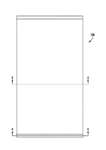
Figure 1 is a top view of a substantially rigid panel for use as a
structural element in a pressure chamber according to an embodiment of the
presently disclosed subject matter;
-6-
Date Recue/Date Received 2022-03-17
WO 2016/094811
PCT/US2015/065269
Figure 2 is a sectional side view of a substantially rigid panel for use
as a structural element in a pressure chamber taken along section line 2-2 of
Figure 1;
Figure 3 is a detailed side view of the substantially rigid panel shown
in Figure 2;
Figure 4 is a sectional side view of a substantially rigid panel for use
as a structural element in a pressure chamber taken along section line 4-4 of
Figure 1;
Figure 5 is a perspective side view of a beam element for use as a
component of a substantially rigid panel in a pressure chamber according to
an embodiment of the presently disclosed subject matter;
Figures 6 and 7 are perspective side views of metal frame elements
for use as a component of a substantially rigid panel in a pressure chamber
according to embodiments of the presently disclosed subject matter;
Figure 8 is a top view of a sheet element for use as a component of a
substantially rigid panel in a pressure chamber according to an embodiment
of the presently disclosed subject matter;
Figures 9 and 10 are side cutaway views of connection plate
assemblies for use in joining substantially rigid panels in a pressure chamber
according to embodiments of the presently disclosed subject matter;
Figure 11 is a side perspective view of a coupling block for use in
joining substantially rigid panels in a pressure chamber according to
embodiments of the presently disclosed subject matter;
Figures 12 and 13 are side cutaway views of connection plate
assemblies for use in joining substantially rigid panels in a pressure chamber
according to embodiments of the presently disclosed subject matter;
Figures 14 and 15 are top views of arrangements of structural beams
of a support structure for a pressure chamber according to embodiments of
the presently disclosed subject matter;
Figure 16 is a side perspective view of a support structure for a
pressure chamber according to an embodiment of the presently disclosed
subject matter;
-7-
Date Recue/Date Received 2022-03-17
WO 2016/094811
PCT/US2015/065269
Figure 17 is a side perspective view of a pressure chamber according
to an embodiment of the presently disclosed subject matter; and
Figure 18 is a flow chart illustrating a method for monitoring building
health of a pressure chamber according to an embodiment of the presently
disclosed subject matter.
DETAILED DESCRIPTION
The present subject matter provides systems, devices, and methods
for pressure chambers (e.g., hyperbaric or hypobaric chambers) configured
to artificially reproduce pressures different than normal atmospheric
pressure. In one aspect, for example, the present subject matter provides a
large pressure chamber constructed using a modular assembly of
substantially rigid panels (e.g., light-gauge steel frame panels).
Particularly,
the pressure chamber can comprise a plurality of substantially rigid panels
coupled together in a substantially pressure-tight arrangement around a
space.
In one non-limiting configuration illustrated in Figures 1-8, the
substantially rigid panels include a metal frame. As shown in Figures 1-4,
for example, substantially rigid panels, generally designated 100, can be
formed from one or more substantially rigid structural elements. In
particular, as shown in Figures 2-5, the structural elements can comprise
elongated beam elements 110 that are formed from one or more metal
frame elements 120. In some embodiments, for example, metal frame
elements 120 can comprise steel elements (e.g., roll-formed steel elements)
similar to those used in light steel framing applications. In this regard,
metal
frame elements 120 can comprise light gauge steel elements (e.g., having
thicknesses less than 0.125 inches). Specifically, in some particular
embodiments, metal frame elements 120 can have thicknesses between
about 0.030 inches and 0.125 inches, with some configurations providing a
desirable balance of weight, structural integrity, and strength (e.g., 50 ksi
minimum yield strength) with thicknesses less than 0.075 inches).
In some exemplary embodiments shown in Figures 6 and 7, frame
elements 120 can have any of a variety of cross-sectional configurations that
-8-
Date Recue/Date Received 2022-03-17
WO 2016/094811
PCT/US2015/065269
can be selected based on a balance of factors. Specifically, Figure 6
illustrates on exemplary configuration in which each of frame elements 120
has a substantially C-shaped cross-sectional profile including a web 122
(e.g., about 10 inches wide) and a pair of flanges 123 that each extend from
opposing sides of web 122 in a direction substantially perpendicular to the
plane of web 122 and are substantially parallel to one another. Further, in
the embodiment shown in Figure 6, each of flanges 123 has a substantially
J-shaped profile that includes a side 124, a lip 125 extending inwardly from
side 124 (i.e., from an end of side 124 substantially opposite from the end to
which side 124 connected to web 122) in a direction substantially parallel to
web 122, and a turned end 126 extending from lip 125 in a direction
substantially parallel to side 124. This arrangement can provide enhanced
resistance to bending and/or buckling. In this regard, frame elements 120
can be configured to contribute to improved strength and rigidity of
substantially rigid panels 110 to allow the pressure chamber to bear the
expected loads encountered under operating pressures, which can be
comparatively extreme compared to conventional structural loads.
Alternatively, Figure 7 illustrates a further configuration in which flange
123
only includes two sides 124. This configuration can be generally less
resistant to bending but can be more readily manufactured. Thus, the
particular configuration for the individual frame elements 120 can be
selected to address the design considerations for a given system.
Regardless of their particular form, frame elements 120 can be
coupled together to define beam elements 110. In the embodiments shown
in Figures 2-5, for example, a pair of frame elements 120 is joined at their
flanges 123 (e.g., for the configuration shown and described with respect to
Figure 6, two frame elements 120 can be joined by coupling their respective
lips 125 together). A plurality of beam elements 110 can then be coupled
together to define panels 100. (See, e.g., Figures 1-4, where an array of
beam elements 110 are coupled together to define a panel 100 having
dimensions of about 6 feet wide by 12 feet tall)) As illustrated in Figures 2-
4,
for example, adjacent pairs of beam elements 110 can be coupled together
at their respective webs 122 in a back-to-back configuration. Alternatively,
-9-
Date Recue/Date Received 2022-03-17
WO 2016/094811
PCT/US2015/065269
those having skill in the art will recognize that beam elements 110 can be
coupled to one another in other arrangements to form panels 100. (e.g., a
web 122 of one of beam elements 110 connected to flanges 123 of an
adjacent one of beam elements 110) As shown in Figure 8, in some
embodiments, beam elements 110 can be further coupled by planar sheet
elements 130 (e.g., 0.054 inch sheet steel), which can be arranged across
the stacked array of beam elements 110.
In some embodiments, beam elements 110 are coupled to one
another and/or to planar sheet elements 130 by fasteners (e.g., blind self-
sealing rivets) at a variety of beam connection points 112 in a manner
substantially similar to the construction of aircraft. Sheet elements 130 can
likewise be connected to beam elements 110 by fasteners at sheet
connection points 132 (see Figure 8), which can in some embodiments
correspond to beam connection points 112. Alternatively, any of a variety of
other known connection mechanisms (e.g., spot welding) can be used to
create panels 100. In some particular configurations, beam and sheet
connection points 112 and 132 at which beam elements 110 are connected
are arranged in an optimized pattern (See, e.g., Figures 5 and 8), which can
distribute load over the connected surfaces, minimize stresses at the
connection points 112 and 132, and/or otherwise improve the structural
performance of panels 100.
Furthermore, additional strengthening can be added to the tension-
side of each of beam elements 110 by inserting a cap track 114 (e.g., having
a thickness of about 0.043 inch) within one or more of beam elements 110
against the inner surface of one (or both) of flanges 123 of each
substantially
C-shaped frame element 120 as shown in Figures 2-4. In some
embodiments, to further reinforce the strength and rigidity of panels 100,
beam elements 110 can be filled with a core material 140, such as a polymer
core material (e.g., polyurethane fill). In some embodiments, for example,
core material 140 can be selected to further provide for added thermal
resistance and/or to help decrease sound transmission.
Regardless of the particular configuration, multiple panels 100 can be
coupled together to define a pressure chamber 200 as discussed above. In
-10-
Date Recue/Date Received 2022-03-17
WO 2016/094811
PCT/US2015/065269
this regard, the interconnection of panels 100 can include one or more
features configured to maintain a pressure seal between panels 100.
Specifically, for example, as illustrated in Figures 9 and 10, one or more
connecting plate 150 can be configured to provide a substantially pressure-
tight seal between a respective adjacent pair of panels 100. In particular, a
first connecting plate 150 can be coupled to a first surface of a respective
adjacent pair of the plurality of panels 100, and a second connecting plate
150 can be coupled to a second surface of a respective adjacent pair of
panels 100 substantially opposing the first surface.
One or more connecting fastener 152 (e.g., a bolt or screw) can be
used to connect connecting plates 150 to panels 100. In some
embodiments, connecting fastener 152 can include a biasing member 153
(e.g., a spring) configured to exert a force that tends to draw connecting
plate 150 and connected panel 100 together. In this way, connecting
fastener 152 can be kept in a state of tension that helps to maintain the
coupling between connecting plate 150 and panels 100.
In some embodiments, each connecting fastener 152 can be received
by a corresponding coupling block 160 that is formed in, attached to, or
otherwise connected with a respective one of panels 100. For example, in
some embodiments, coupling block 160 can be molded into core material
140. In any configuration, coupling block 160 enables coupling between
connecting fastener 152 to panels 100 without introducing a gap or opening
in panels 100 that could allow pressure to leak across panels 100. In one
particular embodiment shown in Figure 11, for example, coupling block 160
can comprise one or more opening 162 configured to receive a
corresponding connecting fastener 152 (e.g., a threaded opening where
connecting fastener 152 comprises a complementarily threaded bolt).
Furthermore, as in the embodiment shown in Figures 10 and 11,
coupling block 160 can be configured to extend substantially an entire
distance through panel 100 for coupling with connecting fasteners 152 on
either side of panels 100. In such an arrangement, coupling block 160 can
be configured such that each opening 162 terminates within coupling block
160 such that there is no communication between opposing openings 162.
-11-
Date Recue/Date Received 2022-03-17
WO 2016/094811
PCT/US2015/065269
In this regard, a substantially pressure-tight barrier 164 can be provided
within coupling block 160 between openings 162 to help maintain the
pressure differential between the inside and outside surfaces of panels 100.
Alternatively, an individual coupling block 160 can be associated with each
connecting fastener 152.
In addition, in some configurations, panels 100 can be expected to
deflect in response to a pressure differential between the interior and
exterior of pressure chamber 200. For example, in arrangements in which
panels 100 are sized to span large distances (e.g., 6-12 feet in width), which
can help to limit the number of panels 100 needed to define pressure
chamber 200 and accordingly limit the number of inter-panel connections
that need to be sealed, panels 100 can deflect two inches or more for every
six feet of unbounded span. Where panels 100 and connecting plates 150
are assembled to seal against one another in an unpressurized state, such a
deflection can change the relative orientation of the components and open a
gap therebetween.
In this regard, in some embodiments, one or both of the plurality of
panels 100 or the one or more connecting plate 150 can be shaped to
maintain a sealing relationship between the respective substantially rigid
panels and connecting plate upon deflection of the substantially rigid panels
under pressurization of the space. Specifically, to accommodate such
deflection, in the exemplary configurations shown in Figures 9 and 10,
connecting plate 150 can be tapered at one or more of its edges 151 such
that connecting plate 150 lies substantially flush with coupled ends of the
adjacent pairs of the plurality of panels 100 upon deflection of panels 100.
(e.g., in the orientation shown in Figures 9 and 10, pressurization of the
structure can result in a center portion of panels 100 deflecting upwards) In
this way, the shape of one or more connecting plate 150 can be designed
such that when the structure is pressurized to its full operating load,
connecting plate 150 can mate completely with the deflected shape of
panels 100.
Furthermore, in conditions that differ from the fully-loaded operating
condition, the seal along the bearing edge (i.e., at an interface between
-12-
Date Recue/Date Received 2022-03-17
WO 2016/094811
PCT/US2015/065269
connecting plate 150 and one of panels 100) can act as a pivot point and will
not open up with the tapered bearing surface, even upon fluctuations of the
pressure differential that result in deflections of panels 100 (e.g., the
structure can be configured to be loaded to a variety of pressures throughout
the day). To further maintain the seal between panels 100, a flexible sealing
element 154 can be used to maintain a sealing relationship between panels
100 and connecting plate 150. Referring again to the exemplary
configuration shown in Figure 10, sealing element 154 can comprise an
elastomeric element (e.g., a rubber seal) positioned between the one or
more connecting plate 150 and each of the respective adjacent pair of the
plurality of panels 100. Alternatively, sealing element 154 can be any of a
variety of other forms of flexible sealants known to those having skill in the
art. In any form, in situations where the structure is not pressurized to its
full
operating load, and thus the connecting plates 150 do not lie completely
flush with panels 100, sealing elements 154 can fill any gaps that develop. In
addition, maintaining the seals and/or repairing leaks can be relatively
easily
achieved by repairing sealing elements.
In addition, one or more additional 0-rings, bushings, sealing layers
(e.g., a rubber seal), or other elements can be provided around and/or
between one or more of panels 100, connecting plate 150, and/or fasteners
152 to further prevent undesirable losses of pressure within pressure
chamber 200.
In some embodiments, corner attachments (e.g., at floors, ceilings,
and between walls) can include similar structures to those used to seal
seams between planar abutting panels 100. Specifically, for example, as
illustrated in Figures 12 and 13, one or more connecting plate 150 can be
used at an interface between a first panel 100a and a second panel 100b
that are coupled in a non-planar arrangement (e.g., at right angles) with
respect to one another. Of course, at an angled interface such as a corner,
floor, or ceiling connection, connecting plate 150 can be shaped to have an
angled profile that follows the outline of the structure as shown in Figures
12
and 13. (e.g., a substantially L-shaped profile at a right-angle interface) In
addition, in some embodiments, connecting plate 150 can include a flexible
-13-
Date Recue/Date Received 2022-03-17
WO 2016/094811
PCT/US2015/065269
joint 156 at or near the interface between first panel 100a and second panel
100b that can allow for relative movement (e.g., change in interface angle
upon pressurization of the structure) between first and second panels 100a
and 100b.
Alternatively or in addition, such joints can further include an interior
plate 155 that wraps from an interior surface of a first panel 100a around the
edge and far enough past the end of first panel 100a to connect to an
exterior surface of an adjacent second panel 100b (see, e.g., Figure 12). In
such an embodiment, interior plate 155 can be an extension of a sheet
element 130 associated with one of first panel 100a or second panel 100b.
Alternatively, interior plate 155 can be a separate connecting plate that is
independent from the structure of either of first panel 100a or second panel
100b.
Regardless of the particular components and/or mechanisms that are
used to couple the plurality of panels 100 together, panels 100 can be
coupled and arranged to define pressure chamber 200 as discussed above,
where a pressure differential generator 250 (see Figure 17) is in
communication with the interior of pressure chamber 200 and is configured
to control pressure within pressure chamber 200 to be different than an
atmospheric pressure outside of pressure chamber 200. Those having
ordinary skill in the art will recognize that pressure differential generator
250
can be provided as any of a variety of systems known to modify the pressure
within a volume, such as a controllable pump assembly rated to achieve the
desired pressure differential between the internal pressure within pressure
chamber 200 and an atmospheric pressure outside pressure chamber 200.
In this regard, the modular configuration of panels 100 disclosed
herein can be adapted to create pressure chambers 200 having any of a
variety of shapes, sizes, and configurations. In configurations of pressure
chamber 200 for hypobaric applications, a typical building frame supporting
system can be generally used. When used for hyperbaric pressure
applications, however, a further consideration in the construction of pressure
chamber 200 having a large size compared to conventional hypobaric
-14-
Date Recue/Date Received 2022-03-17
WO 2016/094811
PCT/US2015/065269
structures is that the pressure loads must be accounted for in addition to
general structural loads.
Accordingly, in some embodiments, rather than designing the plurality
of panels 100 to handle such a combination of loading conditions, pressure
chamber 200 in a hyperbaric pressure configuration can be designed such
that the building structural loads are supported by a separate building
supporting structure 210. In such a configuration, panels 100 on the exterior
of pressure chamber 200 can be specifically configured to support only the
pressure loads caused by hyperbaric operating pressures. In some
embodiments, to account for the structural frame required to support many
times the loads associated with conventional building design, panels 100
can be arranged to bear on supporting structure 210. As shown in Figures
14 and 16, for example, the array of substantially rigid panels 100 can be
secured to supporting structure 210. In this configuration, panels 100 that
make up pressure chamber 200 need not be designed to support the full
structural load of the building.
Particularly, referring to Figure 14, for example, panels 100 can be
connected to one another at a structural beam 212 at predetermined
distances (e.g., about every 6 feet) to both couple panels 100 together and
support the pressure loads on pressure chamber 200. In this way, structural
beam 212 can provide a coupling function substantially similar to connecting
plate 150 discussed above. Alternatively or in addition, connecting plate 150
can be provided in addition to structural beam 212 at the interface between
adjacent panels 100. In some embodiments, one of beam elements 110 can
be further positioned between panels 100 at the connection to structural
beam 212 (See, e.g., Figure 15), which can help to support the high
structural loads, provide access to seals between panels 100 (e.g., for
maintenance or repair), and help ensure tight alignment of panels 100 at
their edges. In
contrast to conventional building construction, tight
tolerances in the alignment and connection of panels 100 can be desirable
to help maintain the pressure seal of pressure chamber 200. In this regard,
designing support structure 210 to support structural loads independently
-15-
Date Recue/Date Received 2022-03-17
WO 2016/094811
PCT/US2015/065269
from the connecting of panels 100 allows these tight tolerances to be
achieved without unduly burdening the construction of the structural frame.
Furthermore, in some embodiments such as those shown in Figures
16 and 17, pressure chamber 200 can be configured as a multi-story
structure. In such a configuration, the volume of space contained within the
pressurized environment can be expanded without an equivalent expansion
in the number of panels 100 and connection elements. Such efficiencies in
the use of materials can enable the construction and operating costs of
pressure chamber 200 to be reduced compared to conventional
configurations.
Of course, expanding the size of pressure chamber 200 in this way
can also raise other considerations related to pressurizing such a large
space. For example, extending the exterior walls upward to encapsulate a
multi-story space can result in greater deflection of the center portion of
those of panels 100 that serve as the walls of pressure chamber 200. In
some configurations, these panels 100 can be configured to be even
stronger and/or stiffer to withstand this increased deflection, and/or support
structure 210 can be reinforced to brace against at least some of the
increased deflection. Alternatively or in addition, as shown in Figure 17, one
or more tension elements 220 (e.g., cables) can be connected across the
space between a subset of the plurality of substantially rigid panels 100.
Specifically, tension elements 220 can be connected between wall panels at
or about the division between floors in the multi-story structure. In this
way,
tension elements 220 limit the effect of the pressurized space on the
otherwise unsupported span between upper and lower ends of the wall
panels.
Alternatively or in addition, the modular nature of the presently-
disclosed systems and methods can allow further customization of both the
structural configuration and the operation of pressure chamber 200. In
particular, for example, the operating parameters of pressure chamber 200
according to the presently disclosed subject matter can in some
configurations be limited by a maximum pressure differential that can be
supported by panels 100 and associated connecting elements. Where
-16-
Date Recue/Date Received 2022-03-17
WO 2016/094811
PCT/US2015/065269
pressures are desired that would exceed the maximum differential
recommended relative to atmospheric pressure, the present systems and
methods allow for a pressure chamber to be large enough that one or more
sub-chambers can be positioned within. As shown in Figure 17, for
example, an inner chamber 300 can be provided entirely within pressure
chamber 200, and thus whereas pressure chamber 200 can only be safely
pressurized to a first pressure based on the defined maximum pressure
differential, inner chamber 300 can further be isolated and pressurized (e.g.,
using an inner chamber pressure generator 350) above this level to a
second pressure that is greater than the first pressure. As an example, if the
maximum differential that can be supported by the pressure chamber is
about 3 ATM, the first pressure can thus be raised to about 3 ATM, but a
further 3 ATM differential between inner chamber 300 and the rest of
pressure chamber 200 can raise the second pressure to up to about 6 ATM.
In any configuration, a building health monitoring system 400 can be
integrated into pressure chamber 200 to monitor the deflection of panels
100, measure stress in the chamber's structural elements, identify pressure
leaks, and/or otherwise monitor the integrity of the structure and its
operability as a pressure vessel. Specifically, for example, an array of
strain
and/or displacement gauges 410 can be placed throughout the structure,
such as at locations where levels are designed to be at maximums. These
gauges 410 can provide real-time monitoring of the loads experienced at the
identified points throughout pressure chamber 200. In addition, one or more
numerical models can be generated for the structure to predict failure
mechanisms throughout the structure and specifically at the locations of
gauges 410. In this way, building health monitoring system 400 can operate
based on feedback from the data collected as the structure is loaded.
As illustrated in Figure 18, for example, a building health monitoring
method 500 can involve a data collection step 501 in which loads
experienced at identified points can be monitored (e.g., using gauges such
as those discussed above). In a modeling step 502, expected values for the
loads at the identified points can be calculated in one or more models
designed to measure the performance of the structure. In some
-17-
Date Recue/Date Received 2022-03-17
WO 2016/094811
PCT/US2015/065269
embodiments, these expected values can be calculated in advance by the
one or more models and saved in a lookup table. In other embodiments,
expected values can be calculated in real time based on known relationships
between system parameters and expected loads. (e.g., by applying a finite
element model or applied element method analysis) Regardless of the way
in which the expected loads are identified, the measured loads can be
compared to these values predicted by the one or more models in a
comparison step 503. Based on the output of comparison step 503, a load
change decision 504 can be triggered. When real time data exceeds the
numerical analysis model, the system can respond by reducing the load in a
regulation step 505. For example, in the case of the hyperbaric structure,
pressure can be reduced when structural performance is less then expected.
Similarly, in the case of the hypobaric structure, vacuum can be reduced
when structural performance is less then expected. If the data shows that
the values are within the limits of the numerical model, however, pressures
can be regulated as needed to achieve the desired internal pressures
without imposing a limit from the monitoring system. In this way, the building
health monitoring system can anticipate failure of the structural elements
and prevent catastrophic blow-out caused by a ruptured pressure seal.
Thus, in the event that damage to one of the structural elements is identified
or a pressure seal begins to fail, the building health monitoring system can
communicate with a control system to initiate a controlled pressure
equalization (e.g., depressurization in the case of a hyperbaric
configuration).
Furthermore, a door locking system can be likewise integrated with
the building health monitoring system. Specifically, as with conventional
multiplace pressure chambers, entrance or exit from pressure chamber 200
can be through an airlock system 260 (e.g., a double-layer vestibule
system), wherein the entire space does not need to be depressurized each
time a person needs to enter or exit. In some embodiments, however, in the
event of damage or failure identified by building health monitoring system
400, airlock system 260 can be controlled to allow quick egress from the
structure.
-18-
Date Recue/Date Received 2022-03-17
WO 2016/094811
PCT/US2015/065269
In any configuration, the systems and methods disclosed herein can
be used to artificially reproduce pressures different than normal atmospheric
pressure. In particular, in some embodiments, the pressure chamber
systems and methods disclosed herein can be used to produce a hyperbaric
environment for hyperbaric oxygen therapy or other high-pressure
applications. Alternatively, the pressure chamber systems and methods can
be configured to reduce the pressure within the chamber to be less than
atmospheric pressure (i.e., a hypobaric environment), which can be
desirable to simulate the effects of high altitude on the human body, in some
food packaging and/or storage practices (e.g., cold storage of fruits,
vegetables, meats, seafoods, or other perishable goods), low-pressure
chemical and/or material processing, or in other low-pressure activities. The
particular application of the pressure chamber systems and methods (e.g.,
for generating hyperbaric or hypobaric conditions) can be factored into the
design and construction of the pressure chamber, such as via the orientation
of the seals and/or tension-supporting elements to support either outwardly-
directed pressures (e.g., hyperbaric environment) or inward-directed
pressures (e.g., hypobaric environment). Alternatively, the connection of
elements in the pressure chamber can be designed to provide a seal and
support forces acting in either direction.
The present subject matter can be embodied in other forms without
departure from the spirit and essential characteristics thereof. The
embodiments described therefore are to be considered in all respects as
illustrative and not restrictive. Although the present subject matter has been
described in terms of certain preferred embodiments, other embodiments
that are apparent to those of ordinary skill in the art are also within the
scope
of the present subject matter.
-19-
Date Recue/Date Received 2022-03-17