Language selection

Search

Patent 2970505 Summary

Third-party information liability

Some of the information on this Web page has been provided by external sources. The Government of Canada is not responsible for the accuracy, reliability or currency of the information supplied by external sources. Users wishing to rely upon this information should consult directly with the source of the information. Content provided by external sources is not subject to official languages, privacy and accessibility requirements.

Claims and Abstract availability

Any discrepancies in the text and image of the Claims and Abstract are due to differing posting times. Text of the Claims and Abstract are posted:

  • At the time the application is open to public inspection;
  • At the time of issue of the patent (grant).
(12) Patent: (11) CA 2970505
(54) English Title: PROJECTILE WITH REDUCED RICOCHET RISK
(54) French Title: PROJECTILE PRESENTANT UN DANGER REDUIT DE REBOND
Status: Granted
Bibliographic Data
(51) International Patent Classification (IPC):
  • F42B 12/74 (2006.01)
  • F42B 8/14 (2006.01)
  • F42B 12/78 (2006.01)
(72) Inventors :
  • MUSTER, MICHAEL (Switzerland)
  • MEYER, DONALD (Switzerland)
(73) Owners :
  • RUAG AMMOTEC AG (Switzerland)
(71) Applicants :
  • RUAG AMMOTEC AG (Switzerland)
(74) Agent: ROBIC
(74) Associate agent:
(45) Issued: 2020-08-18
(86) PCT Filing Date: 2015-12-10
(87) Open to Public Inspection: 2016-06-16
Examination requested: 2019-03-04
Availability of licence: N/A
(25) Language of filing: English

Patent Cooperation Treaty (PCT): Yes
(86) PCT Filing Number: PCT/EP2015/079198
(87) International Publication Number: WO2016/091991
(85) National Entry: 2017-06-09

(30) Application Priority Data:
Application No. Country/Territory Date
14197363.6 European Patent Office (EPO) 2014-12-11
15171573.7 European Patent Office (EPO) 2015-06-11

Abstracts

English Abstract

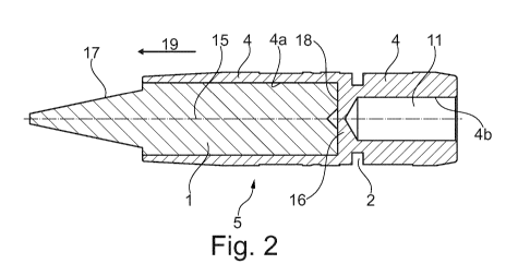
The invention relates to a projectile (5) with a frangible material for short-trajectory ammunition. In order that there are no great losses of precision and that the internal ballistic loading is not so great as to lead to destruction of the projectile, it is proposed according to the invention that the projectile (5) consists of a brass casing (4), the casing (4) has, seen in the direction of flight, a front cylindrical receiving space (4a) and a rear cylindrical receiving space (4b), the two receiving spaces (4a, 4b) are arranged coaxially in relation to the longitudinal axis (15) of the projectile and are separated from one another by a separating wall (16), the separating wall (16) forms the base (18) of the front receiving space (4a) and a core (1) of a frangible material is inserted in the front receiving space (4a), the core (1) protrudes with its tip (17) out of the front receiving space (4a) and, in the region of the separating wall (16), the casing (4) incorporates at least one predetermined breaking location (2), running around the casing (4).


French Abstract

L'invention concerne un projectile (5) pourvu d'un matériau désintégrant pour une munition courte portée. Afin que les pertes de précision ne soient pas trop importantes et que la sollicitation balistique interne ne soit pas à un niveau tel que le projectile est abîmé, selon l'invention, le projectile (5) est formé d'une enveloppe (4) en laiton, l'enveloppe (4), vue dans le sens de la trajectoire, présente un espace de réception (4a) cylindrique avant et un espace de réception (4b) cylindrique arrière, les deux espaces de réception (4a, 4b) sont disposés de manière coaxiale par rapport à l'axe (15) longitudinal du projectile et séparés l'un de l'autre par une paroi de séparation (16), la paroi de séparation (16) forme le fond (18) de l'espace de réception (4a) avant et un noyau (1) en matériau désintégrant est disposé dans l'espace de réception (4a) avant, le noyau (1) fait saillie avec sa pointe (17) de l'espace de réception (4a) avant et au moins une position de rupture (2) est réalisée dans l'enveloppe (4), tout autour de l'enveloppe (4), au niveau de la paroi de séparation (16).

Claims

Note: Claims are shown in the official language in which they were submitted.


- 6 -
CLAIMS
1. A projectile with a frangible material for short-range ammunition, the
projectile extending
along a longitudinal axis and comprising a shell made of brass and having a
circumference,
an outer surface and front and rear ends, the shell, when seen in a direction
of flight,
comprises a front cylindrical receiving space and a rear cylindrical receiving
space, the
front and rear receiving spaces being arranged coaxially with the longitudinal
axis and
being separated from each other by a partition, wherein the partition forms a
floor of the
front receiving space, wherein a core made of the frangible material is
inserted into the
front receiving space, a tip of the core protruding out of the front receiving
space, and
wherein at least one predetermined breaking point, running around the
circumference of
the shell, is formed in the shell in a region of the partition.
2. The projectile according to claim 1, wherein a tracer composition is
arranged in the rear
receiving space.
3. The projectile according to claim 1 or 2, wherein the core is glued or
pressed into the front
receiving space.
4. The projectile according to any one of claims 1 to 3, wherein the core
comprises bevels
or grooves running parallel to the longitudinal axis on the outer surface of
the shell from
the rear end to the front end of the shell.
5. The projectile according to any one of claims 1 to 4, wherein a bore
hole that connects the
front receiving space to the rear receiving space is in the partition wall.
6. The projectile according to any one of claims 1 to 5, wherein a blind
bore is within the
partition wall and has a connection to the front receiving space.
7. The projectile according to any one of claims 1 to 6, comprising two
predetermined
breaking points running around the circumference of the shell in the region of
the partition
wall and wherein one of the two predetermined breaking point is formed in a
rear end of
the partition wall as seen in the direction of flight.

- 7 -
8. The projectile according to any one of claims 1 to 6, wherein the
predetermined breaking
point is formed at right angles to the longitudinal axis and is V-shaped or U-
shaped in
cross-section.
9. The projectile according to any one of claims 1 to 8, wherein the inner
wall of the front
receiving space comprises one or more notches which are parallel to the
projectile axis or
run in a spiral.
10. The projectile according to claim 7, wherein the two predetermined
breaking points are
formed at right angles to the longitudinal axis and are V-shaped or U-shaped
in cross-
section.

Description

Note: Descriptions are shown in the official language in which they were submitted.


- 1 -
PROJECTILE WITH REDUCED RICOCHET RISK
Field
The invention relates to a projectile which is partly made of a frangible
material, for short-range
ammunition.
Background
Short-range ammunition has the purpose of enabling the use of larger calibers
in smaller training
areas. A greater drop in speed is generated by structural measures. This can
be realized with a
low projectile weight. A further option is a modification of the external
projectile geometry. There
are various basic principles in this case, such as a reduction of the twist-
stabilization (GD)
resulting from an aerodynamically unfavorable front or rear end, or a desired
pressure reduction
over the firing process, thereby reducing the acceleration of the projectile.
Frangibility is a property of special projectiles and means that the
projectile material is designed
so that the projectiles fragment into small particles upon impacting hard
targets. In German,
frangible is translated as "zerbrechbar." The English term, however, is also
commonly used in the
German language.
Frangible ammunition already exists in an enormous variety. In particular,
projectiles with a
polymer matrix or with a metal matrix are known. The purpose in this case is
the crumbling of the
projectile into the smallest possible particles upon impact with a hard
surface. The particles have
low sectional density. The result is a minimal potential hazard for nearby
objects. However,
frangible projectiles are relatively difficult to use. For larger calibers,
the radial force arising from
the spin can result in the projectile bursting in the air.
Figure 1 shows a cartridge with a frangible projectile according to the prior
art. The frangible
projectile is inserted into a casing, wherein the ogive of the projectile
protrudes from the casing.
After the frangible projectile impacts, by way of example, a steel plate, the
frangible projectile
breaks apart into dust.
The following problems occur with short-range projectiles:
- Short-range projectiles can have significant losses of precision due to the
modified geometry.
CA 2970505 2019-12-30

-2-
- Light short-range projectiles demonstrate a problematic reloading
behavior, since a
consistent recoil is required for the reloading movement.
- If a short-range ricochet occurs, there is a considerable danger for the
shooter and for third
parties.
- Degradation on the rotor blade or propellers of aircraft and helicopters due
to plastic caps
discharging.
- Purely frangible projectiles have the problem, in the case of large
ammunition types, that
the internal ballistic load is so great that it leads to the destruction of
the projectile.
Summary
The problem addressed by the invention is that of providing a projectile in
such a manner that the
aforementioned disadvantages are avoided. According to a broad aspect, there
is provided a
projectile with a frangible material for short-range ammunition, the
projectile extending along a
longitudinal axis and comprising a shell made of brass and having a
circumference, an outer
surface and front and rear ends, the shell, when seen in a direction of
flight, comprises a front
cylindrical receiving space and a rear cylindrical receiving space, the front
and rear receiving
spaces being arranged coaxially with the longitudinal axis and being separated
from each other
by a partition, wherein the partition forms a floor of the front receiving
space, wherein a core made
of the frangible material is inserted into the front receiving space, a tip of
the core protruding out
of the front receiving space, and wherein at least one predetermined breaking
point, running
around the circumference of the shell, is formed in the shell in a region of
the partition. Due to the
modified geometry there is no loss of precision and the internal ballistic
load is not so great that it
leads to the destruction of the projectile. In addition, a groove or spiral
formed in the front space
can have further predetermined breaking points.
In an advantageous embodiment according to the invention, a tracer composition
is arranged in
the rear receiving space. The rear receiving space lends itself to this, and
the tracer composition
even desirably shifts the center of gravity slightly toward the rear, thereby
improving the flight path.
The core is preferably glued or pressed into the front receiving space. Both
are appropriate fixing
methods which lead to the desired anchorages.
CA 2970505 2019-12-30

- 3 -
To direct compressed air away, in particular in the case of press-fitted
cores, in an advantageous
embodiment the core has bevels or grooves on its outer surface running from
the rear end up to
the front end of the shell, parallel to the projectile longitudinal axis. In
another embodiment, a bore
hole is arranged in the partition wall, connecting the front receiving space
to the rear receiving
space. This also directs the compressed air away.
A blind hole with a connection to the front receiving space can also be
constructed in the partition
wall. This blind hole also functions to reduce pressure.
In a specific embodiment, two circumferential predetermined breaking points
running around the
circumference of the shell are formed in the shell in the region of the
partition, wherein one
predetermined breaking point is formed in the rear end of the partition wall,
as seen in the direction
of flight. The predetermined breaking points are preferably formed at a right
angle to the projectile
longitudinal axis and are constructed with a V-shaped or U-shaped cross-
section. These
predetermined breaking points improve the segmentation behavior.
In a specific embodiment, the inner wall of the front receiving space has one
or more notches
which are parallel to the projectile axis or run in a spiral. This improves
the anchoring of the
frangible core in the front receiving space.
Brief description of the figures
The invention is explained in greater detail below with reference to four
figures.
Figure 1 shows a shell according to the prior art.
Figure 2 shows an embodiment of a projectile according to the invention.
Figure 3 shows an impact of an embodiment of the projectile against a hard
target.
Figure 4 shows an impact of another embodiment of the projectile against a
hard target.
Detailed description of embodiments
Variants, examples and preferred embodiments of the invention are described
hereinbelow.
Referring to the figures, a shell 4 has, seen in the direction of flight 19, a
front 4a and a rear
cylindrical receiving space 4b in the projectile tail 11. The front receiving
space 4a was inserted
CA 2970505 2019-12-30

- 4 -
from the front, and the rear receiving space 4b was inserted from the rear, of
the shell 4. Both
receiving spaces 4a, 4b are arranged coaxially with the projectile
longitudinal axis 15 of the
projectile and are separated from each other by a partition wall 16. The
partition wall 16 forms the
floor of the receiving space 4a. The frangible core is inserted into the front
receiving space 4a,
preferably via a press fit. The front tip 17 of the frangible core 1 projects
out of the front receiving
space 4a and/or the shell 4. A tracer composition (not shown in the figure) is
inserted in one
embodiment of the invention in the rear receiving space 4b. A predetermined
breaking point 2
running around the circumference of the shell 4 is formed in the shell 4
adjoining the partition wall
16. This predetermined breaking point 2 is formed at a right angle to the
projectile longitudinal
axis 15, and can be constructed with a rectangular cross-section, as shown.
However, a V-shaped
predetermined breaking point 2 is preferred, as shown in Fig 4.
The external geometry of the projectile, consisting therefore of a frangible
core 1 and a shell 4,
largely corresponds to a known and proven short-range projectile of the
applicant. This meets
requirements in terms of precision, loading safety, and trajectory. The risk
to the surroundings is
reduced by two systems. On the one hand, a core 1 which is made of frangible
material is inserted
into the shell 4 from the front, as seen in the shooting direction. A
"frangible core" means a core
which breaks apart¨for example, to dust¨upon impact with a hard target. On the
other hand,
predetermined breaking points 2 are introduced into the projectile tail 11 so
that the residual mass
of the individual parts corresponds at most to the mass of a conventional
small-caliber projectile.
The shell 4 of the projectile is preferably made of brass. With brass as the
shell, the projectile
according to the invention has largely broken apart to dust upon impact. This
was surprising for a
person skilled in the art, and not predicted. Upon the impact of the
projectile 5 against a hard
target 17 (see Figure 3), the frangible core 1 is pressed into the shell 4.
During this pressing, the
frangible core 1 abruptly produces a high hydrostatic pressure (see arrows 20
in Figure 3). This
causes a splintering of the majority of the projectile. The brass of the shell
4 naturally
demonstrates a brittle behavior over such a short stress period. The
multiaxial stress state when
the frangible core 1 bursts also supports the brittle behavior of the brass of
the shell 4. In this way,
the impact energy is reduced to an extreme degree, and nearly negated. The
rest of the projectile
then breaks apart into lighter parts due to the defined predetermined breaking
point 2. These
individual parts have very low sectional density due to their geometry. This
significantly decreases
the risk to the surroundings. In a particularly advantageous solution, the
frangible core 1 of the
CA 2970505 2019-12-30

- 5 -
projectile is a sub-caliber projectile which is simply inserted into the front
receiving space 4a. The
attachment between the shell 4 and the frangible core 1 can be realized by
means of adhesive or
a press fit. If a press fit is selected, lateral bevels on the core can direct
the compressed air away.
A further possibility is that the compressed air is directed away, when the
projectile is assembled,
by a bore hole in the projectile longitudinal axis 15 through the partition
16, or by a blind bore in
the partition wall, so that the pressure can be minimized. The projectile tail
11 is also made of
brass, since brass is suitable for press-fitting tracer compositions.
Figure 4 shows another embodiment of a projectile 5 according to the
invention, consisting of a
shell 4 made of brass and a frangible core 1. The shell 4 has in this case as
well, seen in the
direction of flight 19, a front 4a and a rear cylindrical receiving space 4b
in the projectile tail 11.
The front receiving space 4a was inserted from the front, and the rear
receiving space 4b was
inserted from the rear, of the shell 4. Both receiving spaces 4a, 4b are
arranged coaxially with the
projectile longitudinal axis 15 of the projectile and are separated from each
other by a partition
wall 16. The partition wall 16 in this embodiment is substantially thicker
than in the embodiment
of Fig 2. The partition wall 16 in this case also forms the floor of the
receiving space 4a. The
frangible core 1 is inserted into the front receiving space 4a, preferably via
a press fit. The front
tip 17 of the frangible core 1 projects in this case as well out of the front
receiving space 4a and/or
the shell 4. A tracer composition (not shown in the figure) can be inserted in
the rear receiving
space 4b. A predetermined breaking point 2a running around the circumference
of the shell 4 is
formed on the shell 4 adjoining the rear segment¨seen in the shooting
direction¨of the partition
wall 16. In the embodiment shown here¨also seen in the shooting direction¨a
predetermined
breaking point 2b is also formed on the front segment of the partition wall
16. These
predetermined breaking points 2a, 2b are formed at a right angle to the
projectile longitudinal axis
15 and are V-shaped in cross-section.
CA 2970505 2019-12-30

Representative Drawing
A single figure which represents the drawing illustrating the invention.
Administrative Status

For a clearer understanding of the status of the application/patent presented on this page, the site Disclaimer , as well as the definitions for Patent , Administrative Status , Maintenance Fee  and Payment History  should be consulted.

Administrative Status

Title Date
Forecasted Issue Date 2020-08-18
(86) PCT Filing Date 2015-12-10
(87) PCT Publication Date 2016-06-16
(85) National Entry 2017-06-09
Examination Requested 2019-03-04
(45) Issued 2020-08-18

Abandonment History

There is no abandonment history.

Maintenance Fee

Last Payment of $210.51 was received on 2023-11-28


 Upcoming maintenance fee amounts

Description Date Amount
Next Payment if standard fee 2024-12-10 $277.00
Next Payment if small entity fee 2024-12-10 $100.00

Note : If the full payment has not been received on or before the date indicated, a further fee may be required which may be one of the following

  • the reinstatement fee;
  • the late payment fee; or
  • additional fee to reverse deemed expiry.

Patent fees are adjusted on the 1st of January every year. The amounts above are the current amounts if received by December 31 of the current year.
Please refer to the CIPO Patent Fees web page to see all current fee amounts.

Payment History

Fee Type Anniversary Year Due Date Amount Paid Paid Date
Application Fee $400.00 2017-06-09
Maintenance Fee - Application - New Act 2 2017-12-11 $100.00 2017-11-23
Maintenance Fee - Application - New Act 3 2018-12-10 $100.00 2018-12-07
Request for Examination $800.00 2019-03-04
Maintenance Fee - Application - New Act 4 2019-12-10 $100.00 2019-12-10
Final Fee 2020-06-18 $300.00 2020-06-04
Maintenance Fee - Patent - New Act 5 2020-12-10 $204.00 2021-05-03
Late Fee for failure to pay new-style Patent Maintenance Fee 2021-05-03 $150.00 2021-05-03
Maintenance Fee - Patent - New Act 6 2021-12-10 $204.00 2021-12-30
Late Fee for failure to pay new-style Patent Maintenance Fee 2021-12-30 $150.00 2021-12-30
Maintenance Fee - Patent - New Act 7 2022-12-12 $203.59 2022-12-28
Late Fee for failure to pay new-style Patent Maintenance Fee 2022-12-28 $150.00 2022-12-28
Maintenance Fee - Patent - New Act 8 2023-12-11 $210.51 2023-11-28
Owners on Record

Note: Records showing the ownership history in alphabetical order.

Current Owners on Record
RUAG AMMOTEC AG
Past Owners on Record
None
Past Owners that do not appear in the "Owners on Record" listing will appear in other documentation within the application.
Documents

To view selected files, please enter reCAPTCHA code :


To view images, click a link in the Document Description column. To download the documents, select one or more checkboxes in the first column and then click the "Download Selected in PDF format (Zip Archive)" or the "Download Selected as Single PDF" button.

List of published and non-published patent-specific documents on the CPD .

If you have any difficulty accessing content, you can call the Client Service Centre at 1-866-997-1936 or send them an e-mail at CIPO Client Service Centre.


Document
Description 
Date
(yyyy-mm-dd) 
Number of pages   Size of Image (KB) 
Amendment 2019-12-30 14 541
Description 2019-12-30 5 244
Claims 2019-12-30 2 54
Drawings 2019-12-30 2 57
Final Fee 2020-06-04 4 101
Cover Page 2020-07-27 1 43
Representative Drawing 2017-06-09 1 20
Representative Drawing 2020-07-27 1 6
Abstract 2017-06-09 2 101
Claims 2017-06-09 2 53
Drawings 2017-06-09 2 62
Description 2017-06-09 5 231
Representative Drawing 2017-06-09 1 20
National Entry Request 2017-06-09 5 128
International Search Report 2017-06-09 17 586
Cover Page 2017-08-18 1 58
Request for Examination 2019-03-04 2 62
Examiner Requisition 2019-07-05 3 201