Note: Descriptions are shown in the official language in which they were submitted.
DESCRIPTION
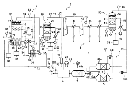
EXHAUST GAS PROCESSING SYSTEM AND PROCESSING METHOD
Technical Field
[0001]
The present invention relates to an exhaust gas
processing system and a processing method for removing a
sulfur oxide, a nitrogen oxide and the like from an
exhaust gas containing carbon dioxide, such as combustion
gas, to separate and recover carbon dioxide.
Background Art
[0002]
In thermal power stations, ironworks, boilers and
other facilities, fuels such as coal, heavy oil and extra
heavy oil are used in a large quantity. Sulfur oxides,
nitrogen oxides, and carbon dioxide discharged by the
burning of the fuels need quantitative and concentration
limitations with respect to the release thereof from the
viewpoint of prevention of air pollution and conservation
of global environment. In recent years, carbon dioxide
has been regarded as a problem as it is the main cause of
global warming, so that a movement of suppressing the
emissions thereof in the world has been becoming activated.
Thus, various researches have been actively promoted for
making it possible to recover and store carbon dioxide
from combustion exhaust gas or process exhaust gas without
discharging carbon dioxide into the atmosphere.
Combustion exhaust gas contains not only carbon dioxide
and water but also nitrogen oxides, sulfur oxides, mercury,
hydrogen chloride, ash dusts (particulate matters) and the
like as minor components. It is therefore important from
the viewpoint of environmental conservation to decrease
the quantity of impurities contained in the carbon dioxide
recovered from the exhaust gas to increase the purity of
carbon dioxide.
1
CA 2971059 2017-06-16
[0003]
Of the nitrogen oxides contained in combustion
exhaust gas, nitrogen dioxide is removable by a wet
absorption processing using an alkaline agent. However,
nitrogen monoxide is poorly soluble in water. Thus, many
of ordinarily performed denitration techniques are based
on a dry-type ammonia catalytic reduction method, and
nitrogen oxides are reduced by catalytic reaction by
supplying ammonia or some other hydrogen source. When a
desulfurization and denitration apparatus is formed on the
basis of such a technique, in its desulfurization unit,
sulfur oxides in an exhaust gas are processed in the state
of ammonium salts.
[0004]
In the meantime, about the desulfurization methods,
various wet or dry processing techniques have been
researched for removing sulfur oxides, using an alkaline
desulfurizing agent. For example, Patent Literature 1
listed below describes an exhaust gas wet processing
method of bringing the exhaust gas and slurry containing a
desulfurizing agent into liquid-gas contact with each
other, in which carbon dioxide is recovered by
desulfurization of the exhaust gas. Examples of the
alkaline agent usable in such a desulfurization method
include sodium hydroxide (or sodium carbonate), limestone
(or slaked lime or dolomite), and magnesium hydroxide.
Although sodium hydroxide is very high in efficiency of
removing the sulfur oxides, it is expensive to increase
costs for the processing. It is therefore general to
apply, to large-sized plants such as thermal power
stations, a limestone/gypsum method, in which limestone
(calcium carbonate) or slaked lime (calcium hydroxide),
which is inexpensive, is used.
[0005]
As a method in which a hydrogen source or a
desulfurizing agent as described above is not used,
2
CA 2971059 2017-06-16
suggested is a method of pressurizing the exhaust gas, and
then cooling it to condense the water content in the
exhaust gas (see Patent Literature 2 listed below). In
this method, sulfur oxides and nitrogen oxides contained
in the pressurized exhaust gas are dissolved in the
condensed water, and denitration and desulfurization of
the exhaust gas are performed by separating the condensed
water from the exhaust gas.
Citation List
Patent Literatures
[0006]
Patent Literature 1: JP 2012-106163 A
Patent Literature 2: WO 2012/107953 A
Summary of Invention
Technical Problem
[0007]
In the technique of Patent Literature 2, by
pressurizing and cooling an exhaust gas, sulfur oxides and
nitrogen oxides are removed together with condensed water.
Thus this technique does not require any chemical agent
such as the desulfurizing agent, etc. However, acids
(sulfuric acid and sulfurous acid) generated from the
sulfur oxides easily damage the compressor and other
equipment. Accordingly, if this technique is used singly
to attain desulfurization and denitration, a large burden
is imposed onto the apparatus to cause a problem about
costs for maintaining the facilities. It is also
difficult to attain the desulfurization and the
denitration with a high removing efficiency. In the
meantime, about denitration methods, a reduction method in
which a hydrogen source such as ammonia is used makes
difficult the reduction in the processing cost. Thus it
is desired that the nitrogen oxides can be processed
without using such a resource. In connection with this
3
CA 2971059 2017-06-16
point, since the desulfurization method according to the
limestone/gypsum method makes use of relatively
inexpensive limestone as an absorbent, it is an
advantageous desulfurization method for processing costs
and is thus favorable for economy.
[0008]
In order to spread the processing of exhaust gas,
economy is important. To increase the economic efficiency
in the whole of an exhaust gas processing process, it is
important to increase the economic efficiency in each of
the processing techniques performed in the processing
process. After being subjected to desulfurization and
denitration, the exhaust gas contains carbon dioxide as a
main component and carbon dioxide is stored in the ground
under the present circumstances. However, if an effective
use of recovered carbon dioxide is realized, it increases
the economic efficiency. Carbon dioxide recovered from
the desulfurized and denitrated exhaust gas contains argon,
oxygen, nitrogen and the like in a small proportion. If
carbon dioxide of high purity can be efficiently recovered,
it can be supplied to the market as liquefied carbon
dioxide or such a product, to result in industrial
usefulness. At this time, in order that such a technique
becomes advantageous economically, the recovery efficiency
of the carbon dioxide of high purity is important.
[0009]
In a desulfurization method according to the
limestone/gypsum method, when a slurry in which an
absorbent is dispersed in water is used as an absorbing
liquid to capture sulfur oxides in the exhaust gas, the
absorbing liquid is deprived of water content if the
slurry contacts the exhaust gas with a high temperature
that is introduced from a combustion system, so that fine
solid particles are scattered and entrained in the exhaust
gas easily. Such scattered particles easily cause a
failure of wear and breakdown in the subsequent machinery.
4
CA 2971059 2017-06-16
If a filtrating member such as a filter bag or the like is
used to separate the scattered particles from the exhaust
gas, ventilation resistance of the exhaust gas becomes
very large so that energy and power device becomes
necessary for urging the gas flow. Accordingly, when the
desulfurization method according to the limestone/gypsum-
method is used in the exhaust gas processing process, it
is also important to devise so as to address the problem
of scattered particles as described above.
[0010]
An object of the present invention is to solve the
above-mentioned problems and provide an exhaust gas
processing system and a processing method that are
excellent in economic efficiency and that are capable of
efficiently recovering carbon dioxide with high purity,
with use of desulfurization technique according to the
limestone/gypsum method.
Another object of the invention is to provide an
exhaust gas processing system and a processing method with
less damage and troubles of the equipment when processing
the exhaust gas, which enable to attain the
desulfurization and denitration of the exhaust gas
efficiently to recover carbon dioxide with high purity and
which make possible to decrease the energy necessary for
the processing.
[0011]
Still another object of the invention is to provide
an exhaust gas processing system and a processing method
that installation conditions and installation environment
are not restricted, that operating costs can be decreased,
and that maintenance and management are easy.
Technical Solution
[0012]
In order to solve the above-mentioned problems, the
inventors have conducted eager researches to find out that,
CA 2971059 2017-06-16
using the construction of the desulfurization method
according to the limestone/gypsum method, efficient
recovering of carbon dioxide with high purity is possible,
and then achieved the present invention. At this time,
the problem of scattered particles in the limestone/gypsum
method can be solved by a simple configuration, and it has
also achieved to effectively implement the processing of
the exhaust gas while using energy efficiently in
combination with the configuration according to the
pressurization and cooling.
[0013]
According to an aspect of the present invention, an
exhaust gas processing system comprises: a desulfurization
unit that removes a sulfur oxide from an exhaust gas
according to the limestone/gypsum method; a denitration
unit arranged in a subsequent stage of the desulfurization
unit to remove a nitrogen oxide from the exhaust gas; a
carbon dioxide recovery unit arranged at a subsequent
stage of the denitration unit to recover carbon dioxide
from the exhaust gas; and an oxygen supply unit that
supplies a fraction of a post-recovery gas discharged from
the carbon dioxide recovery unit as an oxygen source to
the desulfurization unit.
[0014]
Moreover, according to an aspect of the present
invention, an exhaust gas processing method comprises: a
desulfurization processing to remove a sulfur oxide from
an exhaust gas according to the limestone/gypsum method; a
denitration processing to remove a nitrogen oxide from the
exhaust gas; a carbon dioxide recovery processing to
recover carbon dioxide from the exhaust gas; and an oxygen
supply processing to supply a fraction of a post-recovery
gas discharged by the carbon dioxide recovery processing,
to the desulfurization processing as an oxygen source.
[0015]
In the exhaust gas processing system, the oxygen
6
CA 2971059 2017-06-16
supply unit may include: a monitor having an analyzer for
monitoring the purity and the recovery ratio of the
recovered carbon dioxide recovered by the carbon dioxide
recovery unit; and an adjusting apparatus that adjusts the
proportion of the post-recovery gas to be supplied to the
desulfurization unit of the post-recovery gas discharged
from the carbon dioxide recovery unit, based on the purity
and the recovery ratio of the recovered carbon dioxide
that are monitored by the monitor. The adjusting
apparatus may be set to compare the purity of the
recovered carbon dioxide and the recovery ratio of the
carbon dioxide that are monitored by the monitor, with a
target purity and a target recovery ratio, and to perform
at least one of an adjustment to decrease the proportion
of the post-recovery gas to be supplied to the
desulfurization unit when the monitored purity of the
recovered carbon dioxide is lower than the target purity,
and an adjustment to increase the proportion of the post-
recovery gas to be supplied to the desulfurization unit
when the monitored recovery ratio of the recovered carbon
dioxide is lower than the target recovery ratio.
[0016]
Moreover, the monitor may further include an
analyzer for monitoring the concentration of sulfur
dioxide in the exhaust gas discharged from the
desulfurization unit, and the adjusting apparatus may be
configured to compare the sulfur dioxide concentration in
the exhaust gas that is monitored by the monitor, with a
target sulfur dioxide concentration, and to perform an
adjustment to increase the proportion of the post-recovery
gas to be supplied to the desulfurization unit when the
monitored sulfur dioxide concentration in the exhaust gas
is higher than the target sulfur dioxide concentration.
Further, the oxygen supply unit may include a separator
for separating carbon dioxide from the post-recovery gas
discharged from the carbon dioxide recovery unit, and a
7
CA 2971059 2017-06-16
carbon dioxide supply unit that supplies the carbon
dioxide separated by the separator to the denitration unit,
and the oxygen supply unit is allowed to supply a fraction
of the post-recovery gas from which the carbon dioxide has
been separated by the separator to the desulfurization
unit.
[0017]
In the above-mentioned structure, the
desulfurization unit may include a desulfurizer that
removes the sulfur oxide from the exhaust gas with use of
an absorbing liquid containing a calcium compound, and a
washing apparatus that wash the exhaust gas discharged
from the desulfurizer with use of washing water, thereby
removing calcium-containing particles contained in the
exhaust gas, and the oxygen supply unit is allowed to
supply a fraction of the post-recovery gas to the
absorbing liquid in the desulfurizer. In accordance with
the above, it is possible to overcome the problem of
scattered particles in the desulfurizer.
[0018]
The denitration unit may include a reactor that
advances an oxidation reaction to produce nitrogen dioxide
from nitrogen monoxide, and a denitration apparatus that
removes nitrogen dioxide from the exhaust gas with use of
an aqueous absorbing liquid. In one embodiment thereof,
such a configuration is possible that the reactor may
include at least one compressor for compressing the
exhaust gas discharged from the desulfurization unit, and
that the denitration unit may further include at least one
cooler for cooling the exhaust gas pressurized by the at
least one compressor. In another embodiment thereof, such
a configuration is possible that the desulfurization unit
may further include a first reactor arranged in a
preceding stage of the desulfurizer and advancing an
oxidation reaction to produce sulfur trioxide from sulfur
dioxide, and the denitration unit may include a second
8
CA 2971059 2017-06-16
reactor arranged in a subsequent stage of the
desulfurization unit and advancing an oxidation reaction
to produce nitrogen dioxide from nitrogen monoxide, and a
denitration apparatus that remove nitrogen dioxide from
the exhaust gas with use of an aqueous absorbing liquid.
[0019]
The exhaust gas processing system may be configured
to further include a drying unit that removes water from
the exhaust gas, and a mercury removing unit that removes
mercury form the exhaust gas, so that carbon dioxide with
high purity can be efficiently recovered.
Advantageous Effects of Invention
[0020]
According to the present invention, previous cooling
of the exhaust gas is unnecessary and efficient recovery
of high purity carbon dioxide is possible with use of the
configuration of a desulfurization processing according to
the a limestone/gypsum method. Thus it is advantageous in
development of the use of the recovered carbon dioxide.
Moreover, since the problem of scattered particles in the
exhaust gas processing can be eliminated by a simple
technique, it contributes to a decrease in operating costs
for the exhaust gas processing to improve economic
efficiency. Installation conditions, etc. of the system
are not unnecessarily limited, and it is possible to
perform efficiently the desulfurization and the
denitration of an exhaust gas without increasing of the
processing costs. Accordingly, it contributes to
installation of the processing system and spread of the
processing method, for an exhaust gas containing carbon
dioxide such as oxygen combustion gas and the like, and it
is therefore useful in responding to environmental issues.
Since it can be carried easily by using ordinary
facilities without requiring special equipment or
expensive device, it is economically advantageous.
9
CA 2971059 2017-06-16
Brief Description of the Drawings
[0021]
FIG. 1 is a schematic structural view illustrating
an embodiment of the exhaust gas processing system
according to the present invention.
FIG. 2 is a schematic structural view illustrating
another embodiment of the exhaust gas processing system
according to the present invention.
FIG. 3 is a schematic structural view illustrating
still another embodiment of the exhaust gas processing
system according to the present invention.
Description of Embodiments
[0022]
Main components of combustion gas and the like
exhaust gases are water and carbon dioxide, and they
further contain, as impurities, sulfur oxides, nitrogen
oxides, hydrogen chloride, oxygen, mercury, soot and dust
(particulate matters) and the like in a small proportion,
and also contain inert argon and nitrogen. The amount of
oxygen remaining in exhaust gases is varied in accordance
with the combustion conditions, but the oxygen content may
be approximated at about 5% and it is similar in the
exhaust gases that the above-mentioned impurities are
contained in a small proportion. Accordingly, oxygen and
the like remain in a small proportion in the exhaust gas
after subjected to desulfurization and denitration. Thus,
if carbon dioxide in the exhaust gas is refined and
recovered with high purity, carbon dioxide containing
oxygen, argon and nitrogen in a high concentration is
discharged as the purification residue after the recovery.
In order to increase the recovery efficiency of the carbon
dioxide, it is necessary to decrease the proportion of the
impurities contained in the exhaust gas after subjected to
the desulfurization and denitration. In particular,
CA 2971059 2017-06-16
decrease of the oxygen concentration is important since
the oxygen concentration affects the purification
efficiency in the purification of the carbon dioxide.
[0023]
In the meantime, oxygen is a component usable in the
processing for the desulfurization and the denitration of
the exhaust gas. Firstly, in the desulfurization
processing according to the limestone/gypsum method,
oxygen is usable as an oxidation source for depositing and
separating, as calcium sulfate, sulfite ions produced from
sulfur dioxide in the exhaust gas. Secondly, oxygen is an
element necessary for making it possible to adopt a wet
processing as a method for denitrating the exhaust gas.
The sulfur oxides (S0x) include sulfur dioxide, sulfur
trioxide and the like, and these oxides are each soluble
in water. Meanwhile, the nitrogen oxides (N0x) are mainly
present as nitrogen monoxide or nitrogen dioxide. Since
nitrogen monoxide is insoluble in water, a wet processing
is inapplicable as it is. However, if nitrogen monoxide
is oxidized to nitrogen dioxide, which is water-soluble,
the nitrogen oxides are removable by a wet-type
denitration processing using water.
[0024]
In the present invention, a desulfurization
processing is adopted according to the limestone/gypsum
method, and in the desulfurization processing, a post-
recovery gas discharged as purified residue after the
recovery of carbon dioxide is partially used as an oxygen
source for oxidizing sulfite ions produced from sulfur
dioxide in the exhaust gas. That is, as the firstly-
mentioned oxygen source, oxygen contained in the post-
recovery gas is used. Since the main component of the
post-recovery gas is carbon dioxide, the configuration is
made in such a manner that the post-recovery gas that has
undergone the oxidation of sulfite ions in the absorbing
liquid is allowed to flow again in the processing process,
11
CA 2971059 2017-06-16
thereby recovering the carbon dioxide again. This is
favorable also for the purification efficiency of the
carbon dioxide. The reason why the post-recovery gas is
used not wholly but partially is to avoid extreme increase
in the concentration of argon and nitrogen, which are
impurities other than oxygen, due to enrichment thereof in
the exhaust gas after subjected to the processing for the
desulfurization and the denitration.
[0025]
That is, the exhaust gas processing system according
to the present invention has a desulfurization unit which
removes a sulfur oxide from an exhaust gas according to
the limestone/gypsum method; a denitration unit which
removes a nitrogen oxide from the exhaust gas; a carbon
dioxide recovery unit which recovers carbon dioxide from
the exhaust gas; and an oxygen supply unit which supplies
a fraction of a post-recovery gas discharged from the
carbon dioxide recovery unit, as an oxygen source, into
the desulfurization unit. The denitration unit is
arranged in a subsequent stage of the desulfurization unit,
and the carbon dioxide recovery unit is arranged in a
subsequent stage of the denitration unit. The
desulfurization unit according to the limestone/gypsum
method has a desulfurizer in which an absorbing liquid
containing a calcium compound is used to remove the sulfur
oxide from the exhaust gas. Oxygen contained in the post-
recovery gas is supplied to the absorbing liquid in the
desulfurizer, and sulfite ions generated from the absorbed
sulfur oxides are oxidized to calcium sulfate. The main
component of the post-recovery gas in which oxygen has
been consumed is carbon dioxide, so that the carbon
dioxide concentration in the exhaust gas to be supplied to
the carbon dioxide recovery unit increases. Thus, the
efficiency is improved in recovery of high-concentration
carbon dioxide by purification.
[0026]
12
CA 2971059 2017-06-16
The desulfurization processing according to the
limestone/gypsum method has a problem that scattered
particles generated at the time of contacting the exhaust
gas with a high temperature cause a failure to subsequent
equipment. In order to solve this problem, the system for
processing the exhaust gas is configured by interposing
between its components a washing apparatus which washes
the scattered particles with water to remove. The washing
apparatus has a simple structure and it makes possible to
collect the scattered particles without increasing the
ventilation resistance of the exhaust gas, so that
consumption of power is possibly suppressed. In this way,
it is possible to prevent a failure caused by the
scattered particles in subsequent equipment. Thus, a
pressurizing device such as a compressor can be arranged
subsequently so as to pressurize the exhaust gas. When
the exhaust gas is pressurized, an oxidation reaction by
which nitrogen monoxide is converted to nitrogen dioxide
is advanced by the oxygen remaining in the exhaust gas.
Thus a wet-type denitration processing using washing water
becomes possible. In regard to the sulfur oxides,
although sulfuric acid arising from water vapor and the
sulfur trioxide produced by the oxidation reaction is
prone to damage the compressor or the like by corroding
the metal, the corrosion by sulfuric acid is avoidable
even when the pressurizing device is used since the
exhaust gas is previously subjected to the desulfurization
processing. Accordingly, it is possible to remove
nitrogen oxides economically in combination of the
oxidation of nitrogen monoxide by using the progress of
the oxidation reaction through the pressurization, and the
wet-type denitration processing. This is very
advantageous as compared with the case of applying a
denitration processing according to the reduction method.
As a result, the desulfurization and the denitration can
be inexpensively and safely attained by subjecting the
13
CA 2971059 2017-06-16
exhaust gas to the desulfurization processing according to
the limestone/gypsum method, the oxidation reaction with
pressurization, and the wet-type denitration processing.
This configuration also makes it possible to use oxygen in
the post-recovery gas as the secondly-mentioned oxidizing
source, that is, the oxidizing source for the oxidation
reaction through pressurization.
Hereinafter, embodiments of the exhaust gas
processing system of the present invention will be
described with reference to the attached drawings. In the
drawings, any line represented by a broken line indicates
an electric connection.
[0027]
FIG. 1 illustrates the first embodiment of the
exhaust gas processing system according to the present
invention. A processing system 1 has a desulfurization
unit 2 which removes a sulfur oxide from exhaust gas G, a
denitration unit 3 arranged in a subsequent stage of the
desulfurization unit 2 to remove nitrogen oxides from
exhaust gas G, and a carbon dioxide recovery unit 4
arranged in a subsequent stage of the desulfurization unit
2 and the denitration unit 3 to recover carbon dioxide
from the exhaust gas G. Furthermore, the processing
system 1 has a drying unit 5 which removes water content
from the exhaust gas, and a mercury removing unit 6 which
removes mercury from the exhaust gas, between the
denitration unit 3 and the carbon dioxide recovery unit 4.
[0028]
The desulfurization unit 2 is composed of a
desulfurizer 10 which removes a sulfur oxide from exhaust
gas G with use of absorbing liquid Al, and a washing
apparatus 20 which washing the exhaust gas discharged from
the desulfurizer 10 with use of washing water W. The
desulfurizer 10 is a device that performs a
desulfurization processing according to the
limestone/gypsum method, and that uses, as absorbing
14
CA 2971059 2017-06-16
liquid Al, an aqueous dispersion liquid containing a
calcium compound such as limestone and the like as
alkaline absorbents for absorbing the sulfur oxide. The
desulfurizer 10 has therein a spraying device which sprays
the absorbing liquid Al in the form of droplets in the
exhaust gas G. Specifically, a spray nozzle 11 for
spraying the absorbing liquid Al is provided on the upper
part of the inside of the desulfurizer 10, and a
circulating path 12 is provided on the outside of the
desulfurizer 10 to connect the bottom and the upper part
thereof with each other. Absorbing liquid Al sprayed from
the spray nozzle 11 and stored on the bottom of the
desulfurizer 10 is recirculated to the spray nozzle 11 by
the driving of a pump 13 on the circulating path 12, and
the absorbing liquid Al is repeatedly sprayed. Exhaust
gas G is introduced from a gas inlet portion 14 below the
spray nozzle 11, and a gas-liquid contact phase that
brings the exhaust gas G into contact with absorbing
liquid Al is produced by the spray of absorbing liquid Al
between the spray nozzle 11 and the gas inlet portion 14.
An analyzer S1 is provided in order to measure the
nitrogen oxide concentration and the sulfur dioxide
concentration in the exhaust gas G to be introduced into
the desulfurizer 10. By the contact between the exhaust
gas G and the absorbing liquid Al, the sulfur oxides
contained in the exhaust gas G are absorbed into the
absorbing liquid Al to produce calcium salts. At this
time, sulfur dioxide is dissolved as sulfite ions in the
absorbing liquid Al. In the meantime, sulfur trioxide is
absorbed into absorbing liquid Al and then makes gypsum
(calcium sulfate) which is dispersed and precipitated.
Hydrogen chloride and other acidic halides contained in
the exhaust gas G are also absorbed into absorbing liquid
Al. Furthermore, an advantage of washing and removing
soot and dust is also obtained. The arrangement of the
gas inlet portion 14 may be changed so as to blow the
CA 2971059 2017-06-16
exhaust gas G into absorbing liquid Al stored in the
bottom part. A water-cooling type cooler 15 is provided
on the circulating path 12, and the absorbing liquid Al in
the desulfurizer 10 is cooled through the cooler 15 while
it is circulated in the circulating path 12, thereby
increase of the liquid temperature is prevented.
Furthermore, an inlet portion 71 is provided for supplying
a fraction of post-recovery gas G' discharged from the
carbon dioxide recovery unit 4 to the absorbing liquid Al
in the bottom part of the desulfurizer 10, and a branch
pipe 72 is connected to the inlet portion 71, wherein the
pipe 72 is branched from a pipe 66 (details thereof will
be described later) through which the post-recovery gas G'
is discharged. Flow rate adjusting valves 73 and 74 for
adjusting gas flow rate are fitted to the pipe 66 and the
branch pipe 72, respectively, and, by adjusting these
opening, the flow rate adjusting valves 73 and 74 function
as an adjustment device for adjusting the distribution
ratio of the fraction of post-recovery gas G' to be
supplied to the desulfurization unit in the post-recovery
gas G' discharged from the carbon dioxide recovery unit 4.
Oxygen contained in the post-recovery gas G' oxidizes
sulfite ions dissolved in the absorbing liquid Al to
sulfate ions, so that the sulfur oxides are deposited as
calcium sulfate. The post-recovery gas G' from which
oxygen has been consumed, being composed mainly of carbon
dioxide, emerges out of the absorbing liquid Al to be
contained in the exhaust gas G from which the sulfur
oxides have been removed.
[0029]
The exhaust gas G is cooled by the sprayed absorbing
liquid Al. If the introduced exhaust gas G is high in
temperature, water in the sprayed absorbing liquid is
vaporized by a rise in the temperature of the liquid, so
that components contained in the absorbing liquid turn to
fine solid particles (mist) and they are scattered and
16
CA 2971059 2017-06-16
entrained in the exhaust gas G. The components of the
scattered particles are calcium-containing solids such as
limestone, gypsum, and calcium sulfite. In order to
suppress these solid particles to some extent from being
discharged to the outside with the entrainment in the
exhaust gas G, a mist removing member 16 is arranged above
the spray nozzle 11, and the exhaust gas G passing through
the gas-liquid contact phase to rise up passes through the
mist removing member 16 before discharged from the
desulfurizer 10. The mist removing member 16 comprises a
horizontal layer of a plurality of oblique plates arranged
in parallel to each other with providing gaps between them.
The multiple oblique plates are inclined with respect to
the passage direction (the vertical direction) of the
exhaust gas G, so that the solid particles contained in
the exhaust gas G are easy to collide with the oblique
plates. When the mist removing member 16 is configured to
have a height (the vertical direction) of about 150 to 250
mm and a gap (ventilation width) of about 50 to 100 mm
between the oblique plates, this configuration is
preferred to remove the particles effectively while
suppressing the increase of the ventilation resistance of
the exhaust gas. In order to remove the particles
effectively, it is preferred that the inclined angle of
the oblique plates (with respect to the vertical
direction) is about from about 20 to 45 degrees. If the
colliding solid particles deposit onto the oblique plates,
the mist removing member 16 may be blocked. Thus a
washing nozzle 17 for washing the deposition is located
above the mist removing member 16. The washing nozzle 17
is used in the state that the supply of exhaust gas G and
the desulfurization processing are stopped. The
supernatant of the absorbing liquid Al stored in the
bottom part of the desulfurizer 10 is supplied to the
washing nozzle 17 to wash the mist removing member 16.
[0030]
17
CA 2971059 2017-06-16
A washing apparatus 20 is arranged in a subsequent
stage from the desulfurizer 10, and the exhaust gas G
discharged from the desulfurizer 10 is supplied through a
pipe 18 to the washing apparatus 20. An analyzer S2 is
provided on the pipe 18 to measure the sulfur dioxide
concentration in the exhaust gas G. The washing apparatus
20 is provided in order to remove sufficiently from the
exhaust gas G, scattered particles that cannot be
sufficiently removed by the mist removing member 16 of the
desulfurizer 10, and it is configured as a washing
apparatus for washing the exhaust gas G discharged from
the desulfurizer 10, using washing water W. Thus,
calcium-containing particles contained in the exhaust gas
G are removed. Moreover, hydrogen chloride and soot and
dust contained in the exhaust gas G are also taken into
the washing water. The exhaust gas G is cooled by the
washing.
[0031]
The washing apparatus 20 is configured as follows.
A spray nozzle 21 for spraying washing water W is located
at the inside of the upper part of the washing apparatus
20. A circulating path 22 is located outside the
apparatus to connect the bottom part and the upper part
thereof with each other. For the washing water W, water
is preferably used, and, if an aqueous solution of a
highly water-soluble alkali agent is used as the washing
water W, performance of capturing the scattered particles
(calcium compound) is improved and it also exhibits
desulfurization and denitration effects. A pump 23 is
provided on the circulating path 22, and, by the driving
thereof, washing water W is sprayed from the spray nozzle
21 and stored in the bottom part of the washing apparatus
20. The washing water W is then recirculated to the spray
nozzle 21 through the circulating path 22 to repeat the
spray of washing water W. Below the spray nozzle 21, a
filling material 24 is loaded to promote the contact
18
CA 2971059 2017-06-16
between the exhaust gas G and the washing water W. By
spraying the washing water W from the spray nozzle 21 and
introducing the exhaust gas G from the bottom part of the
washing apparatus 20, the exhaust gas G and the washing
water contact each other in gaps in the filling material
24 so that the scattered particles contained in the
exhaust gas G are captured and washed with the washing
water W. Moreover, washing water W absorbs acidic halides
such as hydrogen chloride, the remaining portion of sulfur
oxides, and nitrogen dioxide each contained in the exhaust
gas G. A water-cooling type cooler 25 is provided on the
circulating path 22 so that the washing water W
circulating in the circulating path 22 is cooled to
prevent a rise in the temperature of washing water W
inside the washing apparatus 20. Thus, the temperature is
kept at an appropriate temperature. Above the spray
nozzle 21, a mist removing member 26 is arranged to
suppress fine droplets or the like of the washing water W
from being entrained in the exhaust gas G and discharged
to the outside. In same manner as the mist removing
member 16 of the desulfurizer 10, the mist removing member
26 may comprise a horizontal layer of a plurality of
oblique plates arranged in parallel to each other with
providing gaps between them. However, the mist removing
member 26 may be in other forms, and it may be configured
with, for example, a net-like member, a porous thin plate
or the like. The exhaust gas G that has passed through
the mist removing member 26 is discharged from the washing
apparatus 20 through a pipe 27. As the washing processing
advances, the calcium compound is incorporated into the
washing water W, and the alkali agent is consumed by
neutralizing the absorbed acidic substances. Accordingly,
a tank 28 is additionally provided to accommodate washing
water of the refill or an alkali agent aqueous solution
having a high concentration. As required, the used
washing water is discharged through the circulating path
19
CA 2971059 2017-06-16
22 from a drain and the fresh washing water or alkali
agent is replenished from the tank 28 through the
circulating path 22 into the washing apparatus 20.
[0032]
Washing water W used in the washing apparatus 20 is
preferably a substantially neutral or basic aqueous
solution having a pH adjusted to about 5 to 9. If an
aqueous solution containing an alkali agent is used as the
washing water W, it is possible to supplement the
desulfurization function of the desulfurizer 10, and the
desulfurization and the removal of the acidic substances
can be performed with a higher precision. The alkali
agent is preferably, for example, an alkali metal
hydroxide such as sodium hydroxide. An analyzer S3 to
measure the pH of washing water W is placed on the bottom
of the washing apparatus 20.
[0033]
In the desulfurizer 10, sulfur dioxide absorbed from
exhaust gas G is dissolved as a sulfite ion in the
absorbing liquid Al, and then oxidized by oxygen contained
in the post-recovery gas G' supplied from the branch pipe
72. In this regard, since the supply amount of the post-
recovery gas G' is adjusted in accordance with the
condition of the exhaust gas G discharged from the
desulfurization unit 2 (details thereof will be described
later), there may be a case where the supply amount of
oxygen is insufficient. In order to cope with this matter,
an oxidizing tank 30 is provided. The absorbing liquid Al
flowing in the circulating path 12 is partially supplied
through a branch path 31 into the oxidizing tank 30, and
an on-off valve 32 to control the supply is provided on
the branch path 31. The oxidizing tank 30 is provided
with an inlet portion 33 to introduce an oxygen-containing
gas such as air, thereby sulfurous acid in the absorbing
liquid Al is sufficiently oxidized to sulfuric acid. By
driving a pump 35, the absorbing liquid in the oxidizing
CA 2971059 2017-06-16
tank 30 is supplied through a circulating path 36 to the
desulfurizer 10. The air in which oxygen has been
consumed, whose main component is nitrogen, is discharged
from the oxidizing tank 30 to the outside. The on-off
valve 32 is electrically connected to the analyzer S2.
Based on signal data from the analyzer S2, the on-off
valve 32 is adjusted to increase the opening degree of the
on-off valve 32 when the sulfur dioxide concentration in
exhaust gas G flowing in the pipe 18 exceeds a
predetermined level, so as to increase the flow rate of
the absorbing liquid Al to be supplied into the oxidizing
tank 30 and promote the oxidation of sulfur dioxide.
Calcium sulfate produced by the oxidation in the oxidizing
tank 30 precipitates from absorbing liquid Al.
Accordingly, sulfites, sulfates and the like, that are
produced from calcium ions eluting out from the absorbent
and from the sulfur oxides absorbed from exhaust gas G in
the desulfurizer 10, precipitate finally as gypsum
(calcium sulfate) from absorbing liquid Al, and then they
are recovered through solid-liquid separation in a gypsum
separator 38. The liquid separated from the gypsum can be
appropriately returned to the desulfurizer 10, or it may
be supplied as water for dissolving limestone or supplied
as a washing liquid to the washing nozzle 17. In the
oxidizing tank 30, a stirrer 34 is provided for stirring
the absorbing liquid and the oxidation reaction proceeds
uniformly in the absorbing liquid by homogeneously mixing
and stirring the absorbing liquid. The absorbent in the
absorbing liquid is consumed as the desulfurization
processing advances. Therefore, a tank 37 which
accommodates slurry that the absorbent is dispersed in a
high content is additionally provided, and the absorbent
is appropriately replenished from the tank 37 into the
desulfurizer 10. The absorbent supplied to the
desulfurizer 10 is mixed into the absorbing liquid Al in a
homogenous form by a stirrer 19 provided on the bottom
21
CA 2971059 2017-06-16
part of the desulfurizer 10. An analyzer S4 is set in the
bottom part of the desulfurizer 10 to measure the pH of
absorbing liquid Al.
[0034]
It is noted that a modification is also possible to
separate and recover, in the oxidizing tank 30, the gypsum
precipitating from the absorbing liquid to which oxygen
has been supplied. In this case, the stirring in the
oxidizing tank 30 is interrupted and the supernatant
liquid of the absorbing liquid is returned to the
desulfurizer 10, then the gypsum is recovered. The
supernatant of the absorbing liquid is suitable for use as
washing water for washing the mist removing member 16 of
the desulfurizer 10. Thus such a configuration may be
well that the circulating path 36 is branched and
connected to the washing nozzle 17 which is set above the
mist removing member 16, so as to supply the supernatant
in the oxidizing tank 30 partially to the washing nozzle
17. Alternatively, the absorbing liquid in the oxidizing
tank 30 may be appropriately fed out into the gypsum
separator 38 to recover the gypsum.
[0035]
In a subsequent stage from the desulfurization unit
2, the denitration unit 3 is arranged to remove the
nitrogen oxides from the exhaust gas G. The denitration
unit 3 has a reactor 40 which advances an oxidation
reaction to produce nitrogen dioxide from nitrogen
monoxide, and a denitration apparatus 50 which removes
nitrogen dioxide from the exhaust gas, using an aqueous
absorbing liquid. Of the nitrogen oxides contained in the
exhaust gas, nitrogen monoxide, which is water-insoluble,
is converted to nitrogen dioxide to increase the
denitration efficiency of the denitration apparatus 50.
As the reactor 40, a pressurizable means for the exhaust
gas may be utilized. Specifically, at least one
compressor is used for compressing the exhaust gas G
22
CA 2971059 2017-06-16
discharged from the desulfurization unit 2, and the
reactor 40 in the processing system 1 in FIG. 1 is
composed of a first compressor 41 and a second compressor
42. Through the first compressor 41 and the second
compressor 42, the exhaust gas G discharged from the
desulfurization unit 2 is pressurized stepwise so that
oxygen and the nitrogen oxides contained in the exhaust
gas G act to each other by the pressurization through the
compressors, whereby a reaction of oxidizing nitrogen
monoxide to nitrogen dioxide proceeds. Therefore, the
nitrogen monoxide concentration in the pressurized exhaust
gas G is decreased while the nitrogen dioxide
concentration therein is raised. Moreover, if the sulfur
oxides remain in the exhaust gas G, the oxidation of the
sulfur oxides also advances so that sulfur dioxide is
oxidized to sulfur trioxide. The temperature of the
pressurized exhaust gas G becomes high. However, the
denitration unit 3 in the present invention further has at
least one cooler which cools the pressurized exhaust gas,
and the exhaust gas G is cooled to an appropriate
temperature. Specifically, a first cooler 43 and a second
cooler 44 are located, respectively, in the stage
subsequent to each of the first compressor 41 and the
second compressor 42, so that compression and cooling are
alternately repeated. The cooling of the first cooler 43
and the second cooler 44 may be either of a cooling system
using a water cooling manner, or other cooling using a
different coolant, and any cooling device of a structure
having a drain function of subjecting a condensate
generated by the cooling to gas-liquid separation and
discharging the condensate is allowed to use. For example,
ordinary coolers or heat exchangers may be connected to
gas-liquid separators, and they may be used as the first
cooler 43 and the and second cooler 44. When the
pressurized exhaust gas G is cooled through the first
cooler 43 and the second cooler 44, water vapor contained
23
CA 2971059 2017-06-16
in the exhaust gas G condenses so that water is separated
therefrom. Then the water-soluble components contained in
the exhaust gas G are dissolved in the water. In other
words', nitrogen dioxide in the exhaust gas shifts into the
condensed water, and, when the sulfur oxides and the like
remain therein, these are also dissolved in the condensed
water, so that the nitrogen oxides and other water-soluble
impurities in the exhaust gas G are lowered in
concentration. Consequently, the condensed water
generated by the cooling through the first cooler 43 and
the second cooler 44 is separated and removed from
exhaust gas G, thereby recovering exhaust gas G in which
the nitrogen oxides and other impurities have been
decreased in concentration. In this way, the plural
condensers and the plural coolers are alternately arranged
to repeat compressing and cooling of the exhaust gas
alternately, whereby the advance of the oxidation reaction
and the dissolution/removal of the oxidation products are
repeated to decrease the concentrations of the nitrogen
oxides, the sulfur oxides and other water-soluble
impurities in exhaust gas G stepwise. An analyzer S5 is
located in a subsequent stage from the reactor 40 to
measure the nitrogen oxide concentration in exhaust gas G.
[0036]
In the processing system 1 in FIG. 1, in order to
adjust the temperature of the exhaust gas G to a
temperature suitable for the processing temperature in the
denitration apparatus 50, a third cooler 45 having a drain
function in the same manner as the first and second
coolers 43 and 44 have is provided in front of the
denitration apparatus 50 so that the exhaust gas G is
sufficiently cooled to an appropriate temperature. Since
the third cooler 45 is lower in cooling temperature than
the first and second coolers 43 and 44, it is preferable
to use a cooler of the cooling manner that is capable of
cooling to a lower temperature, and it may be a heat pump
24
CA 2971059 2017-06-16
using a coolant, or the like.
[0037]
The denitration apparatus 50 in the processing
system 1 of the present invention is an apparatus for
conducting a wet processing, and a substantially neutral
or basic aqueous solution having a pH of about 5 to 9 is
used as absorbing liquid A2. The absorbing liquid A2
contains an alkali metal compound such as sodium hydroxide
and the like as a strongly alkaline absorbent which
absorbs nitrogen oxide (nitrogen dioxide). The quantity
of the absorbent is suitably adjusted, based on the pH
detected by the analyzer S6. The denitration apparatus 50
has a spray means which sprays the absorbing liquid A2 in
a droplet form to the exhaust gas G. Specifically, the
upper part of the inside of the denitration apparatus 50
is provided with a spray nozzle 51 for spraying absorbing
liquid A2, and a circulating path 52 is provided at the
outside to connect the bottom part and the upper part of
the apparatus. The absorbing liquid A2 sprayed from the
spray nozzle 51 and stored in the bottom part of the
denitration apparatus 50 is recirculated to the spray
nozzle 51 by driving a pump 53 on the circulating path 52,
so that the absorbing liquid A2 is repeatedly sprayed.
Below the spray nozzle 51, a filling material 54 is loaded
to produce a gas-liquid contact phase that brings the
exhaust gas G into contact with absorbing liquid A2. By
spraying the absorbing liquid A2 from the spray nozzle 51
and introducing the exhaust gas G from the bottom part of
the denitration apparatus 50, the exhaust gas G and the
absorbing liquid A2 contact each other in gaps in the
filling material 54 so that nitrogen dioxide contained in
the exhaust gas G is absorbed into the absorbing liquid A2
to be dissolved therein as a nitrate. Moreover, the
absorbing liquid A2 also absorbs the acidic halides such
as hydrogen chloride and the remaining sulfur oxides that
are contained in the exhaust gas G. A water-cooling type
CA 2971059 2017-06-16
cooler 55 is provided on the circulating path 52 so that
the absorbing liquid A2 circulating in the circulating
path 52 is cooled to prevent a rise in the temperature of
the absorbing liquid A2 inside the denitration apparatus
50. Thus the temperature is kept at an appropriate level.
[0038]
In order to suppress the fine droplets and the like
resulting from the absorbing liquid A2 from being
entrained in the exhaust gas G to be discharged outside, a
mist removing member 56 is arranged above the spray nozzle
51. The exhaust gas G passing through the filling
material 54 to rise up passes through the mist removing
member 56, and subsequently discharged through a pipe 57
from the denitration apparatus 50. In the same manner as
the mist removing member 16 of the desulfurizer 10, the
mist removing member 56 may comprise a horizontal layer of
a plurality of oblique plates arranged in parallel to each
other to have gaps between them. However, the mist
removing member 56 may be in any other form, and it may be
configured, using, for example, a net-like member or a
porous thin plate. As the denitration processing advances,
the absorbent in the absorbing liquid A2 is consumed.
Therefore, a tank 58 accommodating an aqueous solution in
which an absorbent is contained in a high concentration is
additionally provided. The absorbent in the tank 58 is
appropriately replenished through a circulating path 52 to
the denitration apparatus 50. The pH of the absorbing
liquid A2 inside the denitration apparatus 40 is monitored
by an analyzer S6 in the bottom part thereof.
In regard to the first to third coolers 43 to 45, a
cooler having no drain function is also usable. In this
case, however, condensed water is introduced to the
denitration apparatus 50 together with the pressurized
exhaust gas G, so that the absorbent in the absorbing
liquid A2 is consumed by acid components dissolved in the
condensed water.
26
CA 2971059 2017-06-16
[0039]
The processing system 1 of the present invention has,
in subsequent stages from the denitration unit 3, a drying
unit 5 which removes water content from the exhaust gas,
and a mercury removing unit 6 which removes mercury from
the exhaust gas. Before the exhaust gas G discharged from
the denitration apparatus 50 through the pipe 57 is
supplied into the carbon dioxide recovery unit 4, water
content and mercury are removed from it. An analyzer S7
is provided on the pipe 57 to measure the nitrogen oxide
concentration in the exhaust gas.
[0040]
The drying unit 5 is configured using a desiccant D
which adsorbs moisture. The desiccant D is used in the
state of being charged into a pair of columns 61a and 61b
so as to repeat drying of the exhaust gas G and
regeneration of the desiccant D alternately. Specifically,
a terminal of the pipe 57 is branched to be connected to
each of the columns 61a and 61b, and a three-way switching
valve 62a which controls the supply of the exhaust gas G
to the columns 61a and 61b is fitted thereto. Exhaust gas
G dried in the columns 61a and 61b is supplied through a
pipe 63 and a three-way switching valve 62b into the
mercury removing unit 6. Furthermore, a terminal of a
pipe 65 through which post-recovery gas G' discharged from
the carbon dioxide recovery unit 4 is recirculated is
branched to be connected to each of the columns 61a and
61b, and a three-way switching valve 64a which controls
the gas supply to the columns 61a and 61b is fitted
thereto. A pipe 66 and a three-way switching valve 64b
are provided for discharging the post-recovery gas G'
supplied to the columns 61a and 61b. By controlling the
connection/switching of the three-way switching valves 62a,
62b, 64a and 64b, it is possible to supply the exhaust gas
G to only one of the columns 61a and 61b while supplying
the post-recovery gas G' to the other. Specifically, if
27
CA 2971059 2017-06-16
the three-way switching valves 62a and 62b are
communicated to the column 61a and the three-way switching
valves 64a and 64b are communicated to the column 61b, the
exhaust gas G is supplied through the pipe 57 to the
column 61a while the post-recovery gas G' recirculated
from the carbon dioxide recovery unit 4 is supplied
through the pipe 65 to the column 61b. And, if the three-
way switching valves are communicated respectively with
the opposite to the above-mentioned one, the respective
supplies of the gases are reversed. The desiccant D can
be suitably used by appropriately selecting one from the
materials used generally as a drying agent, and examples
thereof include a molecular sieve, silica gel and the like.
[0041]
The mercury removing unit 6 can be configured by
filling a column with a material capable of adsorbing the
mercury as an adsorbent, and examples of the adsorbent
include activated carbon and the like. Dried exhaust gas
G discharged from the columns 61a and 61b is supplied
through a pipe 63 to the mercury removing unit 6 to pass
through the adsorbent, so that mercury is adsorbed and
removed from the exhaust gas G.
[0042]
The exhaust gas G that has passed through the
desulfurization unit 2, the denitration unit 3, the drying
unit 5 and the mercury removing unit 6, from which sulfur
oxides, nitrogen oxides, water content and mercury have
been removed, contains carbon dioxide in a high
concentration, and the components contained therein as
impurities are substantially oxygen, nitrogen and argon.
This exhaust gas G is supplied to the carbon dioxide
recovery unit 4 which has a heat exchanger for cooling a
gas and a low-temperature distillation tower. Carbon
dioxide can be liquefied when it is compressed at a
pressure higher than or equal to the boiling line in the
temperature range from the triple point to the critical
28
CA 2971059 2017-06-16
point. Since the exhaust gas G to be supplied to the
carbon dioxide recovery unit 4 has been pressurized, in
the denitration unit 3, to a pressure at which
liquefaction of carbon dioxide is possible, the carbon
dioxide in exhaust gas G is liquefied when it is cooled to
the boiling line temperature or lower in the heat
exchanger of the carbon dioxide recovery unit 4. Since
the liquefied carbon dioxide contains the impurities such
as oxygen, etc., it is distilled at a distillation
temperature of about -30 C in the low-temperature
distillation tower, and the impurities such as oxygen are
discharged in the form of gas from the liquefied carbon
dioxide. Accordingly, the post-recovery gas G' discharged
through the pipe 65 from the carbon dioxide recovery unit
4 is a carbon dioxide gas having a higher proportion of
oxygen and the other impurities than the exhaust gas G to
be supplied to the carbon dioxide recovery unit 4. This
post-recovery gas G' is recirculated to the columns 61a
and 61b, and then used as a regenerating gas for drying
the desiccant D. Purified liquefied carbon dioxide C is
recovered from the carbon dioxide recovery unit 4.
[0043]
The post-recovery gas G' discharged from the pipe 65
is heated to about 100 C or higher through a heating
device 67 in order to regenerate the desiccant D. The
carbon dioxide recovery unit 4 makes use of a heat pump
(refrigeration cycle) apparatus in order to supply a
coolant for cooling to the heat exchanger. Since this
heat pump apparatus emits exhaust heat and it can be used
as a heat source for heating, such a configuration can be
made that the exhaust heat is used in the heating device
67 to heat the post-recovery gas G' discharged from the
pipe 65. The post-recovery gas G' heated for regeneration
is recirculated to the columns 61a and 61b of the drying
unit 5 through the pipe 65, and it is then supplied to the
column of the side that no exhaust gas G is supplied, by
29
CA 2971059 2017-06-16
controlling the three-way switching valves 62a, 62b, 64a
and 64b as described above, so that the post-recovery gas
G' heats the desiccant D and then water content is emitted
from the desiccant D. In this way, post-recovery gas G'
containing water vapor is discharged from the columns 61a
and 61b. Since the desiccant D is heated on the
regeneration, it is desired to cool the regenerated
desiccant D before it is used for drying. For this
purpose, it is advisable to stop the heating of the post-
recovery gas G' by the exhaust heat when the regeneration
of desiccant D is completed, supply unheated post-recovery
gas G' to the desiccant D to cool it, and subsequently
switch the three-way switching valves so as to alternate
the column used for drying the exhaust gas G, of the
columns.
[0044]
In the present invention, the branch pipe 72 which
is branched from the pipe 66 and connected to the
desulfurizer 10 is provided as an oxygen supply unit that
supplies a fraction of the post-recovery gas G' discharged
from the carbon dioxide recovery unit 4, as an oxygen
source, to the desulfurization unit 2, as described above.
The proportion of the post-recovery gas G' fraction
supplied to the desulfurization unit 2 in the post-
recovery gas G' discharged from the carbon dioxide
recovery unit 4 is adjusted by flow rate adjusting valves
73 and 74. In order to make this adjustment based on the
purity and the recovery ratio of liquefied carbon dioxide
C, a CPU or the like is used to provide a monitor 79 that
monitors the purity and the recovery ratio of the
liquefied carbon dioxide C recovered by the carbon dioxide
recovery unit 4 with use of an analyzer 75 which can
measure carbon dioxide. The monitor 79 is electrically
connected to the flow rate adjusting valves 73 and 74.
Since the post-recovery gas G' is carbon dioxide
containing nitrogen and argon as impurities, if the
CA 2971059 2017-06-16
proportion of the fraction supplied to the desulfurizer 10
is excessive, the amount of these impurities contained in
exhaust gas G becomes high so that the purity of liquefied
carbon dioxide C is likely to decrease. Moreover, when
the recovery ratio of liquefied carbon dioxide C is low,
it is possible to increase carbon dioxide in exhaust gas G
by increasing the distribution ratio of the post-recovery
gas G' fraction to be supplied to the desulfurizer 10, so
as to raise the recovery ratio of liquefied carbon dioxide
C. Accordingly, on the basis of signal data sent from the
analyzer 75, the monitor 79 controls the flow rate
adjusting valves 73 and 74 so as to decrease the
distribution ratio of the fraction of post-recovery gas G'
to be supplied to the desulfurizer 10 when the purity of
the recovered carbon dioxide is lower than a target purity,
and so as to increase the distribution ratio of the
fraction of post-recovery gas G' to be supplied to the
desulfurizer 10 when the recovery ratio of recovered
carbon dioxide is lower than a target recovery ratio.
Furthermore, the monitor 79 is possible to monitor the
sulfur dioxide concentration in the exhaust gas G
discharged from the desulfurization unit 2 by means of the
analyzer 76 which can measure sulfur dioxide. Thus the
distribution ratio of the fraction of post-recovery gas G'
to be recirculated to the desulfurizer 10 is raised when
the sulfur dioxide concentration in the exhaust gas G
discharged from the desulfurization unit 2 is higher than
a target sulfur dioxide concentration. As a result, the
carbon dioxide concentration in the exhaust gas G turns
relatively high while the sulfur dioxide concentration
therein turns relatively low.
[0045]
In the construction of the above-mentioned
processing system 1, the washing apparatus 20 can capture
solid particles scattered from the desulfurizer 10
according to the limestone/gypsum method without
31
CA 2971059 2017-06-16
increasing the flow resistance of the exhaust gas
introduced from the combustion system, so that it is
possible to favorably prevent wear, damage or the like in
the subsequent first compressor 41. Thus, this structure
is suitable for improving the system in durability.
Moreover, the first and second compressors 41 and 42 allow
the use of a wet-type denitration processing by advancing
the oxidation reaction, so that it becomes unnecessary to
use a reduction-type denitration processing in which
ammonia or a catalyst, etc. is used. Additionally, the
compressors not only function as the reactor 40 for
causing the oxidation reaction to advance, but also act as
a device for applying a pressure necessary for liquefying
carbon dioxide. In short, the pressure necessary for
liquefying carbon dioxide is used for constituting the
denitration processing. A desulfurization processing
according to the limestone/gypsum method and a wet-type
denitration processing are an advantageous choice in terms
of processing costs and the like. Accordingly,
economically favorable is the processing system of the
present invention that achieves a combination of these
processes by incorporating a reaction making use of a
compressor.
[0046]
Hereinafter, a description will be made about an
embodiment of an exhaust gas processing method carried out
in the processing system 1.
The processing method of the present invention has a
desulfurization processing that removes a sulfur oxide
from exhaust gas G according to the limestone/gypsum
method; a denitration processing that removes a nitrogen
oxide from exhaust gas G; a carbon dioxide recovery
processing that recovers carbon dioxide from exhaust gas
G; and an oxygen supply processing that supplies a
fraction of post-recovery gas G' discharged by the carbon
dioxide recovery processing, as an oxygen source, to the
32
CA 2971059 2017-06-16
desulfurization processing. Furthermore, a drying
processing and a mercury removal processing are conducted
between the denitration processing and the carbon dioxide
recovery processing, thereby aluminum-made parts of a heat
exchanger used for liquefying carbon dioxide are prevented
from being damaged by mercury so that liquefied carbon
dioxide with high purity can be efficiently recovered.
The desulfurization processing has a desulfurization step
of using an absorbing liquid to remove the sulfur oxides
from the exhaust gas, and a washing step of removing
calcium-containing particles contained in the exhaust gas
that has undergone the desulfurization step. The
desulfurization step is performed in the desulfurizer 10,
and the washing step is performed in the washing apparatus
20.
[0047]
As absorbing liquid Al, an aqueous dispersion liquid
containing an absorbent is prepared and accommodated in
the desulfurizer 10. As the absorbent, calcium compounds
such as limestone (calcium carbonate), quicklime (calcium
oxide), slaked line (calcium hydroxide) and the like are
usable, and limestone is appropriately used from the
viewpoint of costs. Since the calcium compound is not
high in water-solubility, it is preferably pulverized in a
powdery form and mixed into water to prepare in the form
of dispersion liquid in which fine particles are dispersed,
to use as the absorbing liquid Al. The desulfurization
step is advanced by driving the pump 13 to spray the
absorbing liquid Al from the spray nozzle 11, and
introducing the exhaust gas G from the gas inlet portion
14 to bring them into gas-liquid contact with each other.
In viewpoint of the efficiency of the gas-liquid contact,
with use of the spray nozzle 11 that has a diameter of
about 30 to 120 A, the absorbing liquid Al is sprayed in
the form of droplets having a suitable size. The
absorbing liquid Al sprayed from the spray nozzle 11 is
33
CA 2971059 2017-06-16
cooled through the cooler 15 on the circulating path 12 to
be prevented from being raised in liquid temperature. In
order to gain a retention period during which the sulfur
oxides in exhaust gas G are sufficiently absorbed into
absorbing liquid A, the introducing speed of the exhaust
gas G is appropriately adjusted in accordance with the
sulfur oxide concentration in the exhaust gas G. The
sulfur oxides contained in the exhaust gas G are absorbed
into the absorbing liquid A1 to produce calcium salts.
Sulfur dioxide is dissolved, as a sulfite ion, in
absorbing liquid Al and sulfur trioxide forms calcium
sulfate (gypsum) to precipitate, so that the disperse
phase in absorbing liquid Al contain limestone and gypsum.
Hydrogen chloride and other acidic halides contained in
exhaust gas G are also absorbed and dissolved in the
absorbing liquid Al. Soot and dust are also captured
therein.
[0048]
The temperature of exhaust gas G supplied from
combustion system generally becomes from about 100 to
200 C. When the exhaust gas G is introduced, the
temperature thereof after gas-liquid contact in the
desulfurizer 10 becomes from about 50 to 100 C. For this
reason, water content in the droplets of absorbing liquid
Al is vaporized, and solid components contained in the
absorbing liquid turn into particles (mist) and scattered,
so that the particles are entrained in the exhaust gas G.
While passing through the mist removing member 16, the
solid particles collide easily with the oblique plates.
Consequently, the particles are removable to some extent,
and further, the particles are sufficiently removable in
the subsequent washing apparatus 20. Therefore, in the
processing system in FIG. 1, the introduction temperature
of the exhaust gas G is allowed to be up to about 200 C.
[0049]
In the absorbing liquid Al that has absorbed the
34
CA 2971059 2017-06-16
sulfur oxides from the exhaust gas G in the desulfurizer
10, calcium sulfite generated from sulfur dioxide is
dissolved, but at least a part of it is oxidized by oxygen
contained in the post-recovery gas G' supplied from the
branch pipe 72, to be deposited as calcium sulfate. Since
the post-recovery gas G' contains, as a main component,
carbon dioxide and is far smaller in nitrogen proportion
than air, post-recovery gas G' after oxygen has been
consumed is composed mainly of carbon dioxide, and it
floats up in absorbing liquid Al to be contained in the
exhaust gas G from which the sulfur oxides have been
removed. Absorbing liquid Al is partially supplied from
the circulating path 12 through the branch path 31 to the
oxidizing tank 30, and an oxygen-containing gas such as
air is supplied in this stage. In this way, sulfurous
acid in the absorbing liquid Al is oxidized to sulfuric
acid and precipitated as gypsum (calcium sulfate) from the
absorbing liquid Al. Therefore, if the supply of oxygen
from the post-recovery gas G' is insufficient in the
desulfurizer 10, sufficient oxidization is performed in
the oxidizing tank 30 so that the sulfur oxides in the
exhaust gas G precipitate finally as gypsum from the
absorbing liquid A1. It is sufficient for the gas to be
supplied to the oxidizing tank 30 to be air or a like gas
capable of supplying oxygen, and it is supplied in a
quantity capable of oxidizing sulfurous acid sufficiently.
The absorbing liquid A1 that has been oxidized inside the
oxidizing tank 30 is recirculated to the bottom part of
the desulfurizer 10 by driving the pump 35. The stirring
speed of the stirrer 34 is adjusted to cause the oxidation
reaction to advance uniformly in the absorbing liquid. If
oxygen is short in the oxidizing tank 30, the opening
degree of the on-off valve 32 is restricted, based on the
signal data from the analyzer S2, to make an adjustment so
that the flow rate of absorbing liquid Al to be supplied
to the oxidizing tank is appropriate for the air quantity
CA 2971059 2017-06-16
(oxygen quantity). Since the absorbent is consumed in
accordance with the advance of the desulfurization
processing, aqueous slurry in which the absorbent is
dispersed in a high content is appropriately supplied from
the tank 37 to the desulfurizer 10 to replenish the
absorbent, and it is mixed uniformly by the stirrer 19.
It is advisable to adjust the concentration in the aqueous
slurry to be supplied from the tank 37, considering the
water content in the gypsum recovered from the
desulfurizer 10. The gypsum precipitated from the
absorbing liquid Al is separated and recovered in the
gypsum separator 38. It is advisable that the liquid from
which the gypsum has been removed is reused in the
desulfurizer 10, or is supplied as water for dissolving
limestone, or it is supplied as washing water to the
washing nozzle 17.
[0050]
In the case of making a modification to attain the
sedimentation and separation of gypsum in the oxidizing
tank 30, it is possible to make suitable the sedimentation
and separation of the gypsum by stopping the stirring in
the oxidizing tank 30 as required. An intermittent
processing may be performed by controlling the on-off
valve 32 and the pump 35, so as to sequentially perform a
sedimentation/separation step of gypsum, a recirculation
step of the supernatant liquid, an emission step of gypsum,
and an intake step of the absorbing liquid Al. A
supernatant in which the concentration of sulfur-oxide-
originating components and calcium has been decreased is
suitable for use as washing water for the mist removing
member 16, and such a modification to supply it to the
washing nozzle 17 is allowable. By the washing of the
mist removing member, particles of limestone and the
gypsum absorb water to fall down, which drop into the
bottom part of the desulfurizer 10. During the dropping,
the sulfur oxides can be absorbed from exhaust gas G, and
36
CA 2971059 2017-06-16
the washing may be therefore performed concurrently with
the spray of the absorbing liquid Al.
[0051]
Exhaust gas G that has undergone the desulfurization
step to be discharged from the desulfurizer 10 is supplied
through the pipe 18 to the washing apparatus 20, and a
washing step is carried out to wash the exhaust gas G with
washing water W. In this way, the scattered particles
which cannot be removed by the mist removing member 16 are
sufficiently removed from the exhaust gas G. At this time,
soot and dust, and hydrogen chloride contained in the
exhaust gas G are also washed and removed. The exhaust
gas G is cooled to the temperature of about 40 to 80 C,
and the temperature of exhaust gas G after introduced into
the washing apparatus 20 is lowered to about 40 to 80 C.
[0052]
In the washing step, washing water W is sprayed from
the spray nozzle 21 by driving the pump 23, and, by
introducing the exhaust gas G from the bottom part of the
washing apparatus 20, the exhaust gas G and the washing
water W contact each other in the gaps in the filling
material 24, so that the scattered particles contained in
the exhaust gas G are captured and washed into the washing
water W. As the washing water W, water is suitably used.
If an aqueous solution of a highly water-soluble alkali
agent is used as the washing water W, performance of
capturing the scattered particles (calcium compound) is
improved and the effects of desulfurization and
denitration are also exhibited. Examples of the alkali
agent include alkali metal hydroxides such as sodium
hydroxide, potassium hydroxide and the like. The washing
water W is preferably adjusted to a basic of about pH 7 to
9. In order to prevent fine droplets of washing water W
from being entrained in the exhaust gas G, it is preferred
to keep the temperature of washing water W in the range of
about 40 to 80 C. In accordance with the progress of the
37
CA 2971059 2017-06-16
washing processing, the calcium compound is incorporated
into the washing water W and acidic substances are
absorbed into the washing water W so that the washing
water W is lowered in pH value. If the washing water W
shows acidity, a washing liquid for replenishment is
supplied from the tank 28. If the contamination or
acidification of washing water W advances, the washing
water is discharged from a drain and washing water W
inside the tank 28 is replenished.
[0053]
The exhaust gas G that has undergone the washing
step to be discharged from the washing apparatus 20 is
subjected to a reaction step, a cooling step and a
denitration step for a denitration processing. Initially,
in the reaction step, the exhaust gas G is supplied to the
first compressor 41 of the denitration unit 3 and then
compressed at about 1.0 to 2.0 MPa. By the compression
heat, the temperature is raised to about 100 to 200 C,
generally about 150 C. By the pressure increase, an
oxidation reaction advances in exhaust gas G, so that
nitrogen dioxide is produced from nitrogen monoxide and
the oxygen content is decreased. Although sulfur oxides
of the exhaust gas are substantially removed in the
desulfurization unit 2, the oxidation reaction advances
also in the remaining sulfur dioxides so that sulfur
trioxide is produced from sulfur dioxide. Moreover,
mercury is also oxidized to Hg2+ to become easily dissolved
in water. In the cooling step, the exhaust gas G
compressed in the first compressor 41 is supplied to the
first cooler 43 to be cooled to a temperature of about
40 C or lower, so that water vapor contained in the
exhaust gas G is condensed. When the cooling is of a
water-cooling type, the exhaust gas G is generally cooled
to about 40 C. As a result, nitrogen dioxide, the sulfur
oxides and mercury each contained in the exhaust gas G are
dissolved in the condensed water, so that the amount of
38
CA 2971059 2017-06-16
them contained in the exhaust gas is decreased. The
condensed water is separated from the exhaust gas G and
discharged through a drain. Furthermore, the exhaust gas
G is supplied to the second compressor 42, so that the
reaction step is repeated. At this time, it is compressed
at a pressure at which liquefaction of the carbon dioxide
is possible. Specifically, the exhaust gas G is
compressed to about 2.0 to 4.0 MPa, and the temperature is
again raised to about 100 to 200 C. By the pressure
increase, an oxidation reaction again advances, so that
nitrogen dioxide is produced from the remaining nitrogen
monoxide and the oxygen content is further decreased.
Also in the remaining sulfur oxides, an oxidation reaction
advances so that sulfur trioxide is produced from sulfur
dioxide. The oxidation of mercury also advances in the
same way. The exhaust gas G compressed in the second
compressor 42 is again cooled in the second cooler 44, in
a cooling step, to a temperature of about 40 C or lower,
so that water vapor contained in the exhaust gas G is
condensed. When the cooling is of a water-cooling type,
the exhaust gas G is generally cooled to about 40 C.
Nitrogen dioxide, the sulfur oxides and mercury each
contained in the exhaust gas G are dissolved in the
condensed water, and the amount of them contained in the
exhaust gas is further decreased. The condensed water is
separated from the exhaust gas G to be discharged through
a drain. The exhaust gas G cooled by the second cooler 44
is further cooled through the third cooler 45 to be
adjusted to a temperature of about 0 to 10 C, that is
suitable as a processing temperature in the denitration
apparatus 50. The condensed water is discharged through
the drain in the same way. As a result, the quantity of
the impurities (nitrogen dioxide, the sulfur oxides and
Hg2) that the condensed water generated in the coolers
dissolves is removed from the exhaust gas G.
[0054]
39
CA 2971059 2017-06-16
The exhaust gas G that has passed through the third
cooler 45 is supplied to the denitration apparatus 50 so
that the denitration step is carried out. Specifically,
the exhaust gas G rises in the filling material 54, while
it is brought into gas-liquid contact with the absorbing
liquid A2 sprayed from the spray nozzle 51 by driving the
pump 53, so that nitrogen dioxide contained in the exhaust
gas G is absorbed into the absorbing liquid A2 to be
dissolved as a nitrate salt. The acidic halides such as
hydrogen chloride and the remaining sulfur oxides that are
each contained in exhaust gas G are also absorbed into the
absorbing liquid A2. As the absorbing liquid A2, a
substantially neutral or basic aqueous liquid containing
an absorbent for absorbing nitrogen oxide may be used. It
is adjusted to a pH of about 5 to 9 to use as the
absorbing liquid A2. The absorbent may be an alkali metal
compound, and is preferably a strongly basic alkali metal
hydroxide such as sodium hydroxide, potassium hydroxide
and the like. It is preferred for use to prepare an
aqueous solution in which the absorbent is dissolved in
water. The cooler 55 prevents the absorbing liquid A2 to
be sprayed from rising in temperature. As the denitration
processing advances, an absorbent is appropriately
supplied from the tank 58 to replenish the consumed
absorbent.
[0055]
Exhaust gas G discharged from the denitration
apparatus 50 is subjected to a drying processing in the
drying unit 5. Specifically, the exhaust gas G is
supplied to one of the columns 61a and 61b, and then water
content is removed therefrom by the desiccant D. During
this period, in the other column, desiccant D is
regenerated by the gas for regeneration that is supplied
from the carbon dioxide recovery unit 4. Since the
capability of processing the exhaust gas G is possibly set
in advance based on the moisture absorption capacity of
CA 2971059 2017-06-16
the desiccant D contained in the column, the three-way
switching valves 62a to 62b are switched to change the
column to be supplied with the exhaust gas G into the
other column, before the supply quantity of the exhaust
gas G reaches the maximum amount that is possibly
processed. At the same time, the three-way switching
valves 64a to 64b are switched also to change the column
in which the desiccant D is regenerated into the other
column. The switching may be made at intervals of a
predetermined processing period. The desiccant D to be
used may be appropriately selected from the materials
usable ordinarily as a drying agent. Examples of the
desiccant D includes materials which are capable of
physically or chemically absorbing or adsorbing the
moisture, such as a molecular sieve, silica gel, alumina,
zeolite and the like. The exhaust gas G is supplied to
the columns 61a and 61b at the temperature (about 7 C) of
the inside of the denitration apparatus 50, and this
temperature corresponds to a temperature for the drying
processing. The regenerating processing of the moisture-
absorbed desiccant D is performed desirably at a
temperature of 100 C or higher to remove water therefrom.
The post-recovery gas G' for regeneration that is supplied
from the carbon dioxide recovery unit 4 is dried carbon
dioxide which is high in oxygen, nitrogen and argon
concentrations. It is heated to a temperature suitable
for the regeneration, preferably to about 100 C or higher
and then supplied to the columns so that water is released
from the desiccant D, to regenerate the desiccant D.
[0056]
The dried exhaust gas G discharged from the column
61a or 61b is supplied to the mercury removing unit 6, and
then mercury is adsorbed by an absorbent therein to be
removed. Examples of the absorbent in the mercury
removing unit 6 include activated carbon, activated carbon
carrying potassium iodide, ion exchange resin, etc. Since
41
CA 2971059 2017-06-16
the sulfur oxides, the nitrogen oxides, water and mercury
have been removed from the exhaust gas G discharged from
the mercury removing unit 6, the exhaust gas G contains
carbon dioxide in a very high concentration, and
components contained therein as impurities are
substantially oxygen, nitrogen and argon.
[0057]
The temperature of the exhaust gas G in the
denitration unit 3, the drying unit 5 and the mercury
removing unit 6 depends substantially on the temperature
in the denitration apparatus 50, and the pressure of
exhaust gas G depends on the compression degree in the
second compressor 42. As described above, in the
compression in the second compressor 42, exhaust gas G is
pressurized and compressed to a pressure at which
liquefaction of carbon dioxide is possible, that is, about
2.0 to 4.0 MPa, and exhaust gas G which this pressure is
maintained is supplied to the carbon dioxide recovery unit
4. Accordingly, when this exhaust gas G is cooled to the
boiling line temperature or lower, preferably about -20 to
-50 C in the heat exchanger of the carbon dioxide recovery
unit 4, carbon dioxide in the exhaust gas G is liquefied.
The liquefied carbon dioxide is distilled at a temperature
of about -20 to -50 C in the low-temperature distillation
tower so that oxygen, nitrogen, argon and other impurities
are removed from the liquefied carbon dioxide. The carbon
dioxide gas in which the proportion of these impurities
has been increased is discharged from the low-temperature
distillation tower. Thus, this gas, post-recovery gas G',
is heated to 100 C or higher, preferably about 100 to 200 C,
and subsequently recirculated to the desiccant D in the
columns 61a and 61b through the pipe 65, so as to be used
as a gas for regeneration. For the heating of the gas for
regeneration, it is possible to use the exhaust heat from
the heat pump (refrigeration cycle) apparatus for
supplying the coolant to the heat exchanger of the carbon
42
CA 2971059 2017-06-16
dioxide recovery unit 4. By regenerating the desiccant D
by heat, the post-recovery gas G' which contains water
vapor is discharged from the columns 61a and 61b. The
purified liquefied carbon dioxide C is recovered from the
carbon dioxide recovery unit 4 generally with a purity of
about 95 to 99%.
[0058]
Post-recovery gas G' discharged from the carbon
dioxide recovery unit 4, which is carbon dioxide
containing approximately several tens of percent of
impurities (oxygen, nitrogen and argon), is used for
regenerating the desiccant D in the drying unit 5, and its
fraction is subsequently supplied as an oxygen source from
the branch pipe 72 to the desulfurizer 10. The proportion
of the fraction of post-recovery gas G' to be supplied to
the desulfurization unit 2 is adjusted through the flow
rate adjusting valves 73 and 74. For the adjustment, a
target recovery ratio and a target purity of liquefied
carbon dioxide C are set in the monitor 79, in advance,
and the recovery ratio and the purity of the liquefied
carbon dioxide C which are monitored by the analyzer 75
are compared with the target recovery ratio and the target
purity, respectively. Then the flow rate adjusting valves
73 and 74 are controlled in such a manner that, if the
purity of the recovered carbon dioxide is lower than the
target purity, the proportion of the fraction of post-
recovery gas G' to be supplied to the desulfurizer 10 is
decreased, and that, if the recovery ratio of the
recovered carbon dioxide is lower than the target recovery
ratio, the proportion of the fraction of post-recovery gas
G' to be supplied to the desulfurizer 10 is increased. If
both of the purity and the recovery ratio of the recovered
carbon dioxide are lower than the respective target values,
the setting of the target values is inappropriate. It is
therefore necessary to make a change to lower at least one
of the set target values. If the proportion of the
43
CA 2971059 2017-06-16
fraction of post-recovery gas G' to be supplied to the
desulfurizer 10 is increased, carbon dioxide in the
exhaust gas G increases so that the recovery ratio of the
liquefied carbon dioxide C can be raised. If the
proportion of the fraction to be supplied to the
desulfurizer 10 is decreased, the content of the
impurities (nitrogen and argon) contained in the exhaust
gas G decreases so that it becomes easy to increase the
purity of the liquefied carbon dioxide C. Here, such a
modification is also possible that the proportion of the
fraction of post-recovery gas G' to be supplied to the
desulfurizer 10 is adjusted, based on only one of the
purity and the recovery ratio of liquefied carbon dioxide
C.
[0059]
A specific example of a procedure for determining
the proportion X of the fraction of post-recovery gas G'
to be supplied to the desulfurization unit 2 will be
described below.
Initially, the target purity of liquefied carbon
dioxide C is set, and only the flow rate adjusting value
73 is opened so that the proportion X of the fraction of
post-recovery gas G' to be supplied to the desulfurization
unit 2 is zero, and then an exhaust gas processing is
performed while the recovery ratio and the purity of the
liquefied carbon dioxide C are monitored. It is checked
whether or not the purity of the liquefied carbon dioxide
C reaches the target value or more, and, if the purity
does not reach the target value, the purifying accuracy of
the carbon dioxide recovery unit 4 is adjusted so that the
purity increases to the target purity or higher. A value
higher than the resultant recovery ratio is set to the
target recovery ratio, and the flow rate adjusting value
74 is opened so as to make the variation of the proportion
X into AX. In this state, the recovery ratio and the
purity of the liquefied carbon dioxide C are monitored.
44
CA 2971059 2017-06-16
As far as the purity is the target purity or higher, the
adjustment of the flow rate adjusting valves 73 and 74 can
be repeated to increase the proportion X by AX per once
until the recovery ratio reaches the target recovery ratio,
and the increasing of the proportion X is stopped when the
purity becomes the target purity or lower. If the purity
is lower than the target purity, the proportion X is
decreased. In such a manner, at the time of recovering
the liquefied carbon dioxide C with the target purity, it
is possible to increase the recovery efficiency up to the
upper limit.
[0060]
Moreover, the monitor 79 also monitors, by means of
the analyzer 76, the sulfur dioxide concentration in the
exhaust gas G discharged from the desulfurization unit 2,
and it compares the sulfur dioxide concentration in the
exhaust gas G with a target sulfur dioxide concentration.
If the sulfur dioxide concentration in the exhaust gas G
discharged from the desulfurization unit 2 is higher than
the target sulfur dioxide concentration, the proportion X
of the fraction of post-recovery gas G' to be recirculated
to the desulfurizer 10 is increased, thereby the carbon
dioxide concentration in the exhaust gas G increases and
the sulfur dioxide concentration therein decreases. This
adjustment can be made concurrently with the above-
mentioned adjustment based on the purity and the recovery
ratio of the liquefied carbon dioxide C. However, by
adjusting the proportion X to decrease the sulfur dioxide
concentration in the exhaust gas G, the purity of
liquefied carbon dioxide C is lowered. Thus, if both of
them are not satisfied, processing conditions in the
desulfurization unit 2 are reconsidered in order to
increase the desulfurization efficiency.
[0061]
By supplying a fraction of the post-recovery gas G'
into the desulfurizer 10 in this way, oxygen is consumed
CA 2971059 2017-06-16
for the processing of the exhaust gas, so that the oxygen
concentration in the exhaust gas G to be supplied to the
carbon dioxide recovery unit 4 is relatively decreased
while the carbon dioxide concentration therein is
relatively increased. Therefore, an improvement can be
made in the purity and the recovery ratio of the liquefied
carbon dioxide C under the condition that the impurity
content (nitrogen and argon) is not excessively
concentrated in the exhaust gas G.
[0062]
In the processing system 1, the first cooler 43 may
be omitted. However, by the removal of condensed water by
performing a cooling every time after compression as
illustrated in FIG. 1, the water vapor content in the
exhaust gas is reduced and load is decreased in the
compressors positioned behind. Although the reactor 40 in
the processing system 1 is composed of the two compressors,
the reactor 40 may be configured with a single compressor,
or three or more compressors. When the number of
compressors constituting the reactor 40 is increased, the
compression quantity for raising the exhaust gas pressure
to a pressure necessary for liquefying carbon dioxide is
dispersed into the individual compressors, so that the
load applied to each of the compressors is decreased.
Unless the pressure of exhaust gas G that has passed
through the reactor 40 rises to the pressure at which
liquefaction of carbon dioxide is possible, the
configuration is modified to pressurize he exhaust gas G
in the carbon dioxide recovery unit 4 or in the preceding
stage thereof. For example, a compressor and a cooler are
additionally provided in front of the carbon dioxide
recovery unit 4.
[0063]
The exhaust gas processing system 1 illustrated in
FIG. 1 is an embodiment configured to manage the
introduction of exhaust gas G that is high in temperature.
46
CA 2971059 2017-06-16
If the temperature of exhaust gas G is as low as a
temperature lower than 100 C, a modification can be made
to improve the processing efficiency on the basis of the
managing capability thereof. Such an embodiment is
illustrated in FIG. 2.
[0064]
Each part of an exhaust gas processing system 1'
illustrated in FIG. 2 is configured by using the same
components as the processing system 1 of FIG. 1. However,
this system is different in that the arrangement of the
first compressor 41 is changed and the first cooler 43 is
omitted. Specifically, in the processing system l', the
reactor 40 in FIG. 1 is divided into first and second
reaction units, and a first compressor 41' constituting
the first reaction unit is arranged in front of a
desulfurizer 10 in a desulfurization unit 2'. The second
reaction unit is made only of a second compressor 42' in a
denitration unit 3' located in a subsequent stage from the
desulfurization unit 2'. Accordingly, in each of the
desulfurization unit 2' and the denitration unit 3', an
oxidation reaction is advanced by pressurization in the
exhaust gas G that has not yet been processed.
[0065]
Specifically, when exhaust gas G having a
temperature of about 180 C or lower, which may be lower
than 100 C, is supplied to the processing system 1', the
exhaust gas G is initially pressurized to about 1.0 to 2.0
MPa in the first compressor 41', so that its temperature
is raised into the range of about 100 to 200 C by the
compression heat. By the pressure increase, an oxidation
reaction advances in the exhaust gas G to produce sulfur
trioxide from sulfur dioxide. Moreover, nitrogen dioxide
is produced from nitrogen monoxide, and mercury is also
oxidized to Hg2I- and becomes easy to be dissolved in water,
so that the oxygen content therein is decreased. Since
the temperature of the compressed exhaust gas G meets the
47
CA 2971059 2017-06-16
initial temperature condition of exhaust gas G supplied to
the processing system 1 in FIG. 1, a desulfurization
processing can be favorably performed by the desulfurizer
and a washing apparatus 20. The temperature of exhaust
gas G that has been brought into gas-liquid contact with
absorbing liquid Al in the desulfurizer 10 becomes about
40 to 80 C in the same way as in the case illustrated in
FIG. 1. That is, the spray of the absorbing liquid in the
desulfurizer 10 also fulfils a role of the first cooler 43
in FIG. 1. Particles scattered from the absorbing liquid
Al are removed to some extent while passing through a mist
removing member 16. The remaining particles are entrained
in the exhaust gas G discharged from the desulfurizer 10
and sufficiently removed by the washing apparatus 20.
[0066]
In regard to the components absorbed into absorbing
liquid Al in the desulfurizer 10, sulfur dioxide is
decreased while sulfur trioxide is increased, in
comparison with those in the embodiment in FIG. 1.
Therefore, an initial precipitation amount of gypsum
increases while the quantity of oxygen necessary for
oxidizing sulfur dioxide in an oxidizing tank 30 decreases.
Furthermore, the quantity of nitrogen dioxide and Hg2-'
absorbed into absorbing liquid Al also increases.
Consequently, the content of nitrogen monoxide and mercury
in the exhaust gas G discharged from the washing apparatus
of the desulfurization unit 2' becomes smaller than
that in the case of FIG. 1.
[0067]
Exhaust gas G discharged from the washing apparatus
20 is supplied to the second compressor 42'. In the same
way as in the second compressor 42 in FIG. 1, the exhaust
gas G therein is then compressed to a pressure at which
liquefaction of carbon dioxide is possible, and its
temperature is raised. By the pressure increase, an
oxidation reaction advances again, and nitrogen dioxide is
48
CA 2971059 2017-06-16
thus produced from the remaining nitrogen monoxide so that
the oxygen content is further decreased. Also in regard
to the remaining sulfur oxides, an oxidation reaction
advances so that sulfur trioxide is produced from sulfur
dioxide. The oxidation of mercury also advances. The
exhaust gas G compressed in the second compressor 42 is
cooled in a second cooler 44 so that water vapor contained
in the exhaust gas G is condensed. Nitrogen dioxide,
sulfur oxides, and mercury each contained in the exhaust
gas G are dissolved in the condensed water so that these
contents contained in the exhaust gas G are further
decreased. The condensed water is separated from the
exhaust gas G to be discharged through a drain.
[0068]
Thereafter, the exhaust gas G cooled through the
second cooler 44 is subjected to cooling through a third
cooler 45, a denitration processing in a denitration
apparatus 50, a drying processing in a drying unit 5, and
mercury adsorption/removal in a mercury removing unit 6.
These are the same as in the processing system 1 in FIG. 1.
Moreover, the processing system 1' is same as the
processing system 1 in FIG. 1 also in regard to a
configuration of distributing and supplying to the
desulfurizer 10 a fraction of the post-recovery gas G'
discharged from the carbon dioxide recovery unit 4, and an
operation of controlling the supply. Therefore,
description on these configurations and operations is
omitted.
[0069]
When the compressor is arranged in front of the
desulfurizer 10 as in the processing system 1' in FIG. 2,
the oxygen-consumed quantity in exhaust gas G is increased
by the oxidation reaction due to the pressure increase.
Accordingly, the oxygen content in the exhaust gas to be
supplied to the carbon dioxide recovery unit 4 becomes
smaller than that in the case of the processing system 1
49
CA 2971059 2017-06-16
in FIG. 1. Moreover, since the components (nitrogen
dioxide and Hg2 ) solubilized in water by oxidation have
the increased opportunity to come into contact with the
aqueous liquid increases, the processing system l' is
advantageous for an improvement in the removal efficiency
of these components, and the use lifespan of the mercury
absorbent. In the processing system l' in FIG. 2, the
second reactor of the denitration unit 3' may be composed
of plural compressors, and this form is equal to an
embodiment in which a compressor is added to the front
stage of the desulfurizer 10 of the processing system 1 in
FIG. 1. If the number of the compressors is increased, it
is advisable to set the compression ratio of each of the
compressors so as to render the pressure of the exhaust
gas G discharged from the final one of the compressors a
pressure at which liquefaction of carbon dioxide is
possible.
[0070]
An exhaust gas processing system 7 illustrated in
FIG. 3 is configured to further added, to the structure of
the processing system 1 in FIG. 1, a separator 77 for
separating carbon dioxide from post-recovery gas G', and a
pipe 78 as a carbon dioxide supply unit for supplying the
separated carbon dioxide to a denitration unit 3. By
separating carbon dioxide from post-recovery gas G' which
is relatively high in impurity concentration, the impurity
concentration (oxygen concentration) in post-recovery gas
G' is further increased. The separated carbon dioxide is
used to improve the recovery efficiency of liquefied
carbon dioxide C in the carbon dioxide recovery unit 4.
[0071]
Specifically, the separator 77 for separating carbon
dioxide is provided on a pipe 65 through which post-
recovery gas G' is discharged from the carbon dioxide
recovery unit 4. The separator 77 is connected to a pipe
27 through a pipe 78. The post-recovery gas G' discharged
CA 2971059 2017-06-16
from the carbon dioxide recovery unit 4, from which carbon
dioxide is separated through the separator 77, is lowered
in the carbon dioxide concentration while it is increased
in the oxygen concentration relatively. In this state,
the post-recovery gas G' is heated by a heating device 67
and then used to regenerate the desiccant D in a drying
unit 5, in the same manner as in the processing system 1
in FIG. 1. Subsequently, a fraction of this gas is
supplied through a branch pipe 72 to a desulfurizer 10 of
a desulfurization unit 2. In the meantime, the carbon
dioxide separated from the post-recovery gas G' by the
separator 77 is supplied through the pipe 78 to a first
compressor 41 of the denitration unit 3 and then added to
exhaust gas G. As a result, the carbon dioxide
concentration in exhaust gas G is increased in and after
the denitration unit 3 of the processing process, and an
improvement is made in the purity and the recovery ratio
of liquefied carbon dioxide C recovered by the carbon
dioxide recovery unit 4.
[0072]
The separator 77 is an apparatus which separates
carbon dioxide according to the absorption method using a
chemical absorption or physical absorption, the adsorption
method using physical adsorption, or the membrane
separation method using a selectively permeable membrane.
This apparatus makes use of a material which exhibits
absorption, adsorption or permeability selectively to
carbon dioxide as an absorbent, an adsorbent or a
selectively permeable membrane. In the separation
according to the chemical absorption method or the
physical absorption method, for example, a basic compound
or a dissolving medium, such as monoethanolamine,
methyldiethanolamine and the like is used as the absorbent.
In the separation according to the physical adsorption
such as a TSA method (temperature swing adsorption method),
for example, synthetic zeolite such as NaX type zeolite,
51
CA 2971059 2017-06-16
CaX type zeolite, BaX type zeolite and the like, and
activated carbon, etc. are usable as the absorbent. By
using the absorbent in the form of a molecular sieve
having pores, such as a zeolite molecular sieve or
molecular sieving carbon, the separation is favorably
performed. In the membrane separation method using a
selectively permeable membrane, a separation membrane
developed as a molecular sieve membrane, a facilitated
transport membrane or a molecular gate film or the like is
utilized. For example, such a composite membrane is used
that a separating material such as a polyamideamine
dendrimer is combined with a polymer such as PEG or PVA.
From the viewpoint of energy required for the separation
and regeneration operations, etc., a separator utilizing
an adsorbent is preferred. In the separation according to
the TSA method, it is possible to use, as the adsorption
pressure, a high pressure in the carbon dioxide recovery
unit 4 which handles the liquefied carbon dioxide.
In the processing system 7 in FIG. 3, others than
the above-mentioned points are similar to those in the
processing system 1 in FIG. 1. Thus description thereon
is omitted.
Industrial Applicability
[0073]
In the present invention, carbon dioxide with a high
purity can be efficiently recovered in a processing of an
exhaust gas discharged from thermal power stations,
ironworks, boilers and other facilities, and the
processing of the exhaust gas can be used to supply
liquefied carbon dioxide. The invention is used for a
processing of a carbon-dioxide-containing gas or others,
and it is thus useful for decreasing the amount of
discharged carbon dioxide and its impact on the
environment, etc. While the durability of an apparatus
therefor is ensured, costs for the processing can be
52
CA 2971059 2017-06-16
decreased. Thus the invention can provide an exhaust gas
processing system that can attain a system management
without any trouble, and can contribute to environmental
protection.
53
CA 2971059 2017-06-16